A Location Service Protocol for mobile
Underwater Sensor Networks
Rajesha N
Research Scholar, Department of ECE, Sri JJT University, Jhunjhunu-01
H L Viswanath
Professor and Head, Department of ECE, RR Institute of Technology, Bangalore-90
Abstract-The Underwater Sensor Network (UWSN) architecture has been proposed to explore the ocean to support solutions for time-critical aquatic applications such as submarine tracking and harbor monitoring. Assume that a large number of underwater sensor nodes are air-dropped to the venue of interest to create a SEA Swarm (Sensor Equipped Aquatic Swarm). Each node is equipped with a low bandwidth acoustic modem and with various sensors. It can dynamically control its depth through a fish-like bladder apparatus and a pressure gauge. The purpose is to implement a device that provides an efficient, scalable, and robust “location service” for the SEA Swarm. In general, a location service protocol maintains a set of location servers for a given node. These servers are updated and consulted for location updates and queries. In a SEA Swarm, however, it is non-trivial to adopt Hierarchical schemes such as HIGH-GRADE and Quorum-based scheme such as XYLS, because the entire swarm “moves” along water current. Since high-frequency “radio” signals are quickly absorbed by water, underwater networking must rely on an underwater acoustic channel that has low bandwidth and large propagation latency. An acoustic data transmission consumes much more energy than terrestrial microwave data communications. Moreover, such drastic reduction in communication bandwidth coupled with high latency makes the whole network vulnerable to congestion due to packet collisions. Consequently, minimizing the number of packet transmissions is a very important criterion for protocol design. The results of the proposed design show that “Trail” protocol yields better performance than the existing approaches.
Keywords- Underwater sensor networks, geographic location services, mobile networks; I. INTRODUCTION
Underwater (UW) sensor networks are an emerging topic of research, coupling interesting application scenarios with very challenging technical issues. The features of acoustic waves, which are the wireless communications technology of choice in underwater networks, are so different from their RF counterpart that the (by now well established) algorithms and models that were proposed in the past few years for wireless sensor networks are not suitable for this new environment, and cannot be applied to it without significant modifications or even a completely new design. One of the main applications of underwater sensor networks is the surveillance and monitoring of sea areas.
Oceanic monitoring is used to detect tectonic movements, incoming tsunamis, water pollution, global warming, and many other facts that are bound to affect our lives. Sensor networks for underwater monitoring can consist of water column and/or seafloor sensors, possibly connected to moored buoys providing connectivity back to the land. In general, these sensors are expensive and therefore it is desirable to have networks formed by a limited number of nodes, whose performance has to be optimized in order to justify the high deployment costs.
The typical physical layer technology for underwater wireless sensor networks is acoustic communication. Acoustic waves travel in a way that depends on the properties of the medium (i.e., the sea water)[1]. Unique features of underwater sensor networks resulting from the use of acoustic communications include low data rates, high error rates, and large propagation delays, making them related to delay tolerant networks. In studying routing and link scheduling problems in such networks, models of static flows, i.e., with zero link transit times and fixed capacity, which are usually employed for terrestrial wireless networks, become inadequate. Thus new models and algorithms, e.g., dynamic network flow models, since link-transit times in the underwater scenario are considerably large and cannot be ignored as is usually done in terrestrial radio communications.
The term hull is to differentiate from water surface. The upper hull is the topmost region of the topology formed by nodes deployed. It may be the water surface if nodes are deployed at depth zero. The sequence of projections is basically the equivalent of a “pheromone trail.” The maintenance cost of a pheromone trail is minimal. A mobile sink (AUV) is self-propelled and generally moves much faster than the current drifting sensors. Like an airplane contrail, a pheromone trail is slowly diffused in the water current. The length of a trail is controlled by setting a pheromone expiration timer. It improves some of the shortcomings of the existing Trail Protocol protocol such as pheromone trail maintenance, provides mathematical cost analysis of different location service strategies, and evaluates the proposed protocol via extensive simulations.
This paper is organized as follows. In Section II, a SEA Swarm application scenario is described. In Section IV, a novel location service protocol is described. In Section III, the design space of a location service in a SEA Swarm sensing platform is evaluated. In Section V, the proposed protocol via simulations is evaluated. In Section VI, overview the related work is described. Finally, its conclusion and the future work is summarized in Section VII.
II. ARCHITECTURE A. Organizing for Communication
The large-scale aquatic applications demand us to build large-scale Underwater Ad hoc Networks (UANET) and Underwater Sensor Networks (UWSN) to explore the uninhabited oceans. The difference between UANET and UWSN is due to controlled mobility and associated implementation cost. In a UANET, mobile nodes can be implemented by Autonomous Underwater Vehicles (AUV) or Remotely Operated Vehicles (ROV), which are high cost robots that can move under the water by following pre-programmed or autonomous motion patterns. However, the implementation costs of such self-propelling nodes are much higher than the one of any non-powered node. In the near future, it is envisioned that these high-cost unmanned mobile robots will play important roles in underwater explorations, for example in aquatic military campaigns.
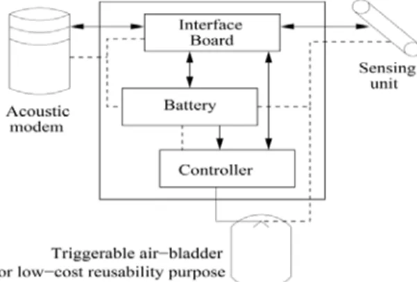
Fig 1: A low-cost underwater sensor node with sensing, Acoustic communication and re-usability capabilities
On the other hand, UWSN only incurs a fraction of implementation cost of UANET at the same network scale. All sensor nodes in a UWSN are of low-cost (without self-propelling power). Fig 1 shows a node configuration. A large number of such non-powered low-cost sensor nodes can be thrown into the ocean to float at various depths for short-term monitoring, and can also be mounted on the seabed or chained to a number of buoys for long-term monitoring.
B. Underwater acoustic (UW-A) channel assumption
The communication characteristics of the Underwater Acoustic (UW-A) channel are with following innate characteristics. Narrow and low bandwidth, the available bandwidth of the UW-A channel is limited and strongly depends on both range and frequency. UW-A channel’s acoustic band is limited due to absorption with most acoustic systems operating below 30 kHz. This fact has two significant impacts on underwater communication. First, the entire width of underwater acoustic frequency band is very narrow; so far the highest value reported is around 1MHz at the range of 60m radius.
only several tens of bits per second, while a short-range system operating over several tens of meters may have several tens of kilobits per second. Compared to radio or wired links, in both cases bit rates are significantly lower. Very large propagation latency is encountered.
The signal propagation speed in the UW-A channel is only 1.5×10³m/sec, which are five orders of magnitude lower than radio propagation speed 3×10⁸m/sec in the air. Compared to acoustic propagation delay, electromagnetic propagation delay is negligible.
C. Challenges in communication and signal processing
In this section design challenges are identified along the network protocol stack in a top-down manner. At each layer there are critical problems awaiting solutions.
D. Distributed GPS-free localization and time synchronization services
In underwater applications, it is critical to let every underwater node know its current position and the synchronized time with respect to other coordinating nodes. Nevertheless, the high-frequency radio wave used by Global Positioning System (GPS) is quickly absorbed by water, hence cannot propagate deeply under the water surface. So far from the information, a scalable and low-cost positioning and time-synchronization system like GPS is not yet available to underwater nodes.
This is significantly different from ground-based MANET and WSN where GPS services are typically available, for example, directly from GPS interfaces in outdoor cases and at most 2 or 3 hops away in indoor cases. The key problem in a network with node mobility is the range and direction measurement process itself. The common GPS-free approach used in many ground sensor networks of measuring the Time-Difference-of-Arrival (TDoA) between an RF and an acoustic/ultrasound signal (e.g., the AhLoS project and the Cricket project) is no longer feasible as the commonly available RF signal fails under water.
C. Acoustic link layer and physical layer
Underwater acoustic communications are mainly affected by path loss, noise, multi-path, Doppler spread, and large and variable propagation delay. All these factors determine the temporal and spatial variability of the acoustic channel, and limit the data rate of communication over the Under-Water Acoustic channel. The path loss depends on both transmitter-receiver (TR) separation distance and the acoustic frequency, which is different from that for microwave channels[5]. Long-range systems that operate over several tens of kilometers may have a bandwidth of only a few kHz (since high frequencies experience high attenuation over long distance), while a short-range system operating over several tens of meters may have more than a hundred kHz of bandwidth. In both cases these factors lead to low bit rate, in the order of tens of kbits/s for existing devices.
The multi-path effect of the acoustic channel can be mitigated by equalization or orthogonal frequency division multiplexing (OFDM). The Doppler Effect due to motion of the transmitter and/or the receiver can be utilized in the design of channel codes and interleavers. For example, suppose the Doppler rate is fD; then the
coherence time Tc is roughly 1/fD. Then the length of the interleaver or the codeword length should be at least
2 × TC = 2/fD.
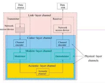
To support QoS, recently developed effective capacity technique may be utilized. Fig 2 shows a wireless communication system. The data source generates packets and the packets are first put into a buffer to accommodate the mismatch between the source rate and the time-varying acoustic channel capacity. Then the packets traverse a channel encoder, a modulator, a wireless channel, a demodulator, a channel decoder, a network access device, and finally reach the data sink. As shown in Fig 2, one can model the communication channel at different layers, e.g., physical layer and link layer.
Fig 2: Wireless communication system
Small-scale fading models describe the characteristics of generic radio paths in a statistical fashion. Small-scale fading refers to the dramatic changes in signal amplitude and phase that can be experienced as a result of small changes (as small as a half-wavelength) in the spatial separation between the receiver and the transmitter. Small-scale fading can be slow or fast, depending on the Doppler rate. Small-Small-scale fading can also be flat or frequency-selective, depending on the delay spread of the channel.
Uncorrelated scattering is often assumed, to extend these distributions to the frequency-selective case. The large-scale path loss and small-scale fading together characterize the received signal power over a wide range of distances. A modem-layer channel can be modeled by a finite-state Markov chain, whose states are characterized by different bit error rates (BER). A codec-layer channel can also be modeled by a finite-state Markov chain, whose states can be characterized by different data-rates, or symbol being error-free/in-error, or channel being good/bad. The two state Markov chain model with good/bad state is widely used in analyzing the performance of upper layer protocols such as TCP.
Acoustic-layer channel models provide a quick estimate of the performance of acoustic communications systems (e.g., symbol error rate vs. signal-to-noise ratio (SNR)). However, acoustic-layer channel models cannot be easily translated into complex QoS guarantees for a connection, such as bounds on delay violation probability and packet loss ratio.
The reason is that, these complex QoS requirements need an analysis of the queueing behavior of the connection, which is hard to extract from acoustic-layer models. Thus it is hard to use acoustic-layer models in QoS support mechanisms. Recognizing that the limitation of the physical-layer channel models in QoS support is the difficulty in analyzing queues, we proposed moving the channel model up the protocol stack, from the physical-layer to the link layer. An effective capacity channel model was proposed. Effective capacity captures the effect of channel fading (including Doppler Effect) on the queueing behavior of the link, using a computationally simple yet accurate model, and thus, is the critical device we need to design an efficient resource allocation mechanism.
III. SEA SWARM APPLICATION SCENARIO
A SEA Swarm (Sensor Equipped Aquatic Swarm) is deployed in a square region of size L m × L m whose depth ranges from D1 to D2 (D = D2D1). Once nodes are deployed, they adjust their depths using bladders and on-board pressure gauges to assure even sensor distribution in the 3D region. The swarm moves along water current, searching for a stranded submarine or scouting the waters around a friendly convoy to detect underwater intruders. There are a few AUVs (e.g., unmanned submarines) in the swarm that assist in further investigation of the alert situation [2]. For instance, they can help the rescue of stranded vessels, and they may also carry weapons to destroy attackers.
unmanned submarines. The selection of a submarine depends on the nature of the detected event. There is at least one corresponding submarine for each type of an event. For instance, if a sensor detects a type A event, it sends the event to submarine A; type B to submarine B, and so on. Assume that the submarines patrol constantly the swarm area using random direction mobility. An ad hoc routing protocol is necessary in order for the moving sink to receive the data from mobile sensors. Proactive routing protocols such as OLSR requires period updates and reactive routing protocols such as AODV requires flooding for route discovery. Directed Diffusion a popular technique in sensor networks to establish routes to sinks, also involves flooding for route discovery and requires route maintenance especially in mobile environments [6].
To avoid the overhead of these approaches, it is proposed to use beaconless geographic routing in 3D environments [3]. Once the location of the destination node (i.e., the sink node) is known, a mobile sensor can exchange location updates while communicating with a mobile sink. Geographic routing requires a geographic location service, and this paper aims at designing an efficient and scalable location service for a SEA Swarm. In the following, we describe the protocol details and show our design choice.
Note that nodes can localize their positions using existing localization techniques. In particular, nodes can “passively” learn their positions from other nodes (e.g., AUVs) to minimize energy consumption such as Dive’N’Rise (DNR), mobility prediction or using autonomous underwater vehicle.
A. Protocol design space analysis
The performance of existing location service protocols in the SEA Swarm scenario. Assume that N mobile nodes are deployed in a L m × L m × D m cubic space, and the mobile node has a communication range of R. For the sake of analysis D = L, but in practice, the width of a monitoring region size is much greater than the depth. Let M denote the number of hops to travel the horizontal width of the swarm; i.e., M = L/R, where R means the acoustic transmission range. Consider the following location service protocols, namely native flooding, quorum based schemes, and hierarchical schemes [7]. The operations of a location service are location update and retrieval (query).
• Native flooding: A node periodically floods its current position to the entire network.
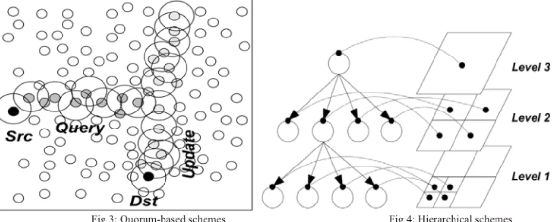
• Quorum-based schemes: Each location update of a node is sent to a subset of nodes (or update quorum), and similarly, a location query is sent to a subset of nodes (or query quorum). The query will be resolved only when these two subsets are designed such that their intersection is non-empty. For instance, in XYLS, each node propagates its location update in the vertical direction, whereas any location queries are disseminated in the horizontal direction. (Fig 3)
Fig 3: Quorum-based schemes Fig 4: Hierarchical schemes
• Hierarchical schemes: Location servers are chosen via a geographic hash function. The entire area is recursively divided into a hierarchy of smaller grids, thus building a hierarchical tree. The root of a tree covers the whole network area, and each of its siblings covers a smaller grid whose size is one fourth of the network area (see Figure 4).
communication range. Level i grid has the size of
2i1R ×2i1R
. Let H denote the maximum level of the hierarchy, satisfying the relationship ofL = 2H1.
B. Location Services
Location services can be divided into two categories in general, namely flooding-based, and rendezvous-based approaches. Intermediate approaches can also be constructed. As in ad hoc routing protocols, flooding based protocols are either proactive or reactive. For instance, DREAM is a proactive algorithm; LAR is a reactive algorithm. In rendezvous-based protocols, all nodes agree upon a certain mapping that maps one’s ID to a set of nodes (or location servers, rendezvous nodes) in the network.
In XYLS, a node stores location updates in a vertical line and retrieves the location by sending a query in a horizontal direction. Proposed double ruling methods where they store information on a 1D curve (circle) in a sensor network. The consumer travels along another curve which guarantees to intersect with the producer curve. It is an extension of the hashing scheme of GHTs with improved query locality, i.e., consumers close to producers.
Trail Protocol uses a similar concept, but a location update is locally stored instead of always propagating on a curve. In hashing-based protocols, location servers are chosen via a hash function in the node’s identifier space. Hashing schemes can be further divided into flat or hierarchical schemes. In a flat scheme such as GHT, location information is stored in a single geographic location. In a hierarchical hashing-based scheme such as GLS, HIGH-GRADE and MLS, the area in which nodes reside is recursively divided into a hierarchy of smaller grids.
A node publishes its current location to those who encounter a target node. Encounter history is disseminated via node mobility. For location discovery, a node searches for any intermediate node that encountered the target node more recently through expanding disk search. Having found such an intermediate node, EASE (Exponential Age Search) estimates target’s location as the position where the intermediate node encountered the target, and FRESH (Fresher Encounter Search) does it as the current position of the intermediate node. Since a query packet can travel much faster than swarming sensor nodes, by repeating this process, one can quickly find the target’s location. This can be seen as “approximate” level-of-indirection to the exact location as in hierarchical schemes. These approaches assume mobility models where encounter history well diffuses around the network.
Moreover, BC neither handles the node mobility nor provides a search mechanism. Trail Protocol takes advantage of high speed mobility of AUVs, explicitly maintains a pheromone trail whose length is controllable, and provides an efficient spiral curve search algorithm to retrieve location information.
C. Bio-inspired Networking Systems
Understanding key ideas of how living organisms efficiently organize unreliable and dynamically changing resources and applying these ideas to distribute computing has been an active area of research for the past decade. Conceptual framework captures a few basic biological processes such as diffusion, chemo taxis, and stigmergic. For ad hoc routing, a few proposals have already emerged, such as ARA, PERA, and AntHocNet. ARA and PERA are quite similar to a reactive ad hoc routing protocol, e.g., AODV. On the contrary, AntHocNet is a hybrid (both proactive and reactive) multi-path ad hoc routing protocol and consists of two main processes: stigmergic learning and diffusion. During stigmergic learning, nodes send out ant-like agents (similar to RREQ control packets in AODV) which sample and reinforce good paths to the destination.
IV. TRAIL PROTOCOL LOCATION SERVICE
In this section, the protocol design assumptions is described, presents the details of the proposed location service protocol, and analyses the cost of protocol operations.
A. Trail Protocol Operations
proposed to use a 2D upper hull of the SEA Swarm topology for practical reasons. Fixing an arbitrary depth as a reference does not guarantee that there will be sensors at that depth all the time, failing to assure a reasonable concentration at the reference depth. Instead, a set of nodes is taken on the upper hull within a threshold depth (say, communication range) to assure connectivity in view of the previous assumption. Note that the performance loss due to routing packets to the upper hull is minimal, because a typical swarm has a vertical dimension smaller than other dimensions.
Upper Hull Maintenance: In Trail Protocol, mobile nodes on the surface of deployment become location servers. Since a swarm is deployed in a square region of size L × L whose depth ranges from D1 to D2, we use nodes located in between D1 and DH as location servers where we have DH < D2. Sensors can accurately estimate their depth via on board pressure gauges (avg. error < 1m ). Once acquired this information, mobile sensors check whether they are within this depth range and automatically set their node status.
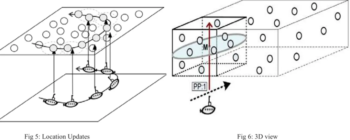
Fig 5: Location Updates Fig 6: 3D view
Location Update: The key idea of Trail Protocol is to store the location updates along the projected trajectory of an AUV on the upper hull as shown in Figure 5. While moving, the AUVs leave pheromones on mobile sensor nodes in the upper hull by sending a pheromone packet that has a unique sequence number and the current position and direction of the submarine. The packet is routed in two steps:
(1) Vertical routing to the upper hull (any cast),
(2) 2D geographic routing to the cylinder area (geocasting).
In the first phase, the packet is routed vertically until it reaches a node on the hull. The depth information is only used to make a forwarding decision: a packet is forwarded to a node whose depth is smallest among all neighbours (i.e., greedy forwarding). Once it hits the upper hull, one has to switch to the second phase where 2D geographic routing is performed to route the packet to the projected x and y coordinate.
A node that is closest to the projected point on the upper hull stores the pheromone packet. For robustness, it can relax this constraint such that any nodes surrounding the projected point store the packet as shown in Fig 6. Since the upper hull has the depth of DH D1, the surrounding area becomes a cylinder: any nodes in the cylinder store pheromone packet. If a single transmission cannot cover all the nodes within the cylinder, the packet needs to be re-broadcast (along the vertical direction). Note that a possible alternative to this two-phase approach is to pick an arbitrary projected point in the upper hull (say, the mid-point M in the figure) and route the packet using 3D geographic routing. When a packet is vertically routed, due to voids, it may reach a local maximum node whose depth is lowest among all its neighbours (so it cannot make any progress), and whose location is not within the communication range of the projected point.
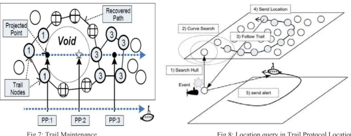
Fig 7: Trail Maintenance Fig 8: Location query in Trail Protocol Location Service
This process is particularly useful for handling voids on the hull. As mentioned earlier, voids make a trail disconnected since pheromone packets cannot be stored in the void areas. Nonetheless, after passing a void area, there will be a new pheromone packet that can be stored in the upper hull (and whose sequence number is greater than the one before). If that happens, one of nodes starts a trail recovery process: i.e., a hop-limited recovery packet is flooded, and detour paths along the void area are created as illustrated in Figure 7. Note that in the simulations, the Meandering Current Mobility (MCM) Model is used, that describes mobility patterns of floating objects by the Gulf Stream for a given depth (2D mobility patterns).
Location Query: A mobile node first routes a query packet vertically upwards to the node on the projected position of the upper hull. After this, the node performs an expanding Spiral curve search. It starts with a single hop (k = 1), just like expanding ring search (2D disk). If it fails to find the trail, the hop limit is exponentially expanded: i.e., for step k, the hop limit is given as h = 2k. If k > 1, the search packet travels along a circle with radius h hops. This can be easily detected by checking the sequence numbers and timestamps. Note that a simple alternative of this spiral curve search is a random-walk based search: a query packet performs a random walk until it hits a pheromone rail. The asymptotic search cost is equivalent in both cases. The various phases of the Trail Protocol search are illustrated in Fig 8.
V. SIMULATIONS
In this section, the performance of Trail Protocol is evaluated using Microsoft Visual Studio 2008 and compared its performance with other protocols, namely XYLS and HIGH-GRADE. A custom acoustic communication module is used as the physical layer. Communication range is set to 50m. The ALOHA MAC protocol is used as the main concern is not throughput/reliability. Simulation time was 3000 seconds. Therefore two mobile sinks moved at the speed of 10 m/s and send an update for every 5 seconds.
This repeats until it reaches a node on the hull. Nodes move according to the Meandering Current Mobility (MCM) Model that describes mobility patterns of floating objects by the Gulf Stream for a given depth (2D mobility patterns). MCM has two important components, the main jet (0.3m/s) and vortexes around it. Note that nodes may move beyond the simulated area due to mobility. In the simulations, nodes are initially deployed in the 3D area of size 200m × 200m × 150m. The initial x and y coordinates are randomly chosen from 0 to 200. MCM is evaluated to 3D environments by generating 2D patterns at three strata, namely z = 50, 100 and 150m.
In the simulations, we measure:
(1) The overhead of each operation by the total number of transmitted messages associated.
(2) The query success ratio that is the ratio of total number of succeeded queries to the total number of queries.
Update overhead: Figure 9 shows the average location update cost as a function of the number of nodes. Location update cost is the average number of update packets forwarded per update (i.e., on average, how many times an update packet has to be forwarded in order to finish the update procedure). In Trail Protocol, for instance, a packet is first vertically routed and stored in a node on the hull. The figure shows that Phero- Trail has lower number of packet exchanges than XYLS and HIGH-GRADE. XYLS has higher update costs than Phero- Trail because it has to disseminate an update in a line on the hull (north-south direction). HIGH-GRADE incurs a similar overhead as Trail Protocol due to its localized location update. Query overhead: Figure 9 shows the average location query cost as a function of the number of nodes. The location query cost is the average number of query packets forwarded per query (i.e., on average, how many times a query packet has to be forwarded in order to answer the query).
Query success rate: Figure 10 shows the query success rate. HIGH-GRADE performs poorly as opposed to Trail Protocol and XYLS. Unlike HIGH-GRADE, both Trail Protocol and XYLS maintain explicit line structure for location look-up and thus, it is robust to mobility and non-uniform node distribution (due to node mobility). As HIGH-GRADE uses uniform hashing to map node’s ID to geographic location, it is possible that there are no neighbouring nodes in the mapped location. We also performed a sensitivity analysis of Trail Protocol. To this end, two different scenarios are considered, by varying
(1) The number of submarines from 2 to 5 (and update interval accordingly), and (2) The network size
Figure 10 shows the success rate with the 5 submarines. Since the protocol parameters (e.g., update interval) is properly adjusted based on the sink speed, compared to the success rate of a 2 submarine, are does not observe any notable difference. Figure 10 shows the success rate when 100 sensors are initially deployed in an area. The success rate is slightly reduced because more number of sensors is deployed in a larger area, but the overall trend is still consistent.
VI. CONCLUSION
A geographic location service has been enabled in geographic routing in a SEA Swarm. So maintaining location information in a 2D plane is a better choice in the environment under consideration. Given this, a novel bio-inspired location service called a Trail Protocol location service protocol where a trajectory of a mobile sink is projected to the nodes in the 2D upper hull for location update and retrieval. Under reasonable assumptions, it is shown that the performance of Trail Protocol is comparable with the hierarchical schemes, in terms of location query and update. However, when the reference point update overhead is accounted, Trail Protocol is superior. There are several interesting avenues for future work on this subject.
Finally, one can improve the issues of balancing loads and energy consumption, because the upper hull is more heavily utilized than other layers. The problem can be mitigated by gracefully switching the depth of the 2D plane over time.
REFERENCES
[1] J. Kong, J.-H. Cui, D. Wu, and M. Gerla. Building Underwater Adhoc Networks and Sensor Networks for Large Scale Real-time Aquatic Applications. In IEEE MILCOM’05, Atlantic City, NJ, Oct. 2005.
[2] M. Erol, L. F. M. Vieira, and M. Gerla. AUV-Aided Localization for Underwater Sensor Networks. In WASA’07, Chicago, IL, Aug. 2007.
[3] R. Flury and R. Wattenhofer. Randomized 3D Geographic Routing. In INFOCOM’08, Phoenix, AZ, Apr. 2008.
[4] R. Friedman and G. Kliot. Location Services in Wireless Ad Hoc and Hybrid Networks: A Survey. Technical Report CS-2006-10, Technion- Israel Institute of Technology, Apr. 2006.
[5] C. Intanagonwiwat, R. Govindan, and D. Estrin. Directed Diffusion: a Scalable and Robust Communication Paradigm for Sensor Networks. In ACM MOBICOM’00, Boston, MA, USA, 2000.
[6] L. Badia, M. Mastrogiovanni, C. Petrioli, S. Stefanakos, and M. Zorzi. An Optimization Framework for Joint Sensor Deployment, Link Scheduling and Routing in Underwater Sensor Networks. In WUWNet’06, Los Angeles, CA, Sep. 2006.
[7] Aydin and C. Shen. Facilitating Match-Making Service in Ad hoc and Sensor Networks Using Pseudo Quorum. In ICCCN, Oct. 2002. [8] S. Basagni, I. Chlamtac, V. R. Syrotiuk, and B. A. Woodward. A Distance Routing Effect Algorithm for Mobility (DREAM). In