Multiple Impinging Jet Air-Assisted Atomization
Bruno Pizziol
1, Mário Costa*
1, Miguel Oliveira Panão
2, André Silva
31
IDMEC-LAETA, Instituto Superior Técnico, Universidade de Lisboa, Lisboa, Portugal
2ADAI-LAETA, Universidade de Coimbra, Coimbra, Portugal
3
AreoG-LAETA, Universidade da Beira Interior, Covilhã, Portugal
*Corresponding author: [email protected]
Abstract
The growth of the aviation sector triggered the search for alternative fuels and continued improvements in the combustion process. This work addresses the technological challenges associated with spray systems and the concern of mixing biofuels with fossil fuels to produce alternative and more ecological fuels for aviation. This work proposes a new injector design based on sprays produced from the simultaneous impact of multiple jets, using an additional jet of air to assist the atomization process. The results evidence the ability to control the average drop size through the air-mass flow rate. Depending on the air-mass flow rate there is a transition between atomization by hydrodynamic breakup of the liquid sheet formed on the impact point, to an aerodynamic breakup mechanism, as found in the atomization of inclined jets under cross-flow conditions. The aerodynamic shear breakup deteriorates the atomization performance, but within the same order of magnitude. Finally, our experiments show that mixing a biofuel with a fossil fuel does not significantly alter the spray characteristics, regarded as a step further in developing alternative and more ecological fuels for aero-engines.
Keywords
Impinging Jets Atomization, Air-Assisted, Biofuel Introduction
In the commercial aviation sector, aircraft fleets operate on single fossil fuel products, and contribute to 3% of global carbon emissions [1]. Increasing concerns around the environmental impact of the sector, along with its future growth rate – estimated to be 4.7% every year on fleet basis [2] – raised the interest in improving the efficiency of engine combustion technology to reduce greenhouse gases emissions. One of the most prominent strategies is the use of biofuels based on renewable feedstock toward a more neutral carbon cycle. However, one of the key components in aero-engines is the fuel atomization, and introducing biofuels or mixtures between fossil jet fuels and biofuels requires making sure the differences in thermo-physical properties do not alter spray formation and development, and droplets characteristics.
Alternative fuels allow a faster benefit, since industrial assets of the aeronautical sector do not restrict their development, where high investment costs slow innovation in their production [3]. Using alternative fuels presents further advantages over the use of fossil jet fuel, as a reduced cost fluctuation, a worldwide homogeneous distribution of the feedstock and, depending on the alternative fuel production, better fuel properties [4]. In light of this, the use of alternative jet fuels expects a growth of 30% until 2030 [5].
Among engine components, the atomizer affects in a great extent the combustion promptness, cleanness, and efficiency. The technological development of this component aims at achieving the best atomization – in terms of evaporation rate and spray penetration – while reducing power consumption for the pressurization of the fuel and, if present, the atomizing fluid.
In this context, this work explores the use of an atomization strategy based on the simultaneous impact of multiple impinging jets (2, 3 and 4) to design a spray system with the ability to have some control over the atomization process. While the use of multiple impinging-jets lowers the liquid supply pressure and produces relatively small droplets (depending on the jet diameter), the assistance of an air-jet is the hypothesis for a more adequate control of the atomization process. To the best of our knowledge, Avulapati and Venkata [6] proposed this strategy for a wide range of experimental conditions, although restricted to the impingement of 2 jets. Besides the injector design, through an analysis of the spray characteristics, we assess the effect of mixing biofuel to a fossil fuel by analysing the atomization efficiency.
Materials and Methods
To investigate the effect of the air assisting the atomization process in a multiple jets impingement strategy, the injector prototype developed can collide up to 12 cylindrical jets. Fig. 1 shows a schematic of the injector design for the case of 2-impinging jets. The injector composes an upper part, referred to as injector tail (A), and a lower part, referred to as injector head (B). The two parts connect on a horizontal surface, referred to as connection surface, through bolted joints.
Figure 1. Schematic of the injector and details of the impinging jets configuration.
The injector tail is the vertical segment through which the fuel and the air flow from the connections to the corresponding feed lines (C and D) connected with the injector head, which holds the atomizer. The fuel and the air nozzles (E and F) are separate components, screwed to the injector head. Interchangeable nozzles allow using the same injector head for the experimental characterization of different atomizer configurations, in terms of nozzle diameter and length, and number.
The fuel path through the injector has three distinct stages. A first stage through the vertical feed line to the bottom of the injector tail, a second stage, where the fuel follows a horizontal path, and a third stage of angled flowing towards the impingement point G.
The injector tail comprises two concentric tubes, defining the axial channels of both air (within the internal tube) and fuel flow (between the internal and external tubes). Its length is 500 mm for a symmetrical flow development and to compensate any misalignment on the feed-line connection.
In the second stage, the fuel path develops from the inner to the external region of the injector head. As the flow reaches the end of the axial channel, it branches into two radial channels (one for each nozzle block) carved into the injector head connection surface. As for the axial channel, the width of 2 mm guarantees a correct development of the flow within the section. The fuel leakage through the connection plane, directed towards both the external atmosphere and the internal air path, is avoided using an internal and an external large O-rings. In the third and final stage, the flow moves from the external end of the radial channel to the impingement point with a fixed impingement angle of 45°. The diameter of the fuel inner tube is 0.5 mm, resulting in a laminar flow for all conditions (Re < 2300). In the laminar regime, the entrance length to ensure a fully developed flow at nozzle exit (xfd) is 0.05Re ∙ . For the highest flow rate, this corresponds to a length of 40 mm, and the tube has 46 mm, thus, every fuel mass flow rate considered is fully developed at nozzle exit. Also in this case, an O-ring between the nozzle screw head and the injector head avoids fuel leakage through the nozzle thread.
The air flow exits from a vertical 10 mm tube coaxial with the fuel feed line, through the injector tail until the 1 mm diameter nozzle. The air flow impingement distance is 10 mm. Fig. 2 shows the injector and the spray produced by the multiple impinging jets atomizer.
Figure 2. Injector and spray produced by the multiple impinging jets atomizer (left); Spray produced by the 2-4 impinging jets
configurations considered without the central air flow rate [ 1.67 g/s – Jet Fuel; 1.54 g/s – Fuel Mixture] (right). The experiments used two fuels. A commercial Jet Fuel A-1 used in aero-engines and an alternative fuel 50:50 blending the previous Jet Fuel with a Biodiesel known as NEXBTL (Next Generation Biomass-to-Liquid) produced by Neste Oil. Table 1 presents the relevant physical properties for atomization of the two fuels.
Table 1. Physical properties of the fuels. Density at 15 ºC [kg/m3] Surface tension at 20 ºC [N/m] Dynamic viscosity at 20 ºC [Ns/m2]
Commercial Jet Fuel A-1 785.8 0.0225 0.0044
‘Jet Fuel’ – ‘Biodiesel NEXBTL’ (50:50) 782.0 0.0225 0.0038
Experimental Setup and Diagnostic Techniques
During the experiments, the injector was in the vertical position, with the injector head – air and fuel nozzles – on the bottom and the connections to the air and fuel feed-lines on the top. An air feed-line connects to the injector top from the pressurized line at 7.5 bar. A pressure regulator reduces this value to 2.5 bar before entering the rotameter. In these conditions, the line provided a mass flow rate through the air orifice up to 0.6 g/s.
The fuel feed-line connected the pressure vessel to the injector top, loading it in the vessel at atmospheric pressure. A high-pressure bottle of gaseous nitrogen pressurized this vessel, but a pressure regulator set between the two, reduced the 200 bar pressure in the bottle to the injection value of 3.2 bar. A rotameter between the vessel and the end of the feed-line controlled the fuel flow. An additional ball valve allowed for prompt closure, reducing the fuel consumption. This pressure reduction to injection values, coupled with injector head configuration, presented the higher losses, and allowed using the rotameter full scale when setting the fuel mass flow rate. Thus, the maximum value available in these conditions is 5.90 g/s.
A laser diffraction diagnostic technique (Malvern 2600 Particle Size Analyser) was used to measure the droplet size distributions for the various sprays examined as a function of the injector head configuration and position, fuel and air flows. The instrument comprised a low power 5 mW He-Ne laser transmitter and a receiver detector unit. The collimated 9 mm diameter beam, produced by the transmitter associated optics, was directed into the spray perpendicularly to its axis. The receiver lens used was a 300 mm focal length lens, which is able to measure droplets ranging from 5.8 to 564 m. In this study, we restricted the droplet size measurements to spray regions where the obscuration, which is a measure of the attenuation of the laser intensity through the spray, was less than 0.5, so that multiple scattering effects were negligible. Finally, to fit the measured energy distribution we used the model independent (a fifteen parameter function), available in the Malvern software, which provided excellent fits of the experimental data – log errors of around 3.
In addition, a Phantom V4.2 HSC (High Speed Camera) was used to visualize the atomization mechanisms near the impingement point (see Fig. 2). An exposure time of 1 μs allowed capturing the ligaments formation and the main structures in the spray pattern.
Results and Discussion
From the results characterizing drop sizes in air-assisted multijet impinging sprays with Nj = 2, 3 and 4 impinging jets, we analyse the effect of the air-mass flow rate on the Sauter mean diameter retrieved from the distribution measured by the laser diffraction diagnostic technique. Subsequently, we develop a definition for the efficiency of atomization and analyse the results.
Effect of Air-Mass Flow Rate on Average Drop Sizes
A preliminary analysis of the spray characterization evidenced the air-mass flow rate as the main parameter changing the atomization outcome. Figs. 3 and 4 show the effect of that parameter on the Sauter mean diameter.
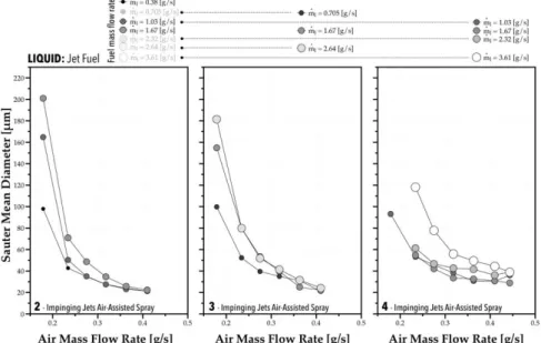
Figure 3. Effect of the air-mass flow rate on the SMD of the Jet Fuel for different impinging-jets configurations (2, 3 and 4 jets) and mass flow rates ( 0.38 – 3.61 g/s).
Note that the size of the symbols in Figs. 3 and 4 is proportional to the fuel mass flow rate. While increasing the mass flow rate leads to larger average drop sizes in every configuration, as reported by several other authors, our results point to the fundamental role of the air flow rate in dominating the atomization process, more than the air/fuel ratio. A closer visualization of the impact point region explains why. Fig. 5 shows the effect of the minimum and maximum air-mass flow rate in the deflection of the impinging jet for the case with 3-jets, and the change in the atomization mechanism from hydrodynamic forces to aerodynamic, with a small increase of air-mass flow rate. The figure reveals that there is a threshold above which increasing the air-mass flow rate leads to a deflection of the impinging jets and, instead of producing droplets by hydrodynamic breakup from the liquid sheet formed at the impact point, the aerodynamic forces dominate breakup, like the atomization of inclined jets under cross-flow [7, 8]. The two images on the right of Fig. 5 show the differences in the spray structure with an increase of 15% in the air-mass flow rate ( 0.18 – 0.41 g/s).
The disruptive effect of the aerodynamic forces intensifies the atomization mechanisms, resulting in smaller drop sizes. Only with the 4-impinging jets does the mass flow rate produce some effect on the average drop size. However, it is noteworthy that the order of magnitude of the average drop sizes is similar for all configurations, which points to the possibility of controlling drop size through the atomizing air flow.
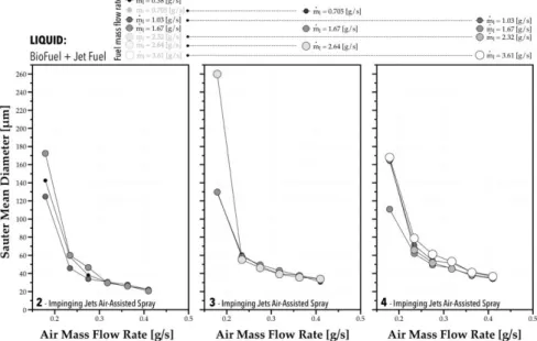
With the 50:50 mixture of Jet Fuel and NEXBTL Biodiesel, the dominating effect of the air-mass flow rate remains. However, while in the conventional jet fuel spray, the mass flow rate induced a slight variability in the results, with the fuel mixture, such effect is negligible. These results suggest that mixing biodiesel with fossil jet fuel does not alter the average size of droplets in the spray.
Figure 4. Effect of the air-mass flow rate on the SMD of the Jet Fuel-Biodiesel Mixture for different impinging-jets configurations (2, 3 and 4 jets) and mass flow rates (m 0.38 – 3.61 g/s).
Figure 5. Effect of the minimum and maximum air-mass flow rate in the deflection of the impinging jet for the case with 3-jets (2 images on the left); Change in the atomization mechanism from hydrodynamic forces to aerodynamic, with a small increase
of air-mass flow rate (2 images on the right).
In light of this, we suggest an empirical approach to examine the effect of the air-mass flow rate (m / ) on the Sauter Mean Diameter ( ). expressed as
, ∙ (1)
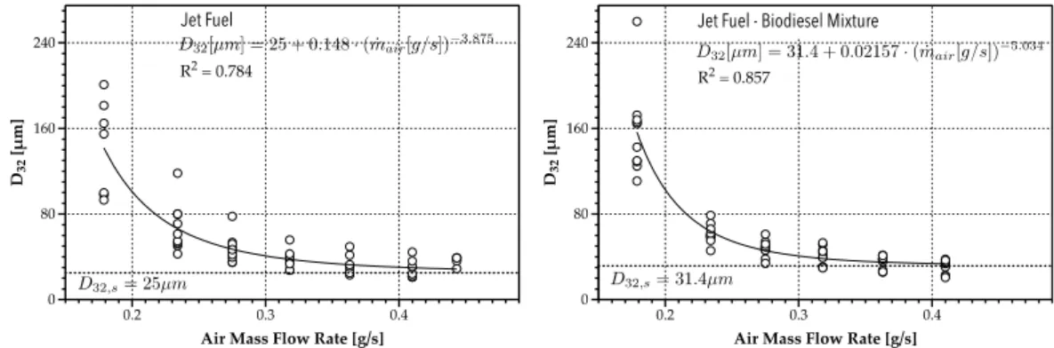
This expression considers a stabilization of as the air-mass flow rate ( ) increases, represented by , . The empirical coefficient a represents a scale parameter associated with the air flow effect, and b its magnitude on the outcome. Fig. 6 shows the results of the curve fitting in Eq. (1) for the experiments with Jet Fuel (left) and biofuel mixed with Jet Fuel (right).
The empirical correlations in Fig. 6 point to the marginal effect of mixing biodiesel to fossil Jet Fuel in terms of the average size of droplets. Therefore, the mixing does not appear to generate droplets with different characteristics in the experiments reported. However, the increase of exponent b in the correlation with the Jet Fuel-Biodiesel 50:50 mixture suggests an improvement of the air-mass flow rate ability for controlling average drop size. This points to a robust atomization strategy based on air-assisted multiple impinging jets, although requiring an analysis from the point of view of the atomization efficiency, performed below.
The correlations in Fig. 6 are still dimensional. Thus, if we normalize by the lower limit to the average drop size ( ,), resulting from the effect of the air-mass flow rate,
∗ ,
Figure 5. Empirical correlation between the air-mass flow rate on the SMD of the conventional Jet-Fuel and the 50/50 mixture between Jet Fuel and NEXBTL Biodiesel Mixture.
and, instead of the air-mass flow rate, consider the relation between a scale for the volumetric kinetic energy of the air jet,
, ~
1
where / is the air density, the diameter of the air jet at nozzle exit, relatively to a scale for the volumetric surface energy of the lower limit for the average drop size
, ~
,
we relate both to scale the non-dimensional effect of the air jet as , ′′′ , ′′′ 1 2 2 32,
The result for both fuels provides the following empirical correlation
∗ 1 79.28 ∙ . (2)
where Θ , , 10 . The correlation depicted in Fig. 7 obtained for our results shows a reasonable agreement (see Fig. 8 which includes the standard deviation of the residual value between experimental data and the results obtained from the correlation), including its application with data reported in the literature by Avulapati and Venkata [6].
Figure 6. Normalized correlation a normalized D32 and a
scale parameter relating the volumetric kinetic energy of the jet with the volumetric surface energy of the lower limit
for D32. The results plotted include all experimental
conditions and both fuels.
Figure 7. Comparison between experimental results and those provided by the correlation in Eq. (2), including the
data from ref. [6] within the validation domain.
A possible explanation for the stabilization of might be related to the change of the breakup mechanisms. When aerodynamic forces dominate breakup, a liquid sheet forms at the end of the deflected jet before reaching the impact point, detaching in ligaments by shear breakup further downstream. The scale of shear breakup involves the wavelength of the liquid surface waves, which is of the order of λs/dj ≈ 0.1 [9]. Therefore, considering
the size of our impinging jets, this results in λs ≈ 50 μm, which is similar to the Sauter mean diameter measured for the highest air-mass flow rate.
Atomization Efficiency
The definition of the atomization efficiency is not straightforward. Avulapati and Venkata [6] define it for air-assisted multiple impinging jets atomization as
a. the difference between the sum of surface energy of all droplets and the jets’ initial surface energy; b. divided by the sum of gas and liquid energy.
The energy in the air jet corresponds to the isothermal compression required to compress the atomizing air. However, this assumption is based on effervescent sprays where the air dissolved in the liquid compose the two-phase mixture injected. We argue instead that air-assisting multiple impinging jets relates the final volumetric surface energy of droplets produced by atomization,
, 6
6
with the total energy available from the kinetic component of the air jet ( ), plus the kinetic and surface components available on the liquid jets ( ),
, (3)
Therefore, while in effervescent sprays the air assists atomization from inside out, in our case and the case of Avalupati and Venkata [6], the assistance is the opposite. Fig. 9 depicts the results obtained for the atomization efficiency in the present experiments.
Figure 8. Effect of air-mass flow rate on the spray atomization efficiency for all configurations and operating conditions ( 0.38 – 3.61 g/s).
The present efficiency values are larger than those reported by other authors. This could be the result of the definition of the atomization efficiency. Although a higher air-mass flow rate produces smaller droplets due to a change in the atomization mechanism (from hydrodynamic to aerodynamic), this occurs as the cost of performance, since, obtaining droplets of smaller sizes means a lower atomization efficiency because is takes more energy to breakup the liquid into smaller droplets. It is noticeable that the atomization efficiency is more sensitive to the mass flow rate in the case of 4-jets relatively to the remaining configurations. However, when biodiesel is mixed with Jet Fuel, we observe some changes. Namely, (i) the atomization efficiency ceases being affected by the mass flow rate, which is more evident with the 4-jets spray; (ii) the effect of the gas mass flow rate on atomization efficiency is more systematic; and (iii) maximum atomization efficiency obtained between 0.2 0.25 / in every configuration.
Concluding Remarks
The continued growth rate of the aviation sector demands the search of alternative and more ecological fuels. However, this implies optimizing the combustion process for the new fuels and improved spray systems as key
components. The purpose of this work is twofold. First, we propose a new injector design based on air-assisting multiple impinging jets sprays. Second, we address the concern that mixing biofuel to a fossil fuel, as a first approach to produce alternative fuels, might alter sprays characteristics and the combustion process. The results point to the following conclusions:
in multiple impinging jets sprays, considering 2, 3 and 4 jets, the air flow rate assisting atomization allows some control over the average drop size;
a transition occurs between hydrodynamic and aerodynamic atomization breakup mechanisms when the air-mass flow rate increases;
this transition deteriorates the efficiency of the atomization process, but within the same order of magnitude the range of air flow rates considered;
mixing biofuel with fossil jet fuel does not significantly alter spray characteristics, thus, this alternative should not produce changes in droplets characteristics that would negatively influence the combustion process. Acknowledgements
This work was supported by Fundação para a Ciência e Tecnologia (FCT), through IDMEC, under LAETA, project UID/EMS/50022/2013.
Nomenclature
Diameter of the air nozzle [m] Sauter mean diameter [μm] , Stable Sauter mean diameter [μm]
Volumetric kinetic energy of air flow [J/m3]
Volumetric total energy at the jets impact point [J/m3] Volumetric surface and kinetic energy of the fuel jet [J/m3] , Scale for the volumetric kinetic energy of the air flow [J/m3] , Volumetric surface energy of droplets based on the [J/m3] , Volumetric surface energy of the fuel jet [J/m3]
Air-mass flow rate [g/s] Fuel-mass flow rate [g/s] Number of impinging jets [-] Greek Symbols
Air density [kg/m3]
Liquid fuel surface tension [N/m] Θ Non-dimensional scale parameter [-] References
[1] Penner, J., Lister, D.H., Griggs, D.J., Dokken, D.J., McFarland, M., Aviation and the Global Atmosphere, 1999, Cambridge University Press.
[2] Wilcox, D.C., 1993, "Turbulence Modeling for CFD", DCW Industries Incorporated.
[3] Parker, R., Lathoud, M., Green aero-engines: Technology to mitigate aviation impact on environment, Proceedings of the Institution of Mechanical Engineers, Part C: Journal of Mechanical Engineering Science, 244 (2010) 529-538.
[4] Hari, T.K., Yaakob, Z., Binitha, N.N., Aviation biofuel from renewable resources: Routes, opportunities and challenges, Renewable and Sustainable Energy Reviews, 42 (2015) 1234-1244.
[5] IATA Sustainable Association Aviation Fuel Roadmap (2015), International Air Transport Association.
[6] Avulapati, M.M. Venkata, R.R., Experimental studies on air-assisted impinging jet atomization, International Journal of Multiphase Flow, 57 (2013) 88 - 101.
[7] Almeida, H., Sousa J.M.M., Costa, M., Effect of the liquid injection angle on the atomization of liquid jets in subsonic crossflows, Atomization and Sprays, 24 (2014) 81-96.
[8] Mashayek, A., and Ashgriz, N., Model or deformation of drops and liquid jets in gaseous crossflows, AIAA Journal, 47 (2009) 303-313.
[9] Sallam, K.A., Aalburg, C., Faeth, G.M., Breakup of round nonturbulent liquid jets in gaseous crossflow, AIAA Journal. 42 (2004) 2529–2540.

![Figure 2. Injector and spray produced by the multiple impinging jets atomizer (left); Spray produced by the 2-4 impinging jets configurations considered without the central air flow rate [ 1.67 g/s – Jet Fuel; 1.54 g/s – Fuel Mixture] (right).](https://thumb-eu.123doks.com/thumbv2/123dok_br/18836408.928417/3.892.166.732.177.388/injector-produced-multiple-impinging-atomizer-impinging-configurations-considered.webp)