F
ACULDADE DEE
NGENHARIA DAU
NIVERSIDADE DOP
ORTOAchieving Interoperability between
SystemC and System#
Mário Lopes Ferreira
MS
CD
ISSERTATIONMestrado Integrado em Engenharia Eletrotécnica e de Computadores Supervisor at FEUP: Prof. João Canas Ferreira
Supervisor at FZI: Christian Köllner
c
Abstract
This Master Dissertation is integrated in the SimCelerate project (result from a partnership be-tween FZI - Forschungszentrum Informatik, ITI GmbH and SET Powersystems GmbH) whose main focus is the development of an automated approach for transforming a Modelica model into a hardware design for FPGAs. In the context, FZI developed a framework consisting of a .NET library intended for high-level synthesis of physical simulation for FPGA-based real-time execu-tion, and for the description of real-time embedded systems (system level description language). The name of the framework is System#.
After Modelica compilation of a model, System# performs high-level synthesis and generates a RTL specification of the system, which can then be used for simulation and verification, prior to FPGA integration. As the simulation/verification loop with System# or VHDL generated code present some performance drawbacks, an alternative simulation procedure is needed. SystemC simulation appears to be a faster alternative, but demands the integration of automatic SystemC code generation on System#.
On the other hand, the technological advances on embedded systems caused the increasing of systems complexity and the emergence of heterogeneous systems, which can include subsys-tems designed with different languages. To co-simulate these subsyssubsys-tems together is a challenge in nowadays embedded systems project. Being also a recent SLDL, it would be beneficial to System# to have some degree of interoperability with a popular and widely-used SLDL such as SystemC. So, the main goals of this Master Dissertation are: implementing automatic SystemC code gener-ation fromSystem# projects and developing a SystemC/System# co-simulation mechanism.
System#already provides a synthesizable VHDL code generation engine. In order to enlarge its high-level synthesis capabilities, the VHDL code generation procedure was studied and adapted towards SystemC code generation. Facing the challenge of SystemC/System# co-simulation, it was divided in two parts: communication and synchronization between SystemC and System#. The communication part was implemented using an IPC mechanisms (named pipes), while the synchronization part was attacked with a conservative synchronization algorithm - an adaptation of the conditional-event approach.
The SystemC code generation developed cover the main SystemC constructs, the code gener-ated for the tested projects showed to produce correct results and its simulation ran faster. The fact that the code generation is integrated in System# framework makes it easy to use during the high-level synthesisstage and the simulation/verification loop.
The co-simulation mechanism implemented proved to produce accurate simulation results and presents a modular nature, using various test models/systems. Thus, it is an initial contribution to the Interoperability between both SLDLs considered: SystemC and System#.
Keywords: System Level Description Languages, heterogeneous systems, SystemC, System#, SystemCcode generation, parallel/distributed discrete-event co-simulation
Resumo
Esta Dissertação surge no âmbito do projeto SimCelerate (fruto de uma parceria entre o FZI -Forschungszentrum Informatik, a ITI GmbH e a SET Powersystems GmbH), cujo principal ob-jetivo é a automatização do processo de transformação de um modelo descrito em Modelica numa descrição de hardware a implementar numa FPGA. Neste contexto, o FZI desenvolveu uma plataforma (System#) que consiste numa biblioteca .NET destinada à síntese de alto nível (high-level synthesis) de simulações físicas em tempo real usando FPGAs, bem como à descrição de sistemas embarcados que operam em tempo real (system level description language).
Após a compilação em Modelica, o System# executa high-level synthesis e gera uma especi-ficação RTL do sistema, que pode ser depois utilizada para a simulação e veriespeci-ficação do sistema antes da sua integração numa FPGA. Como a execução do ciclo de simulação/verificação com System#ou VHDL apresenta uma performance lenta, um procedimento de simulação alternativo seria conveniente. A simulação com SystemC aparenta ser uma alternativa mais rápida, mas requer a integração de geração automática de código SystemC na plataforma System#.
Por outro lado, os avanços tecnológicos na área dos sistemas embarcados causaram um au-mento da complexidade dos sistemas e provocaram a emergência dos sistemas heterogéneos, que podem incluir subsistemas projetados em linguagens diferentes. Cossimular estes subsistemas é um desafio atual no projeto de sistemas embarcados. Sendo também uma SLDL recente, seria benéfico para o System# ter algum grau de interoperabilidade com uma SLDL largamente uti-lizada como o SystemC. Assim, os objetivos principais desta Dissertação são: a implementação da geração automática de código SystemC a partir de projetos desenvolvidos em System# e o desenvolvimento de um mecanismo de cossimulação entre SystemC e System#.
O System# já inclui um mecanismo de geração de código VHDL sintetizável. Para alargar as suas capacidades de high-level synthesis, o mecanismo de geração de código VHDL foi estudado e adaptado para a geração de código SystemC. A cossimulação entre SystemC e System# foi dividida em duas partes: comunicação e sincronização entre SystemC e System#. A parte de comunicação foi implementada recorrendo a um mecanismo de IPC (named pipes), enquanto que a sincroniza-ção foi atingida com um algoritmo conservativo - uma adaptasincroniza-ção do algoritmo conditional-event.
A geração de código SystemC desenvolvida cobre os principais conceitos do SystemC. O código gerado para os sistemas de teste produziu resultados corretos e a sua simulação mostrou ser mais rápida. O facto de o mecanismo de geração de código SystemC estar integrado na plataforma System#facilita o seu uso durante a fase de high-level synthesis e durante o ciclo de simulação/ver-ificação.
O mecanismo de cossimulação implementado produz resultados de simulação corretos para os sistemas testados e apresenta uma natureza modular. É, portanto, uma contribuição inicial para a interoperabilidade entre as SLDS consideradas: SystemC e System#.
Palavras-chave: System Level Description Languages, sistemas heterogéneos, SystemC, Sys-tem#, geração de código SysSys-tem#, cossimulação de eventos discretos paralela/distribuída
Acknowledgements
My first acknowledgement words go to my family. To my parents for their unconditional and constant love and support. Without them, this dissertation would not have been possible. Also, a special gratitude to my grandparents for all the intangible knowledge they gave me and for the life examples they represent to me.
I would like to thank to my university friends with who I shared the ups and downs of the academic path. This experiences exchange resulted in a sharp contribution to my personal devel-opment.
I would like to express my appreciation and gratitude to my supervisors, Christian Köllner and João Canas Ferreira, for their support, availability and patience. Their guidance and suggestions were determinant to this dissertation.
Thank you very much! Muito Obrigado!
Mário Lopes Ferreira
“Tudo neste mundo tem uma resposta. O que leva é tempo para se formular as perguntas.” “Everything in this world can volunteer some reply, what takes up time is posing the questions.”
José Saramago
Contents
1 Introduction 1
1.1 SimCelerate project contextualization . . . 1
1.2 Motivation . . . 2
1.3 Document Structure . . . 3
2 Problem and Objectives 5 2.1 Problem Description . . . 5
2.2 Objectives . . . 7
2.3 Methodology . . . 7
2.4 List of Tasks . . . 8
2.5 Technologies and Tools . . . 8
3 Background Information and State of Art 11 3.1 System Level Description Languages . . . 11
3.1.1 SystemC . . . 12
3.1.2 System# . . . 15
3.2 Discrete-Event Simulation . . . 18
3.3 Synchronization in Discrete-Event simulation . . . 21
3.3.1 Conservative Synchronization . . . 21
3.3.2 Optimistic Synchronization . . . 22
3.3.3 Conservative vs. Optimistic Synchronization . . . 23
3.4 Interprocess Communication mechanisms . . . 23
3.5 Related Work . . . 24
4 SystemC code generation from System# projects 27 4.1 System#as a High-Level Synthesis Tool . . . 27
4.2 SystemCcode generation . . . 28
4.2.1 SystemCmodules structure and generation . . . 29
4.2.2 main.cppfile generation . . . 33
4.2.3 Data types operations . . . 34
4.2.4 Implementation details . . . 36
5 Co-Simulation and Interoperability between SystemC and System# 43 5.1 Co-Simulation mechanism requirements . . . 43
5.2 Co-Simulation mechanism design and implementation . . . 44
5.2.1 Communication between SystemC and System# . . . 45
5.2.2 Synchronization between SystemC and System# . . . 48 ix
x CONTENTS
6 Evaluation and Results 57
6.1 SystemCcode generation from System# projects . . . 57 6.2 SystemC/System# co-simulation mechanism . . . 59 6.3 A design guideline: split the clock signal by both SDs . . . 63
7 Conclusions and Outlook 67
7.1 Conclusions . . . 67 7.2 Future Work . . . 68 A Appendix A - Examples of co-simulation code 71
List of Figures
2.1 Modelica-to-FPGAdesign flow [1] . . . 6
3.1 SystemCscheduler operation flowchart [2] . . . 15
3.2 Calls to Elaboration and Simulation in System# . . . 17
3.3 Architecture of an LP simulation [3] . . . 20
4.1 System#design flow [4] . . . 28
4.2 Structure of a SystemC module header file . . . 31
4.3 SystemCgenerated code for a counter . . . 38
4.4 System#code for a counter . . . 39
4.5 Generated main.cpp file . . . 40
4.6 System# Mainfunction . . . 41
5.1 Co-Simulation mechanism general architecture . . . 45
5.2 Data protocol used in signal data pipes . . . 47
5.3 Co-simulation main cycle flowchart . . . 51
6.1 Scheme of test system 1: Producer-Op-Logger . . . 60
6.2 Scheme of test system 2: Bus Arbitration . . . 61
6.3 Scheme of test system 3: Squirrel-Cage . . . 61
List of Tables
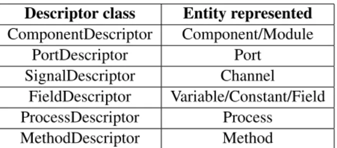
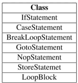
2.1 List of tasks performed during the project . . . 8 3.1 SystemCspecific data types . . . 13 4.1 Examples of System# element descriptor classes and entities represented . . . 29 4.2 Examples of System# classes representing statements and control flow structures 30 4.3 Correspondence table between System# and SystemC data types . . . 35 6.1 Comparison of average execution time in System# and generated SystemC . . . . 58 6.2 Comparison of average execution time in VHDL and generated SystemC . . . 58 6.3 Co-Simulation average execution time for Bus Arbitration and Squirrel-Cage
sys-tems . . . 62 6.4 Messages flow for the Bus Arbitration system co-simulation . . . 64 6.5 Co-Simulation average execution time for Bus Arbitration, considering the
shared-clockand split-clock situations . . . 65 6.6 Messages flow for the Squirrel-Cage system co-simulation . . . 65 6.7 Co-Simulation average execution time for Squirrel-Cage, considering the
shared-clockand split-clock situations . . . 65
Abreviaturas e Símbolos
AST Abstract Syntax Tree
CIL Common Intermediate Language DC Direct Current
DES Discrete-Event Simulation EME Electric Motor Emulator ESL Electronic System Level
FPGA Field-Programmable Gate Array FSM Finite State Machine
FZI Forschungszentrum Informatik- Research Center for Information Technology HDL Hardware Description Language
HiL Hardware-in-the-Loop HLA High-Level Architecture HLS High-Level Synthesis I/O Input/Output
IP Intellectual Property ISS Instruction Set Simulator LP Logical Process
MIMD Multiple Instruction, Multiple Data P-HiL Power Hardware-in-the-Loop RTL Register-Transfer Level SD Simulation Domain
SIMD Single Instruction, Multiple Data
SLDL System Level Description/Design Language SoC System-on-Chip
TNLE Time-to-Next-Local-Event TNRE Time-to-Next-Remote-Event
Chapter 1
Introduction
In this introductory chapter, the context as well as the motivation which sustain the developed work are presented. A document structure description is also given in the end of the chapter.
1.1
SimCelerate project contextualization
This Master dissertation is part of the Integrated Master in Electrical and Computers Engineering (Mestrado Integrado em Engenharia Electrotécnica e de Computadores ) from the Faculty of Engi-neering of the University of Porto (Faculdade de Engenharia da Universidade do Porto). The work covered by this dissertation is within the scope of the SimCelerate project which results from a partnership between FZI - Forschungszentrum Informatik - Research Center for Information Tech-nology(based in Karlsruhe), ITI GmbH (based in Dresden) and SET Powersystems GmbH (based in Wangen). Before diving on the details about the developed work, a general contextualization of the SimCelerate project will be done.
In the automotive industry, testing electrified drive-trains of a vehicle is a very important part regarding the device safety. So, during development phase, electrified drive-trains are exhaustively tested in order to figure out whether the system meets the desired requirements and behaviour. One can test an algorithm using a purely mathematical model describing the system behaviour. How-ever, another approach has gained popularity in the automotive industry within the last 25 years: Hardware-in-the-loop (HiL) simulation [5]. Shortly, HiL simulation consists in the integration of a part of the real hardware in the simulation loop. HiL simulation also makes it possible to perform real-time simulation. Considering the case of testing an electronic motor controller, one can use the real controller, in order to achieve a higher accuracy, and replace the surrounding envi-ronment (motor and vehicle mechanics) by a virtual device - the Electric Motor Emulator (EME). Usually, the starting point for the creation of an EME is a Modelica description of the system one wants to simulate. Modelica [6] is an object-oriented, equation-based language intended for modelling of complex systems of different kinds (e.g. electrical, electronic, mechanical, control, thermal, hydraulic). In Modelica, models are mathematically described using differential, alge-braic and discrete equations. A key difference of Modelica regarding to typical object-oriented
2 Introduction
programming languages has to do with the compilation process: Modelica classes are translated into objects and afterwards theses objects are operated by the simulation engine. The industry pro-vides EMEs covering synchronous, asynchronous and DC machines with power up to 300kW [7]. These emulators also allow the recreation of the high voltages and currents (Power Hardware-in-the-loop, P-HiL), running at sampling rate up to 800kHz. Consequently, a real-time simulation of an electric motor running at a cycle time around 1µs is needed. This real-time requirement is hard to achieve with processor-based systems due to the unpredictable time overhead introduced by the I/O operations required for the HiL simulation. So, the state-of-the-art emulators execute the motor simulation on an FPGA. The great concern regarding to the Modelica-to-FPGA design flow is the high engineering effort needed to execute it. Consequently, the entire process becomes very expensive. It was in this context that the SimCelerate project arose. This project focuses on the development of an automated approach for transforming a Modelica model into an hardware design for FPGAs. The main emphasis is given to the domain of electric motor controllers. The key aspects of this project are:
• Design of hardware architectures for efficient real-time calculation of numerical simula-tions;
• Identification and implementation of domain-specific hardware modules (e.g. parallel solu-tion of Systems of Linear Equasolu-tions);
• Design of an integrated transformation process.
In order to face the challenge of automating the Modelica-to-FPGA design flow, one frame-work was developed by FZI: System#. This frameframe-work is one of the most important domains studied and used during the Master dissertation development. As a first reference, System# is a .NET library which is intended for both high-level synthesis of physical simulation for FPGA-based real-time execution and for the description of real-time embedded systems.
1.2
Motivation
The general approach used in SimCelerate project for the Modelica-to-FPGA procedure comprises 3 main stages: Modelica compilation, high-level synthesis and FPGA design implementation [1]. High-level synthesis is executed by System# and during this stage a complete RTL system spec-ification is produced. Then, it can be used for system verspec-ification and simulation or synthesiz-able VHDL generation. Before FPGA system implementation, the design should be iteratively simulated and verified. It is possible to do it using VHDL or System# but both of them are not satisfactory in terms of performance. As it is a recent framework, System# can still be improved in order to render a better simulation performance. Indeed, some work is currently being done at FZI seeking for these improvements. However, it would be also beneficial to have an alternative to VHDL and System# simulation. In turn, this alternative should be integrated in the high-level synthesis tool - System# - so that the design flow is kept automated.
1.3 Document Structure 3
Although System# is being referred as a high-level synthesis framework it is also intended for the description of real-time embedded systems, as stated in the end of the previous section. System#provides constructs and proper design rules needed for designing and modelling complex electronic systems from the scratch. In other words, System# can also be viewed as a system level description language(SLDL) based on the .NET framework. In the past decades, technological progresses in the field of embedded systems made it possible to produce more complex systems which wrap different subsystems. These subsystems can vary in function and form (hardware or software) - heterogeneous systems.
In this context, SLDLs arose as well-suitable platforms for designing, modelling and simulat-ing complex electronic systems. Several SLDLs are available nowadays, besimulat-ing SystemC the most popular and accepted one among industry and academy. However, given the increasing complexity and heterogeneity of embedded systems, it is plausible that the different system subcomponents are modelled and simulated individually, using different languages or frameworks. Nevertheless, global simulation and verification of heterogeneous systems assumes particular importance dur-ing the project and production cycle. So, interoperability and co-simulation mechanisms between different subsystems composing a broader system are needed. The targeted SLDLs in this Master dissertation are SystemC and System#.
1.3
Document Structure
Apart from the introductory chapter, this document includes other seven chapters. In Chap-ter 2, a description of the problem and objective which sustain the MasChap-ter Dissertation are pre-sented. Furthermore, a short overview of the methodology adopted is shown together with a list of tasks performed and technologies used. A bibliographic revision is made in Chapter 3, presenting the fundamental knowledge required and the state-of-the-art of co-simulation and in-teroperability between discrete-event simulators. Chapter 4 and Chapter 5 target the implemented work within this Master Dissertation: SystemC code generation from System# projects and co-simulation/interoperability between SystemC and System#, respectively. After, the implemented work is evaluated and results are shown - Chapter 6. Chapter 7 focuses on conclusions, contribu-tions from the developed work and future work proposals. Then, Appendix A shows some code examples for co-simulation. Finally, bibliographic references are presented.
Chapter 2
Problem and Objectives
This chapter addresses the problem targeted by this Master dissertation, its objectives and general considerations on the methodology adopted. First, a more detailed description of the problem is presented. Then, the intended objectives of this work are exposed. Finally, remark about method-ology, tasks to perform and technologies and tool used during the developed work are presented.
2.1
Problem Description
In section 1.2, the motivation behind the developed work was shortly presented. In this section, a more detailed overview of the targeted problem is exposed.
In figure 2.1, there is an overview of the SimCelerate project approach for the Modelica-to-FPGA design flow. It is possible to identify three main stages.
The first stage culminates with the Modelica compilation, resulting in a calculation rule which includes all computations required to execute a single integration step. The Modelica compiler employs in-line integration [8] to produce a compact calculation rule suitable for hardware map-ping. In this case, the intermediate representation resulting from Modelica compilation is not C code, but a XML-based format consisting of: system interface description, control and dataflow graph in assembler-like language and special support for fixed-point arithmetic and mathematical functions.
It is this intermediate representation produced by the Modelica compiler which is the input of the second stage of the Modelica-to-FPGA design flow: high-level synthesis. This stage is performed by System#. After assigning instructions to clock cycles, binding them to hardware resources and allocating data transfers to intermediate storage registers, a control path is con-structed. In turn, this control path can provide a complete RTL specification of the system intended for simulation. This RTL specification can be used for verification and simulation as well as for synthesizable VHDL generation.
The third and last stage of the design flow consists of simulation and verification of the system description provided by the high-level synthesis, and also the design implementation on an FPGA. There are two alternatives to perform system simulation and verification. One consists of taking
6 Problem and Objectives Cycle-accurate specification RT-level specification w/o control path Complete RTL specification Intermediate represen-tation VHDL & IP core generation Synthesizable design
Synthesis Netlist Implementation
FPGA bitfile
FPGA vendor-specific toolchain
Simulation/ Verififation
Model Flattening and
expansion Unsorted differential equations Modelica compilation Scheduling, Allocation, Binding Interconnect allocation Control path construction
Processing inside SimulationX
High-level synthesis Interface configuration Model and interface Synthesis configuration IP core repository
Figure 2.1: Modelica-to-FPGA design flow [1]
the previously produced RTL specification and simulating it using System#. The other consists of performing VHDL code generation from the RTL specification (using System#) followed by VHDL-based simulation and verification.
One practical problem arises from the described design flow. Before integrate the design on an FPGA, it is desirable to be able to simulate and verify it in an expedited manner. However, the VHDL-based simulation is slow and requires user interaction. On the other hand, the System#-based simulation can be done automatically but it is even slower, as it is a recent framework not fully optimized.
One possible approach to address this problem can be the automatic generation of a SystemC model which is used for exhaustive numerical verification. Once the verification results are ac-ceptable, VHDL code is generated and a new verification procedure is done but now focused on aspects such as timing and I/O operations. The advantage of using a SystemC model for simu-lation and verification resides on the higher performance of SystemC simulator, compared with System#/VHDL-based simulation, and only a C++ compiler is required to do so. In order to keep the complete design flow automated, the SystemC code generation should be integrated in the high-level synthesis tool - System#.
From a SLDL domain perspective, another problem arises. The increasing complexity of embedded systems may require the use of different languages or Models of Computation (MOC) to design a whole heterogeneous system. If one wants to simulate and verify the whole system, a homogeneous approach can be taken by using a single language to describe the whole system [9] [10]. However, it is hard to have a language able to cover the semantics of all MOCs in a given
2.2 Objectives 7
embedded system.
The heterogeneous approach describes the models in their native languages, keeping the con-ceptual differences of each domain [11]. Considering a system composed by SystemC and Sys-tem#modules, the challenge consists of developing and validating concepts of SystemC/System# co-design and co-simulation.
Additionally, SystemC has a large community of users and associated software tools, contrast-ing with the recent System#. So, some degree of interoperability between both domains would clearly improve System#’s perception.
2.2
Objectives
Considering the problem described before, the work developed within this Master Dissertation aims the development and validation of co-design and co-simulation concepts between two SLDLs - SystemC and System# - in order to achieve some degree of interoperability between projects and/or components designed in both frameworks. Thereafter, this Master dissertation has two main objectives:
• Implement SystemC code generation from System# projects: from a high-level synthesis tool perspective, System# must be able to automatically generate SystemC code from an elaborated System# model. As the generated code may be used to speed-up the simulation and verification loop, it should provide a correct description of the original system and thus, produce correct simulation results;
• Develop a SystemC/System# co-simulation mechanism: both simulation domains - Sys-temC and System# - must be able to communicate and transfer data related with events affecting the remote domain. Apart from it, the co-simulation mechanism requires time synchronization between the simulation domains in order to the coherency and accuracy of the process. This way, the co-simulation environment comprises a communication mecha-nism and a synchronization algorithm.
2.3
Methodology
Having in mind the objectives stated in section 2.2, a brief description of the methodology used to attack the problems referred in section 2.1 is now presented.
As stated before, the SystemC code generation engine must be integrated in System# platform. So, the chosen approach was the study of the VHDL code generation engine already present in System#and its adaptation towards SystemC code generation. The study of the code generation engine required the understanding of how concepts like components, ports, channels or processes are internally represented in System#. The particular study of the VHDL code generation proce-dure was also useful through the identification and comparison of common elements and concepts between VHDL and SystemC, and the verification of how the VHDL syntax for those elements or
8 Problem and Objectives
concepts is produced. However, as SystemC is a broader language than VHDL, the implementa-tion of procedures for the syntax generaimplementa-tion of specific SystemC concepts was also required. Other important issues were the data types equivalence and compatibility.
Regarding to System#/SystemC co-simulation, the problem was divided in two parts: commu-nication between SystemC and System#and synchronization between SystemC and System#. The first part has to do with the IPC mechanism used and the characteristics of the data transferred between both domains. The second part is related to the algorithm that controls and synchronizes the simulation flow in both domains.
When deciding which approaches to choose for both communication and synchronization problems, a trade-off between available work time, complexity and performance was taken into account. So, a review of the available APIs for IPC mechanisms in the used operating system was done. With respect to simulation coupling and synchronization, it was decided to avoid the modification of the SLDLs kernels, for sake of compatibility between different versions. Given the time constraints imposed for the Master dissertation development, the adopted synchronization was of conservative nature. On the other hand, this approach does not require as many memory and processor resources as the optimistic approaches.
2.4
List of Tasks
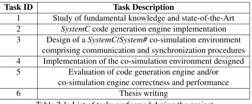
The Table 2.1 enumerates and describes the tasks which composed the work developed. These generic tasks formed a guideline to better organize and manage the available work time.
Task ID Task Description
1 Study of fundamental knowledge and state-of-the-Art 2 SystemCcode generation engine implementation 3 Design of a SystemC/System# co-simulation environment
comprising communication and synchronization procedures 4 Implementation of the co-simulation environment designed 5 Evaluation of code generation engine and/or
co-simulation engine correctness and performance
6 Thesis writing
Table 2.1: List of tasks performed during the project
2.5
Technologies and Tools
For the development of this Master dissertation, a computer equipped with a Microsoft Windows operating system was used. As the two main domains of this project, the SLDLs System# and SystemC (version 2.3) were tools exhaustively used. The use of System# also requires the use of the .NET framework. The Windows APIs for IPC was employed.
2.5 Technologies and Tools 9
The IDE used for programming tasks within this project was the Microsoft Visual Studio (2012 edition). At the same time, the documentation related with this Master dissertation was produced in LaTex.
Chapter 3
Background Information and State of
Art
In this chapter, fundamental knowledge about SLDL (particularly SystemC and System#) and discrete-event simulation is presented. Co-simulation and interoperability of discrete-event simu-lators state-of-the-art and related work is also referred.
3.1
System Level Description Languages
Recent trends in SoC projects move towards an increasing complexity of systems composed by hardware and software components and the need of third-party IP integration. Under this scenario, the traditional hardware/software co-design approach, in which languages like C/C++ are used for software design and HDLs are used for hardware design, introduces a big separation between both design levels. This situation is difficult to overtake if one wants to generate synthesizable code. This way, the gap between the system complexity and the engineering effort required for the system conception - productivity gap - substantially increases.
It was in this context SLDL emerged as tools or frameworks intended for complex electronic systems modelling, design and verification. These languages provide a suitable environment for the co-design of hardware and software components in an heterogeneous system, supplying appro-priate data types, libraries and simulation mechanisms, as well as supporting several abstraction levels like RTL (typically used by HDLs) and ESL.
Several SLDLs were presented and introduced over last years, being SystemC the most widely used. SpecC [12] is another SLDL example. Although they are closer to hardware verifica-tion languagesthan to SLDLs, platforms as SystemVerilog [13], OpenVera [14] and e [15] try to present some typical features from object-oriented programming languages, while keeping typi-cal properties from HDLs [16]. For example, in SystemVerilog there is an extension of Verilog functionalities, being Verilog one of the most largely used HDLs together with VHDL.
12 Background Information and State of Art
Recently, taking advantage of the features provided by .NET [17] software development frame-work, specially the ability of a program to observe and/or modify its structure in run time - reflec-tion- [18] new SLDL proposals have been presented. Examples of these new SLDLs are System# and ESys.NET [19].
In the scope of this Master dissertation, SystemC and System# are the studied and used SLDLs.
3.1.1 SystemC
SystemC [20] consists of a ANSI C++ library intended for electronic systems design, modelling and verification. Beyond inherited features from C++ (Object-oriented language) which allow software modelling, SystemC also provides adequate concepts and constructs for hardware mod-elling (modular hierarchy, notion of time and concurrent execution, hardware data types) and system architecture modelling (interfaces and communication channels, models with several ab-stractions levels - Gate level, RTL and ESL).
According to the report elaborated by Doulos [21], SystemC is mainly used in performance modelling, architectural exploration, Transaction-level Modelling [22] and hardware/software co-simulation. Nevertheless, SystemC is also widely used for verification and testbench creation, surpassing some languages/platforms specially directed for this kind of tasks, as Vera and e.
The SystemC announcement and presentation was done in 1999 by the Open SystemC Initiative - OSCIand since then, the popularity of this tool considerably increased. This is visible due to the big community of users, both in industry and academy, and the variety of support tools available. Several elements contributed to the big SystemC popularity. Besides of having been accepted as an IEEE norm (IEEE 1666 R), SystemC includes an Open Source simulator which only requires
a C++ compiler to run (ensuring high flexibility regarding to the Operating System in which it is used) and is easily integrable with C/C++.
Next, some contents extracted from [20] will be exposed, aiming a better understanding of SystemCstructure and functionalities.
In order to effectively deal with systems complexity, SystemC calls upon the separation be-tween functionality (specification level) and architecture (implementation level) and bebe-tween com-putation and communication. Towards the comcom-putation/communication separation, comcom-putation is performed by processes associated to system modules, while communication is ensured by com-munication channels. The connection between both domains is done by the connection of ports, contained in modules, to interfaces provided by channels.
SystemClibrary includes classes which fall in one of four categories: Core Language, Prede-fined channels, Utilities and SystemC Data Types.
Among the most used functional constructs in SystemC, one can highlight: modules, processes, ports, events, channels and interfaces.
A module (macro SC_MODULE) is the basic structural block of a system described in Sys-temC. A generic system is constituted by a hierarchy of modules which are connected. A module can contain ports, processes, events, channels and other modules.
3.1 System Level Description Languages 13
Processesdescribe a module functionality and present concurrent execution. There are three types of processes: SC_METHOD (similar to C++ functions; executes when a certain condition is verified and its execution cannot be interrupted), SC_THREAD (executes only once, but can be kept active through the inclusion of an infinite loop; can be interrupted) and SC_CTHREAD (its execution is similar to SC_METHOD one, but it is triggered by clock impulses).
Portssupply an abstraction which permits the isolation of a module implementation from the surrounding environment. They allow the communication between modules or channels and can be unidirectional or bidirectional. The most common port types are the unidirectional built-in ports sc_in and sc_out. Still, it is possible to create and define ports according to the project needs. Events(sc_event) consist of flexible low-level synchronization primitives. They can be used to build other forms of synchronization.
SystemC provides some built-in channels which can model signals (sc_signal), clock signals (sc_clock), mutexes (sc_mutexes), semaphores (sc_semaphore) or FIFO queues (sc_fifo). Together with these primitive channels, interfaces which define a set of channel access methods are avail-able, making channels useful for communication between modules. There is also the possibility to define hierarchic channels, in order to model more complex behaviours. Shortly, a hierarchical channel consists of a module which implements methods declared in an interface.
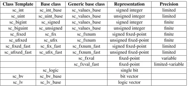
With respect to data types, SystemC supports native C/C++ data types, as well as specific data types suitable to system modelling: integers of variable dimension, logic values, logic values vectors or fixed-point numerical values. Table 3.1 reproduces a table from [20] which shows the SystemCspecific data types.
Class Template Base class Generic base class Representation Precision sc_int sc_int_base sc_values_base signed integer limited sc_uint sc_uint_base sc_values_base unsigned integer limited sc_bigint sc_signed sc_values_base signed integer finite sc_biguint sc_unsigned sc_values_base unsigned integer finite sc_fixed sc_fix sc_fxnum signed fixed-point finite sc_ufixed sc_ufix sc_fxnum unsigned fixed-point finite sc_fixed_fast sc_fix_fast sc_fxnum_fast signed fixed-point limited sc_ufixed_fast sc_ufix_fast sc_fxnum_fast unsigned fixed-point limited sc_fxval fixed-point variable sc_fxval_fast fixed-point limited-variable
sc_logic single bit
sc_bv sc_bv_base bit vector
sc_lv sc_lv_base logic vector
Table 3.1: SystemC specific data types
The execution of a SystemC application comprises two fundamental steps: elaboration and simulation. During elaboration, a hierarchical structure of the system is created, including the in-stantiation of modules and channels, as well as the connection between ports and channels. Once the structure is created, it cannot be changed during the rest of elaboration and simulation. The
14 Background Information and State of Art
simulation is performed by SystemC scheduler. During this step, the scheduler manages the ex-ecution of different processes, creating the illusion of a concurrent exex-ecution. The beginning of simulation is triggered by calling the function sc_start(). To perform elaboration and simulation, it is required to run the application code and the SystemC simulation kernel code, which con-sists of a part of classes from SystemC library where the scheduler and fundamental elaboration functionalities are implemented.
SystemCsimulation kernel implements a discrete-event simulation system and presents a non-preemptive task manager mechanism - cooperative multitasking. This simulation kernel presents some features similar to the ones from VHDL simulation mechanism like, for example, the de-terministic behaviour of the simulation (the simulation result must not depend on the order by each process is executed, for a given simulation step). The basis for the deterministic behaviour is the concept of delta cycle. A delta cycle consists of a scheduler control cycle comprehend-ing an evaluation phase followed by an update phase. It is the alternation between computation (evaluation phase) and communication (update phase) that guarantees the deterministic behaviour. A delta cycle is a zero-time step. In other words, it does not contribute to the simulation time advancement.
The simulation features referred before are typical from hardware simulation. However, as SystemC aims to be a language suitable for hardware/software systems modelling, its simulation kernel also exhibits some non-deterministic features which allow correct software modelling. The use of events and notifications between processes and primitive channels intended for critical sec-tions access control are examples of features which add non-determinism to SystemC simulation kernel.
Then, a brief description of each execution step performed by SystemC simulation kernel is presented [23]:
• Initialization: execution of all processes (except SC_CTHREADs) in an undefined order until they reach the first synchronization point (if any);
• Evaluation: a process ready to run is selected and its execution is resumed. This can cause immediate event notifications which may turn some processes ready to run;
• The previous step is repeated until there are no more processes ready to run;
• Update: execution of all pending update requests (calls to update()), as a result from calls to request_update() made during last evaluation phase;
• If event notifications made during current delta cycle exist, processes are inspected in order to know which ones are ready to run due to all those events. Proceed to another evaluation phase;
• If there are no timed events, simulation is finished. Otherwise, simulation time is advanced to the time of the earliest pending timed event notification;
3.1 System Level Description Languages 15
• Determination of which processes are ready to run as consequence of all timed events (cur-rent time) and execution of another evaluation phase.
Below, figure 3.1 presents a flowchart illustrating the scheduler execution.
Figure 3.1: SystemC scheduler operation flowchart [2]
3.1.2 System#
As stated in Section 1.2, System# is a high-level synthesis framework and also a SLDL. In this section, the main features and constructs of System#, as an SLDL, will be targeted.
System# consists of an open source C# library (.NET framework) which provides structures suitable to the description and simulation of real-time embedded systems. Being a platform which addresses the design of FPGA-based systems, System# includes a mechanism for synthesizable VHDL code generation. This SLDL supports RTL descriptions as well as some synthesizable TLM concepts. System# was presented in 2012 [4] by the Embedded Systems and Sensors En-gineering (ESS)research division of FZI, within the scope of SimCelerate project. Thus, it is a recent tool and, consequently, is not so mature as SystemC.
16 Background Information and State of Art
Regarding to the synthesizable VHDL generation, System# makes use of .NET framework typical features - reflection and decompilation of assembly code (CIL) - to build an AST, taking into account the system structure. In turn, the built AST obeys to a Document Object Module -DOM - for describing component-based reactive systems: Sys-DOM. The transition from an AST to VHDL code is done through an unparsing process.
Modelling a system with System# is similar to do it with SystemC. There is also the base concept of separation between computation (modules) and communication (channels). As it was previously done with SystemC, basic concepts and functionalities which allow systems description and modelling with System# will be presented. Most of these contents were extracted from [24].
A system described in System# typically presents a hierarchy of components which represent and describe the operation of some system parts. A component consists of a C# class derived from Component(namespace SystemSharp.Components) and can contain instances of other components in the system.
The interaction between a component and the surrounding environment is done through ports. In System#, ports are actually C# properties. Examples of input and output ports are In<data_type> and Out<data_type>, respectively. Ports merely represent a communication interface between a component and the exterior. In order to perform this communication, ports must be connected to channels.
By storing information exchanged between ports, a channel models the concept of communica-tion and is represented in System# by the abstract class Channel. This class is used in the definicommunica-tion of every kind of channel. One of the most common channels in System# is Signal<data_type>, which represents a signal.
As in SystemC, a process describes the module functionality. In a system, processes execute concurrently. There are three types of processes in System#: Triggered process (executes due to some event(s) described in a sensitivity list; it consumes no simulation time; its registration is done through AddProcess()), Threaded process (starts its single execution in the beginning of simulation; can be pause due to some event and is registered with AddThread()) and Clocked thread (a special thread intended for synthesizable synchronous FSMs modelling; is sensitive to an edge of a clock signal; AddClockedThread() registers this kind of processes).
System#also provides data types suitable for embedded systems modelling, namely bit-accurate data types and resolved logic. These hardware data types belong to the SystemSharp.DataTypes namespace.
Resolved logic data types in System# are StdLogic and StdLogicVector. StdLogic is a nine-value data type equivalent to the std_logic data type in VHDL and StdLogicVector is simply a vector whose elements are from StdLogic type.
Regarding to bit-accurate data types, arbitrary-length integers can be represented by the types Signedand Unsigned, while fixed-point arithmetic is provided by data types SFix and UFix.
As in SystemC, the execution of a System# application includes elaboration phase and simu-lation phase. During elaboration, the system design is not only prepared for simusimu-lation, but also for analysis and program transformation (for example: VHDL code generation). This phase is
3.1 System Level Description Languages 17
triggered by the instruction DesignContext.Instance.Elaborate() and after that, the system struc-ture or functionality cannot be changed. Simulation is performed by the instruction DesignCon-text.Instance.Simulate(). An example for the call of Simulate/Elaborate functions is presented in Figure 3.2 System# simulation kernel also performs discrete-event simulation and its operation is similar to the one in SystemC. The main difference resides in the management of thread pro-cesses: while in SystemC we have cooperative multitasking, System# maps thread processes to tasks through the Task Parallel Library from .NET framework. So, System# simulation kernel assume characteristics of a parallel discrete-event simulator (PDES).
Figure 3.2: Calls to Elaboration and Simulation in System#
In terms of performance, System# simulation is slower than SystemC one. Being System# a young tool, some efforts within SimCelerate project are currently in course aiming a better simulation performance. At the time this document writing, some work on using the new C# 5.0 features to improve System# performance is in progress.
Apart from taking advantage of .NET features like reflection and providing VHDL code gen-eration, System# presents other distinctive features comparing with other SLDLs: synthesizable sequential descriptions and IP-based Design. The first of these features is related with the usual need for FSMs specification in FPGA design. Sometimes this task can become troublesome. Fac-ing this, System# enables the generation of synthesizable FSMs from clocked threads. If one wants to derive a FSM from a cloked thread, the C# attribute TransformIntoFSM must be placed before the method implementation.
18 Background Information and State of Art
Usually, FPGA vendors furnish their FPGA design tools with an IP core library. Having this IP cores in mind, the designer have to customize parameters and store them in a proprietary file format. Right now, System# only supports a limited set of cores from the Xilinx FPGA toolchain. However, System# can be extended in order to support other FPGA vendors tool-chains.
3.2
Discrete-Event Simulation
During the process of designing and evaluating a system, one may want to know how the system will react under certain circumstances in order to figure out if it serves the purposes for what it is being designed. One of the most broadly used techniques of imitating the operation of a system over time is simulation. To simulate a system, an abstraction is needed and it usually takes the form of a model. In turn, a model describes and represents the target system through mathematical or logical relationships. Often during a system project, there is a big interest in studying the system response to time constraints. This way, the evolution of the system state must be well defined in the model.
If the state of the system one wants to simulate changes continuously over time, it is classified as a continuous system. On the other hand, if the system state only changes at specific points of time, it is called a discrete system. There are also hybrid systems comprising continuous and discrete components.
Taking into account how the system state evolves over time, suitable simulation progression of time must be implemented. Therefore, there are time-driven (or time-stepping) simulation and event-driven(or discrete-event) simulation. In the former, time is incremented and measured in small steps, giving the illusion of a continuous time evolution; in the later, time jumps through different points of time (events), making the system operation to be a chronological sequence of events. By their definitions, it is possible to discern that time-driven simulation suits better to continuous systems, whereas discrete-event simulation suits better to discrete systems.
Due to the context of this dissertation and the SystemC/System# simulation nature, special attention will be given to discrete-event simulation (DES).
A discrete-event simulation has 3 main elements: state variables, an event-list and a clock variable[25]. The state variables store information about the state of the system. The event list is a data structure basically consisting of a priority queue that orders events according to their scheduled time and the clock variable keeps track of current simulation time.
The discrete-event simulation operation is described by the simulation cycle. Though it may vary from simulator to simulator, there is a common basic execution structure which consist of a loop. In this loop, the simulator repeatedly extracts an event with the smallest timestamp from the event list, updates the clock variable to this event timestamp and then processes the event. The event processing can change the model state and give origin to future events that may be inserted into the event list. This loop continuously executes until an ending condition is met.
Traditional discrete-event simulators are characterized by presenting a cooperative multitask-ing (also referred as non-preemptive multitaskmultitask-ing), meanmultitask-ing that a process/thread can self-interrupt
3.2 Discrete-Event Simulation 19
and voluntarily give control to other process/thread. This approach highly simplifies the commu-nication through events and the access to variables in shared memory. On the other hand, the available parallelism in recent multi-core CPUs is wasted [26], as well as the possibility to per-form simulation through different computers spatially separated.
As systems complexity grows, issues related with simulation speed and memory usage arise. In order to face these challenges, parallel and distributed DES became an interesting and rele-vant research area combining modelling and simulation concepts with high-performance comput-ing [27]. Several surveys, reviews or books about this topic were published by different authors like Misra [28], Fujimoto [25], Liu [27] or Ferscha [3].
Although the terms parallel DES and distributed DES are sometimes used indiscriminately, some authors make a distinction between both concepts. According to Ferscha [3], parallel DES refers to a SIMD environment in which a set of processors execute similar operations (fetched from a central control unit) on different data. This central control unit ensures the synchroniza-tion between independent computasynchroniza-tions. On the other hand, distributed DES is characterized by MIMD environment. In this case, the system event structure is decomposed and different pro-cesses operate "asynchronously in parallel". Here, communication between propro-cesses is required with the intention of exchange data and correctly synchronize each process.
Fujimoto [29] makes a slightly different distinction: a parallel DES consists of the execution of a single simulation program through a group of tightly coupled processors, as in a shared mem-ory multiprocessor architecture; in a distributed DES there is an execution of a single simulation program on a set of loosely coupled processors, as in a computer network.
Fujimoto also refers an alternative approach which targets the execution of several, indepen-dent simulations concurrently on different processors - replicated trials. Although it is a simple approach, it has the disadvantage of not providing any kind of speed-up and of requiring each pro-cessor to have enough memory space for simulation. It is also an approach which is not adequate for interactive environments.
Usually, in a parallel or distributed DES the events are distributed among a collection of com-municating logical processes (LPs) in order to divide a global simulation task and exploit paral-lelism through the concurrent execution of these processes. Ferscha [3] classifies these simulation strategies as logical process simulation (LP simulation) and presents a basic architecture of it (Figure 3.3).
LP simulation is easily understandable if one views a simulation as a set of events characterized by a temporal coordinate (timestamp) and a spatial coordinate (the location of the state variables affected by the event). This space-time view of simulation was presented in 1989 by Chandy and Sherman [30]. The space-time spectre is then divided into different regions which are assigned to different LPs. Each LP keeps and maintains its own local clock and event list, and executes local eventsthrough its Simulation Engine. The execution of local events can affect other LPs, generating remote events. These remote events also need to be processed by the affected LPs. So, an LP needs to exchange their local data in order to perform event notification regarding to other LPs and also to let them know about its local simulation time. The Communication System makes
20 Background Information and State of Art
Figure 3.3: Architecture of an LP simulation [3]
this data sharing between LPs possible. An LP can access the Communication System thanks to the Communication Interface attached to the Simulation Engine.
In order to guarantee the logic coherency and consistency of a DES, events have to be pro-cessed in a non-decreasing timestamp order, because an event with a smaller timestamp can po-tentially affect the system state and consequently also affect future events. This DES requirement is called causality constraint and involves a total ordering of events.
In LP simulation, the global event list is spread among the LPs local event lists. Although the Simulation Engine of each LP can ensure the causality constraint for all local events - local causality constraint- it cannot predict the arrival of remote events from other LPs or the timestamp of these remote events. This way, it can happen that, while an LP is processing a local event, a remote event with a smaller timestamp arrives. So, this remote event with a smaller timestamp will be processed out of timestamp order, breaking the causality constraint for that LP. In other words, not processing events on timestamp order can cause "the computation for one event to affect another event in its past" [29]. These failures are called causality errors and the problem caused by these errors is the synchronization problem. Liu [27] shortly describes the challenge arising from the synchronization problem as "the difficulty of preserving the local causality constraint at each LP without the use of a global simulation clock". In turn, Fujimoto [25] points to the complexity and high data dependency of the constraints that command the order in which operations have to be performed relative to each other.
To address the synchronization problem, a collection of algorithms has been developed - syn-chronization algorithms. A review of some of these algorithms will be present in the next section.
3.3 Synchronization in Discrete-Event simulation 21
3.3
Synchronization in Discrete-Event simulation
Synchronization in parallel/distributed DES can be achieved through two algorithm categories: conservativeand optimistic. Conservative synchronization algorithms do not allow the occurrence of any causality error by blocking an LP from processing its next event until it is certain that this event will not generate out-of-order event processing due to later events from other LPs. On the other hand, optimistic synchronization algorithms allow causality errors to occur. However, this class of algorithms has the ability to detect causality errors and recover from them, by invoking a rollbackmechanism. Rollback requires state saving and recovery mechanisms.
3.3.1 Conservative Synchronization
Chandy and Misra [31], as well as Bryant [32] independently presented the first parallel/distributed DES algorithm which is commonly known as the CMB algorithm. In this algorithm, LPs are con-nected via directional links used to exchange events between LPs in a non-decreasing timestamp order. For each incoming link at an LP there is an input queue used to place the received events. A clock variable is attached to each input queue and its value is the timestamp of first event in the queue, if any. If the queue is empty the clock variable assumes the value of the last processed event, which is initially zero. An LP iteration first selects the input queue with the smallest clock value and then processes its first event. If the queue is empty, the LP blocks until the arrival of an event in that queue. Once it arrives, the LP execution continues to the next iteration.
Given the nature of this algorithm, the occurrence of a blocking cycle among all LPs is possi-ble, driving to a deadlock situation. To avoid these situations, CMB algorithm uses null messages which do not represent any event but only transport a timestamp. This timestamp can be seen as a guarantee from the sending LP that it will not send futures events with a timestamp smaller than the null message timestamp. The LP’s input queue which receives a null message can advance its clock variable and notify other LPs about this time advancement (also using null messages). So, the null message protocol is a deadlock avoidance mechanism. There are also some protocols which allow deadlock to occur, being this occurrences detected and recovered [33].
The null message synchronization remarks to a fundamental property common to all conser-vative synchronization algorithms - lookahead. It is related with the capacity of determining if the next event in a simulator is safe to process. According to Liu [27], lookahead is the "amount of simulation time that an LP can predict into the simulated future". Nicol [34] presents another definition of lookahead: considering two processes, p and q, process p has lookahead regarding to process q if, being the simulation clock of p at time s, process p can determine that there is no way it will insert/delete an event in/from process q event list with timestamp t > s. Apart from this definition, Nicol also presents some subtleties of lookahead.
There are other conservative synchronization protocols beyond the null message protocol. In [35] and [36], Nicol and Reynolds present the appointment protocol. It is an adaptation of the null message protocol, but replaces the null messages for appointments which consist of a promise by the sending LP to not send any message with a timestamp larger than the appointment
22 Background Information and State of Art
time. Although it seems to be the same mechanism as the one from the null message protocol, there is one main difference. A null message is enqueued and is only processed when the LP’s clock reaches the null message timestamp. In contrast, the appointment information can be imme-diately used by the receiving LP. Thus, at any time, an LP can access the appointment information in order to calculate lookahead and eventually notify other LPs.
Based on the appointment algorithm and taking into account the LP topology, the time-of-next-event algorithmwas presented by Groselj and Tropper [37]. It computes the lower bound on the time of the next message sent from one LP to the other - link time. To do so, the algorithm considers the time of next event in each LP, existing link times, the minimum delay an LP takes to process a message and the shortest path algorithm. The link times can be viewed as appointments. Until now, the synchronization algorithms presented are asynchronous in the sense that each LP locally computes its lookahead, based on its data and data received from other LPs. However, there are some algorithms in which there is a global lookahead calculation across all processors in order to identify, for each LP, a time instant up to which it is safe to advance. The bounded lag algorithm[38] is an example of this class of algorithms. Assuming a static LP topology, a time interval B - lag - is used to compute a sphere of influence: a group of LPs that might affect an LP within B simulation time units. The LPs belonging to the sphere of influence need to be considered to determine if a certain LP with timestamp between the current simulation time T and T+B can be processed in a safe way.
Another example of a synchronous algorithm is the conditional event approach [39] presented by Chandy and Sherman. In a sequential simulation, all the events on an event list, except the one with the smaller timestamp, are conditional. It means that the only event which cannot be preempted, removed or changed - unconditional - is the earliest event and the simulator can safely advance to its timestamp. In a parallel/distributed simulation, the event list from an LP can have conditional events, unconditional events and events which do not affect other events in this local event list. However, the event with the smallest timestamp in one LP is not necessarily uncondi-tional because it can be affected by events with a smaller timestamp from other LPs.
Through the conditional event algorithm, each LP determines its conditional event with the smallest timestamp and delivers it to a global reduction operation which returns the timestamp of the earliest conditional event in the whole system. This returned timestamp defines the simulation time up to which all LPs can concurrently simulate.
3.3.2 Optimistic Synchronization
The most widely known optimistic synchronization approach is the Time Warp [40] [41]. In this approach, each LP stores events received from other LPs in an input queue, while the events sent to other LPs are stored in an output queue. Before an event is processed, an LP saves the state variables in a state queue. When an event with a timestamp smaller than the current simulation clock arrives - strangler event - the LP must rollback to the saved state immediately before the strangler event timestamp. In addition, it is required that all actions (with a timestamp bigger than the strangler event timestamp) which affected other LPs are cancelled. This is accomplished
3.4 Interprocess Communication mechanisms 23
through the use of anti-messages. These messages correspond to the original messages saved in the output queue. An LP which receives an anti-message should remove the corresponding message from its input queue. It can happen that the timestamp of the received anti-messasge is smaller that the LP’s current simulation clock. This means that the anti-message corresponds to an event already processed, and thus it is also a strangler event. Under these circumstances, the LP which received the anti-message must perform rollback as well.
A problem can arise from this approach: rollback cannot be applied to irrevocable operations (such as I/O). So, the algorithm must define when these operations can be performed. These operations must be executed at a point of time T such that the system will never rollback to a time earlier than T. This point of time T is known as the Global Virtual Time (GVT) and is defined as the minimum timestamp among all events and messages (including anti-messages) in the system at a certain point of time. The computation of GVT is a primary source of overhead in the Time Warp algorithm [27].
3.3.3 Conservative vs. Optimistic Synchronization
Conservative algorithms are usually easier to implement than the optimistic ones. That happens because the state saving and recovery mechanisms required by optimistic algorithms are code intensive tasks. Additionally, these mechanisms ask for more memory and processor resources. On the other hand, optimistic algorithms have the advantage of allowing the simulator to exploit parallelism in a better way, by permitting situations where causality errors are possible but actually do not occur. Qualitative comparison of conservative and optimistic algorithms is a sensitive point. The performance of a given model relies on the strategy followed in the implementation, as well as on the platform targeted. Thereon, Ferscha states that "General rules of superiority cannot be formulated, since performance [...] cannot be sufficiently characterized by models, although exceptions do exist." [3].
3.4
Interprocess Communication mechanisms
In parallel/distributes DES, the labour associated with the global simulation is divided among dif-ferent processes which need to communicate and exchange data between them. The methods or mechanisms which allow such operations are named Interprocess Communication (IPC) mecha-nisms.
Usually, processes or applications which use IPC mechanisms are categorized as clients or servers. A client is viewed as a process or application that requests a service from other process or application, while a server is a process or application which replies to a client request. It is also possible that a process/application acts as client and server.
There is a considerable variety of IPC methods and in this section just few of them will be briefly referred.
A common way to perform exchange data between two processes is the use of shared memory. It consists of a portion of memory attached to some well-known address. Knowing this address,
24 Background Information and State of Art
two or more processes can access the shared memory and perform read or write operations. In order to maintain data integrity among all processes, some memory access control mechanism has to be employed to avoid race conditions - accesses to a shared memory space by two or more processes at the same time.
Socketsare other IPC mechanism which allow information exchange between processes on the same machine or in different machines across a network. A socket is basically a connection endpoint with a given name and address. A socket is also characterized by the transport protocol used in communication (such as TCP/IP or UDP). The communication via sockets can be unidirec-tional or bidirecunidirec-tional. Several implementation of sockets have been presented, being the Berkeley socketsone of the most popular ones.
Consisting of FIFO communication channels with two endpoints, pipes are another IPC ap-proach. Pipes can be classified in two categories: anonymous pipes or named pipes. Anonymous pipes are unnamed and one-way pipes typically used for data exchange between a parent process and a child process. They can only be used by processes in the same machine. In contrast, named pipes are named, one-way or duplex pipes usually used in a client/server configuration. A named pipe server can be accessed by multiple instances of client pipes. This category of pipes is suitable for communication between processes running in the same machine or in different machines.
Message passingis an IPC mechanism in which messages are transferred between processes. The messages content can vary from complex data structures to small quantities of bytes. One of the most broadly used message passing implementations is the MPI which is a language-independent protocol that provides communication functionalities between a group of processes previously mapped to nodes or computer instances.
3.5
Related Work
The advent of SLDLs, the demand for high simulation performance and the need of running sim-ulators spatially separated drove to the development of several attempts to integrate techniques of parallel and distributed DES into hardware/software projects.
Although they belong to the domain of continuous/discrete systems co-simulation, [42] and [43] contain some interesting heterogeneous systems design concepts, by presenting frameworks which allow automated co-simulation between SystemC and Simulink components.
Bombana and Bruschi [44] focus on SystemC/VHDL co-simulation in order to mix different abstraction levels. This approach combines co-simulation with synthesis through a design flow that allows the automatic generation of VHDL test benches from SystemC code. In [45], SystemC simulation in multiprocessor systems is targeted. The authors propose some approaches for co-simulation between GDB (GNU Debugger)-based ISSs and SystemC modules running in different processes.
Heterogeneous models are targeted by Dubois and Aboulhamid [46], who show approaches for simulators interconnection based on interoperability and managed code. In this work, different communication mechanisms (such as shared memory, TCP/IP, COM) are explored having in mind
![Figure 2.1: Modelica-to-FPGA design flow [1]](https://thumb-eu.123doks.com/thumbv2/123dok_br/18875837.931884/24.892.140.793.175.522/figure-modelica-to-fpga-design-flow.webp)
![Figure 3.1: SystemC scheduler operation flowchart [2]](https://thumb-eu.123doks.com/thumbv2/123dok_br/18875837.931884/33.892.174.725.251.781/figure-systemc-scheduler-operation-flowchart.webp)
![Figure 3.3: Architecture of an LP simulation [3]](https://thumb-eu.123doks.com/thumbv2/123dok_br/18875837.931884/38.892.137.711.169.475/figure-architecture-of-an-lp-simulation.webp)
![Figure 4.1: System# design flow [4]](https://thumb-eu.123doks.com/thumbv2/123dok_br/18875837.931884/46.892.152.786.182.350/figure-system-design-flow.webp)