Diogo Alexandre da Silva Lima
Porting Sloth System to FreeRTOS for
ARM Multicore
Diogo Alexandre da Silva Lima
P or ting Slo th Sys tem to F reeR T
OS for ARM Multicor
e
Universidade do Minho
Dissertação de Mestrado
Ciclo de Estudos Integrados Conducentes ao Grau de
Mestre em Engenharia Eletrónica Industrial e Computadores
Trabalho efectuado sob a orientação do
Professor Doutor Adriano Tavares
Diogo Alexandre da Silva Lima
Porting Sloth System to FreeRTOS for
ARM Multicore
Universidade do Minho
Acknowledgements
It has been a long trip and many people helped me through it. Firstly my parents, Maria and Ant´onio Lima, who always provided me all the support that I needed and always pushed me to get the best education possible, to ensure a better future than the one they had for themselves. A special mention to my father, who departed at the very end of this journey. I’ll always look up to you and strive to be as good of a person and father as you always were.
Secondly, to my supervisor Professor Adriano Tavares, for all his guidance, trust and support put in me, towards my development as an engineer and the execution of this dissertation. A special thank you goes also to my “co-supervisor” PhD Student Sandro Pinto, for always being available to share his knowledge, support and motivation. Also for the patience shown throughout this dissertation, whenever the anxiety got the best of me.
To the Embedded Systems Research Group, from the Electronics Department from the University of Minho, that welcomed me and provided all the tools and knowledge necessary to successfully finish this dissertation.
To my fellow colleges and friends from the University, specially to Raphael Gon¸calves and Carlos Fernandes, for all the time shared as friends and colleagues, bouncing ideas of each other and pushing each other to achieve our goals.
To my group of friends, Ant´onio, Daniel, F´abio, Jo˜ao, M´arcia, Mikel, Ricardo, Tiago, Vieira and Z´e, for all the great times together and for supporting me, throughout the best and worst moments.
Last, but certainly not least, my girlfriend, Rita Mota, for always being there for me, through good and bad moments, and encouraging me to keep working towards my objectives.
Abstract
The microprocessor industry is in the midst of a dramatic transformation. Up until recently, to boost microprocessors’ performance it was solely relied on in-creasing clock frequency. Nowadays, however, the power consumption require-ments, coupled with the growing consumer demand, made the industry shift their focus from singlecore to multicore solutions, which offer an increase in perfor-mance, without a proportional increase in power consumption. The embedded systems field is no exception and the trend to use multicore solutions has been rising substantially in the last few years.
Managing control flow is one of the core responsibilities of an operating sys-tem. Bearing this in mind, operating systems suffer from the existence of a bifid priority space, dictated by the co-existence of synchronous threads, managed by kernel scheduler, and asynchronous interrupt handlers, scheduled by hardware. This induces a well-identified problem, termed rate-monotonic priority inversion. Regarding safety-critical real-time systems, where time and determinism play a critical role, the inherent possibility of delayed execution of real-time threads by hardware interrupts with semantically lower priority can have catastrophic conse-quences to human life.
Within this context, this dissertation presents the extension of a previous ’in-house’ project, by proposing the implementation of a unified priority space ap-proach (Sloth) in a multicore environment. To accomplish this, it is proposed the offloading of the scheduling decisions and synchronization mechanisms to a Commercial Off-The-Shelf (COTS) hardware interrupt controller (removing the need for a software scheduler) on an ARM Cortex-A9 MPCore platform.
Keywords: Priority Space Unification, Threads as Interrupts, Multicore, FreeR-TOS, ARM Cortex-A9 MPCore, GIC.
Resumo
A ind´ustria de microprocessores est´a envolta numa transforma¸c˜ao dram´atica. At´e recentemente, para impulsionar a performance, a ind´ustria dependia somente do aumento gradual da frequˆencia de rel´ogio. Atualmente, os requisitos de consumo energ´etico, conjugados com as crescentes exigˆencias do consumidor, levaram a ind´ustria a mudar o seu foco de solu¸c˜oes singlecore para solu¸c˜oes multicore. Estas oferecem um aumento substancial de performance, sem o proporcional aumento de consumo energ´etico, caracteristico das arquiteturas singlecore. Os sistemas embebidos n˜ao s˜ao excep¸c˜ao e a tendˆencia para a utiliza¸c˜ao de solu¸c˜oes multicore tem aumentado substancialmente nos ultimos anos.
Uma das principais responsabilidades de um sistema operativo ´e a gest˜ao do fluxo de controlo. Neste contexto, os sistemas operativos sofrem da existˆencia de um espa¸co de prioridades bifurcado, caracterizado pela existˆencia de tarefas, geri-das pelo escalonador do kernel (software) e de interrup¸c˜oes, escalonageri-das por
hard-ware. Introduz-se, assim, um problema bem identificado na comunidade cient´ıfica,
denominado rate-monotonic priority inversion. Em sistemas de tempo real, em que a seguran¸ca assume um papel fulcral e onde a performance e o determinismo s˜ao essenciais, a possibilidade da execu¸c˜ao de tarefas de elevada prioridade ser atrasada, por interrup¸c˜oes de hardware com prioridade semˆantica inferior, pode ter consequˆencias catastr´oficas para a vida humana.
Neste sentido, esta disserta¸c˜ao apresenta a extens˜ao de um trabalho ante-rior, propondo a implementa¸c˜ao de um espa¸co de prioridades unificado (Sloth), num ambiente multicore. Assim sendo, ´e proposto o offloading do escalonador e mecanismos de sincroniza¸c˜ao para o controlador de interrup¸c˜oes (hardware) numa plataforma ARM Cortex-A9 MPCore.
Palavras-chave: Unifica¸c˜ao do espa¸co de prioridades, tarefas como inter-rup¸c˜oes, Multicore, FreeRTOS, ARM Cortex-A9 MPCore, GIC.
Contents
1 Introduction 1
1.1 Contextualization . . . 1
1.2 Motivations and Objectives . . . 2
1.3 Organization . . . 4
2 State of the Art 7 2.1 Embedded Systems . . . 7
2.1.1 Challenges and trends . . . 8
2.2 Operating Systems . . . 9
2.2.1 Operating System Architecture . . . 9
2.2.2 Real-Time Operating Systems . . . 11
2.2.3 Rate-Monotonic Priority Inversion . . . 16
2.3 Unified Priority Space Solutions . . . 16
2.3.1 Interrupts as threads . . . 17
2.3.2 Interrupt Synchronization in the CiAO . . . 17
2.3.3 Customized hardware synthesized on FPGA or similar . . . 18
2.3.4 Sloth . . . 18 2.4 Multicore . . . 19 2.4.1 Asymmetric Multiprocessing . . . 20 2.4.2 Symmetric Multiprocessing . . . 21 3 System Specification 23 3.1 ARM Architecture . . . 23 3.1.1 Processor Fundamentals . . . 24
3.1.2 Generic Interrupt Controller . . . 27
3.2 FreeRTOS . . . 32
3.2.1 Introduction and architectural overview . . . 32
3.2.3 Synchronization Mechanisms . . . 35
3.3 Development Environment . . . 38
3.3.1 ARM Fast Models . . . 38
3.3.2 Development Platform . . . 39
3.3.3 Xilinx ISE Design Suite . . . 39
4 System Development 41 4.1 Platform Initialization . . . 41 4.1.1 Memory Model . . . 42 4.1.2 Start-up Code . . . 45 4.2 Scheduler . . . 47 4.2.1 Scheduler Start . . . 49
4.2.2 Private GIC Functions . . . 50
4.3 Tasks . . . 50
4.3.1 Task Structure . . . 51
4.3.2 Task Creation . . . 52
4.3.3 Task Deletion . . . 54
4.3.4 Task Dispatching . . . 55
4.3.5 Task Priority Handling . . . 59
4.3.6 Task Blocking . . . 59
4.3.7 Cross-Core Interactions . . . 62
4.4 Synchronization Mechanisms . . . 63
4.4.1 Synchronization Queue structure . . . 64
4.4.2 Local Synchronization Mechanisms . . . 66
4.4.3 Global Synchronization Mechanisms . . . 67
4.4.4 ARM Exclusive Access . . . 68
5 Evaluation 71 5.1 Evaluation Tools . . . 72
5.1.1 Performance Monitoring Unit . . . 72
5.2 FreeRTOS Evaluation . . . 73
5.2.1 Test Scenarios . . . 73
5.2.2 FreeRTOS Task Management . . . 76
5.2.3 FreeRTOS Synchronization Mechanisms . . . 80
5.3 Overall Evaluation . . . 84
6 Conclusion and Outlook 87 6.1 Summary and Conclusions . . . 87
6.2 Future Work . . . 88
A HcM-FreeRTOS Article 91
B GIC Interrupts 97
List of Figures
2.1 OS Architectures: Monolithic and µkernel . . . 10
2.2 Value of real-time systems in relation to deadlines not being met . . 11
2.3 Priority-based preemptive scheduling control flow . . . 12
2.4 Message Queue . . . 15
2.5 Bifid priority space example . . . 16
2.6 Unified priority space example . . . 17
2.7 Asymmetric Multiprocessing Architecture . . . 21
2.8 Symmetric Multiprocessing Architecture . . . 22
3.1 Overview of processor modes and privilege levels with security and virtualization extensions . . . 26
3.2 GIC Architectural Overview . . . 29
3.3 GIC Interrupt States . . . 30
3.4 GIC Interrupt Handling . . . 31
3.5 FreeRTOS architectural division . . . 32
3.6 Task Control Block . . . 33
3.7 Scheduler states of the FreeRTOS . . . 34
3.8 Priority Inherit Mechanism . . . 36
3.9 Priority inversion example in the native FreeRTOS . . . 37
3.10 Priority inversion example in the hardware-centric FreeRTOS . . . . 38
3.11 Xilinx ISE Design Suite 14.7 Embedded Edition Block Diagram . . 40
4.1 VE Memory map . . . 42
4.2 System Memory Layout . . . 45
4.3 Boot Sequence for Multicore Operating System . . . 46
4.4 System Overview . . . 48
4.5 Extension to the pxCurrentTCB for Multicore FreeRTOS . . . 51
4.6 TCB and Stack structure . . . 52
4.8 Task Delete Action Sequence . . . 55
4.9 Task Context-Switch Prologue . . . 58
4.10 Task Context-Switch Epilogue . . . 58
4.11 Example of the suspend control flow . . . 61
4.12 Task Resume control flow example . . . 62
4.13 Cross-Core Communication Structure . . . 63
4.14 Cross-Core Interaction Example . . . 63
4.15 Bitmap Queue structure . . . 64
4.16 Overall Enqueue and Dequeue process . . . 65
4.17 Local Resource Acquire and Release . . . 67
4.18 Global Resource Acquire and Release . . . 68
5.1 Scheduler List for tasks ready to run . . . 74
5.2 Search through scheduler list . . . 75
5.3 Behaviour test case scenario - Bifid Priority Space . . . 75
5.4 Behaviour test case scenario - Unified Priority Space . . . 76
5.5 Behaviour test - Hardware-centric FreeRTOS . . . 83
5.6 Overall results for task management API services . . . 84
Listings
1 Memory regions and entry point . . . 43
2 Linker script - program code and data segments . . . 43
3 Linker script - bss and heap segments . . . 44
4 Setting up IRQ mode stack . . . 46
5 GIC’s IRQ Handler . . . 48
6 Saving Offset . . . 55
7 IRQ Acknowledge and store working registers . . . 56
8 End of interrupt and restoring previous execution point . . . 59
9 Change Task State to Suspended . . . 60
10 Save suspended task context . . . 61
11 Assign Exclusive . . . 69
List of Tables
4.1 Private Interrupt Controller Functions . . . 50
4.2 One-hot encoding conversion table . . . 65
5.1 API services evaluated with PMU . . . 72
5.2 API services evaluated with PMU . . . 73
5.3 Performance and determinism evaluation for task create . . . 77
5.4 Performance and determinism evaluation for task delete . . . 78
5.5 Performance and determinism evaluation for task suspend . . . 79
5.6 Performance and determinism evaluation for task resume . . . 79
5.7 Performance and determinism evaluation for task priority change . . 80
5.8 Performance and determinism evaluation for semaphore creation . . 81
5.9 Performance and determinism evaluation for local semaphore take . 81 5.10 Performance and determinism evaluation for local semaphore give . 82 5.11 Performance and determinism evaluation for global semaphore take 82 5.12 Performance and determinism evaluation for global semaphore give 83 B.1 Generic Interrupt Controller Interrupt Sources - SGIs . . . 97
Chapter 1
Introduction
This chapter contextualizes the dissertation. Section 1.1 contextualizes the prob-lem in the embedded systems domain. Section 1.2 explains the motivation, as well as the objectives of the work. The last section (1.3) presents the overall organization of the chapter contents throughout the dissertation.
1.1
Contextualization
Embedded systems are widespread in our societies and represent a huge part of in-novation in today’s technology. From home appliances to factory control, automo-tive, medical and aerospace systems, they are present in every aspect of everyday life. Within this context, it comes as no surprise that 98% of microprocessors’ an-nual production is used in embedded system applications [1]. The ever increasing demand of faster and better embedded systems, coupled with their mass prolifer-ation, led to an exponential increase in embedded systems’ complexity.
In the development of embedded systems there are five constraints that need to be taken into account: (i) performance, (ii) power consumption, (iii) size and weight, (iv) time to market and (v) bill of materials [2]. Despite the aforementioned constraints, embedded systems are evolving continuously, adding more and more features that up until recently were only implemented in general purpose systems. With the challenges that the embedded system industry faces, a few technologies emerge as the most viable solutions to address them: (i) multicore, being the only viable solution for increased throughput while maintaining acceptable power
consumption, (ii) Field-Programmable Gate Array (FPGA) supporting hardware-software co-design and (iii) virtualization, allowing the parallel execution of mul-tiple operating system instances on a single physical platform[3].
Everyone involved in the microprocessor industry knows Moore’s Law. Not long ago, as a way to describe a microprocessors’ performance, it was regularly used its clock frequency, since for many years it was the main factor to boost performance. In spite of the growing difficulty in increasing performance solely based on clock frequency, the idea of multicore systems was frowned upon, due to its inherent difficulty and complexity.
“If you were plowing a field, which would you rather use? Two strong oxen or 1024 chickens?” – Seymour Cray, Father of Supercomputing
The increasing consumer demand for faster execution, coupled with the fact that singlecore solutions reached their performance ceiling in relation to an acceptable power consumption, led to a paradigm shift in the microprocessor industry, from singlecore to multicore solutions. Currently, the use of multicore is the best so-lution to significantly increase performance, while keeping an acceptable power consumption. The embedded systems field is no exception and the trend to use multicore solutions has been rising substantially in the last few years.
1.2
Motivations and Objectives
The Embedded systems industry is in the midst of a dramatic transformation, driven by the expansion of embedded systems into new areas of application and the growing consumer demand for these systems. This consumer demand caused embedded systems to drastically increase their complexity in the last few years, driving them to close the existing gap between them and the general purpose systems. This notwithstanding, the real-time characteristics of embedded systems still differentiates them from general purpose systems.
Real-time systems are fundamental for applications that impose temporal dead-lines and deterministic behaviour. Applications with real-time constraints, not only demand the satisfaction of functional requirements, but also for the exter-nally defined temporal restrictions. Examples of such critical systems are: air-bag deployment, medical imaging systems, industrial control systems and much more. Generally, applications that require a time response are supported by a
real-time operating system (RTOS), that allows concurrent execution of different tasks and is designed to meet those temporal requirements. There are multiple RTOS solutions in the market, such as LynxOS[4] and FreeRTOS[5].
Traditional operating systems are characterized by an aspect that restricts opti-mization: the hardware abstraction layer. This abstraction layer encapsulates and hides the hardware from the rest of the operating system. It is, however, very beneficial for porting the operating system across multiple hardware platforms, since it is restricted to the re-implementation of the hardware specific layer. The FreeRTOS, for instance, has been ported to over 30 different hardware platforms, which was only possible because of its division into two architectural layers: the
hardware independent layer, responsible for a huge amount of operating system
resources and behaviour, and the portable layer, responsible for hardware-specific processes. In essence, operating systems make a conscious decision to sacrifice potential for hardware optimizations, in order to achieve a lower engineering effort in porting an operating system to a different hardware platform[6].
Most operating systems possess synchronous tasks, which are managed by soft-ware, and asynchronous interrupt service routines, managed by hardware. The implementation of the software unit responsible for the execution flow is one of the most critical tasks for the operating system’s kernel. The division of task and interrupt priorities leads to a bifid priority space, where ISRs (Interrupt Service Routines) benefit from greater priority than any task, inducing what is known as
rate-monotonic priority inversion [7, 8]. In real-time operating systems, where
time and determinism play a critical role, the inherent possibility of a low priority ISR being able to interrupt an high priority task can have catastrophic conse-quences to human life. Nevertheless, this is not a new problem and it has been proposed different approaches to solve this issue. One solution to this problem is the Sloth concept[9], which proposes the management of all tasks as interrupts, of-floading the scheduling decisions to a Commercial-off-the-Shelf (COTS) hardware interrupt controller. This approach not only solves the rate-monotonic priority inversion by establishing a unified priority space, but also increases system perfor-mance with the creation of a more hardware-centric operating system that exploits its inherent properties.
In this sense, this dissertation proposes to solve the aforementioned problem using functional and architectural properties of the underlying hardware. Utilizing the Sloth concept to solve the priority inversion issues, furthermore this approach
makes use of hardware COTS to boost performance while decreasing the memory footprint. Following the trend of multicore within the embedded systems field, the system will be extended to a multicore environment, to achieve even higher performance. The resulting operating system shall run on a commodity off-the-shelf microcontroller, in this case, the ARM Cortex-A9 MPCore[10].
In summary, the main objectives to accomplish throughout this dissertation are the following:
• The first objective is an in-depth study of the processor and generic interrupt controller architecture, as well as the FreeRTOS inner-workings, mainly the task management API and synchronization mechanisms.
• The second objective consists in the migration of the software scheduling decisions to the hardware interrupt controller. This comprises changes not only in the scheduler API functions, but also on the task management API. • The third objective is the extension of the hardware-based operating system to multicore, similar to the MultiSloth concept [11], but applied to the FreeR-TOS. Extending the singlecore Cortex-A9 to an hardware-based symmetric multiprocessing architecture and implementing the necessary synchroniza-tion mechanisms.
• Lastly, the fourth objective is the evaluation of the impact the hardware-based approach had on the operating system, not only if the rate-monotonic priority inversion problem was solved, but also the impact on system’s per-formance and determinism.
1.3
Organization
In the first chapter a brief introduction is presented, where the purpose of this work is contextualized, the main objectives are listed and the dissertation structure is described.
In the second chapter, all the theoretical knowledge addressed throughout this dis-sertation is presented. Firstly, the main challenges and trends for the embedded systems field are described. Subsequently operating system architectures are anal-ysed, with their inherent rate-monotonic priority inversion issues. Finally, unified priority space solutions are presented and multicore architectures are described.
In the third chapter, firstly, the ARM processor and generic interrupt controller architectures are presented. The following section describes the FreeRTOS, an introduction to its architecture, how the scheduling is performed and finalizing with synchronization mechanisms. Lastly, the development environment is pre-sented, which is not only composed by the development platform, but also by the development toolchain used throughout the implementation.
The forth chapter describes the development of system components. Essentially, there are three main stages in the system development: (i) platform initialization; (ii) scheduler migration and task management API refactoring; (iii) implementa-tion of the synchronizaimplementa-tion mechanisms.
In the fifth chapter the experimental results gathered from the tests performed are presented. To evaluate performance and determinism metrics, specific best and worst case scenarios are performed and compared with the native version of the FreeRTOS. In order to assess the impact of the unified priority space, behaviour tests are performed to determine if the rate-monotonic priority inversion issues were solved.
This document ends with chapter 6, which expresses the main conclusions regard-ing the implementation results, as well as presentregard-ing a few suggestions for future work, aimed at expanding and improving the work developed.
Chapter 2
State of the Art
This chapter describes the state of the art and presents a literature review in the embedded systems field. Section 2.1 explains the definition of an embedded system and outlines the trends and challenges in today’s and the next generation of embedded devices. Section 2.2 introduces operating system architectures, focusing also on real-time operating systems. Section 2.3 discusses the rate-monotonic priority problem and describes a few existent approaches to solve it. Finally, section 2.4 explains the need for multicore in embedded systems as well as state of the art multicore architectures.
2.1
Embedded Systems
Embedded system is a broad and ill-defined term, and the rampant technological growth in the field has only made it harder to define these systems. While some consider them to be highly specialized systems developed to solve one problem in the fastest and most efficient way, others believe that anything that is outside the personal and supercomputer realm can be considered an embedded system. The growth in the field is undeniable, and nowadays they are present in very different applications, from the most common digital devices to very complex missile control systems, avionics, automotive, among many others. A few characteristics stand out amongst the more common descriptions:
• Comparing with general-purpose systems, embedded systems have more hard-ware and/or softhard-ware constraints. Hardhard-ware limitations refer to processing
performance, power consumption, memory and so on. In terms of software limitations, this means fewer and smaller applications and operating systems are more limited or non-existent.
• Embedded systems are designed to perform dedicated functions. This def-inition is only partially accurate, as mobile devices are able to perform an increasing amount of functions and start being considered as embedded sys-tems.
• Embedded systems have more security, reliability and determinism con-straints when compared to general-purpose systems. On the one hand these constrains are very application specific and some systems require very high degrees of reliability, for instance, the car breaking control system. On the other hand, systems like smartphones require high degree of security from external sources trying to access private information.
During the development of this dissertation, the more evolutionary description of embedded systems will be used and as such, everything that is outside of the realm of personal and supercomputers will be treated as an embedded system.
2.1.1
Challenges and trends
Not so long ago, embedded systems were simple devices with long life-cycles. How-ever, the industry is facing drastic transformation, as technology keeps evolving, embedded systems will continue to proliferate and to increase their complexity. The evolution of embedded systems leads to challenges in designing systems capa-ble of higher performance, while maintaining or even lowering power consumption, size, weight, as well as the ever-increasing time-to-market constraints. To face all these challenges, three technologies emerge at the forefront presenting the most viable solutions:
• Multicore. With the aforementioned challenges and demands of embedded systems, multicore arises as the only viable solution to boost performance while maintaining acceptable power consumption. As a main focus of this dissertation, further analysis into the multicore solutions will be explored in section 2.4;
• Field Programmable Gate Array. Also referred as FPGA, are electri-cally reprogrammable silicon devices. By combining the advantages of ASIC
and processor based systems, these devices provide an high degree of flexibil-ity, allowing lower software overhead, enabling migration of system software to dedicated hardware;
• Virtualization. Allows the parallel execution of multiple operating system instances on a single physical platform, as well as a better data security and isolation. The greatest advantages of virtualization are its provided isolation between operating systems and the support for heterogeneous operating sys-tems utilizing the same platform, for instance, the co-existence of a general purpose system with a real-time operating system [3].
2.2
Operating Systems
An operating system (OS) is a software abstraction layer that hides the under-lying hardware from the user. With the inherent complexity of direct hardware utilization, the operating systems act as an intermediary between the user and the computer hardware[12], managing control flows in the system on behalf of the application. There are multiple types of operating systems, as such, some oper-ating systems are designed for convenience, known as general purpose operoper-ating systems, while others are designed to be efficient and this is the case of embedded operating systems.
2.2.1
Operating System Architecture
The core of the operating system architecture is the kernel, responsible for manag-ing system resources. The operatmanag-ing system is divided into two parts: kernel space (privileged mode) and user space (unprivileged mode). The processor switches between both depending on what type of code is executing. Applications execute in user mode, while core operating system components run in kernel space. Fur-thermore, an application that needs to access features only present in kernel space, such as memory allocation, use specific kernel API (Application Programming In-terface). User-mode applications run isolated, meaning they cannot affect data that belongs to other applications, which ensures that in case of an application crash, it is confined to the specific application while the operating system and remaining applications are unaffected. On the other hand, code that executes in kernel space shares a single virtual address space. This means that code running on
kernel space is not isolated, as such, if a problem occurs in an application running on kernel space the whole system can be compromised.
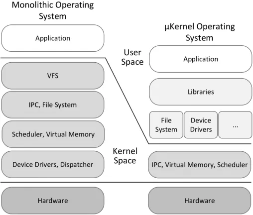
Operating systems follow essentially two different architectures: (i) monolithic and (ii) microkernel (also referred to as µkernel). The former executes all basic operating system services in kernel space, like the scheduler, interrupt controller, file system, etc. In this approach, numerous system calls are needed to allow applications to access all the services present in kernel space. The inclusion of all basic services in kernel space presents three big disadvantages: kernel size, extensibility as well as maintenance issues [13].
In this context, the µkernel was developed as a way to implement the most basic services in the kernel space, while everything else resides in user space (figure 2.1). Examples of operating systems following the aforementioned architectures are the GNU/Linux, monolithic-based and the QNX µkernel-based.
Application
VFS
IPC, File System
Scheduler, Virtual Memory
Hardware
Application
Libraries
File System
IPC, Virtual Memory, Scheduler
Hardware Device
Drivers ...
Device Drivers, Dispatcher
Monolithic Operating
System
µKernel Operating
System
Kernel
Space
User
Space
2.2.2
Real-Time Operating Systems
The word real-time in the embedded system context has a different meaning than the commonly used one. It’s used to describe an application or system that has to respond to an external stimuli in a finite amount of time. Furthermore, the purpose of these systems is not throughput, but the assurance that the stipulated deadlines will be met.
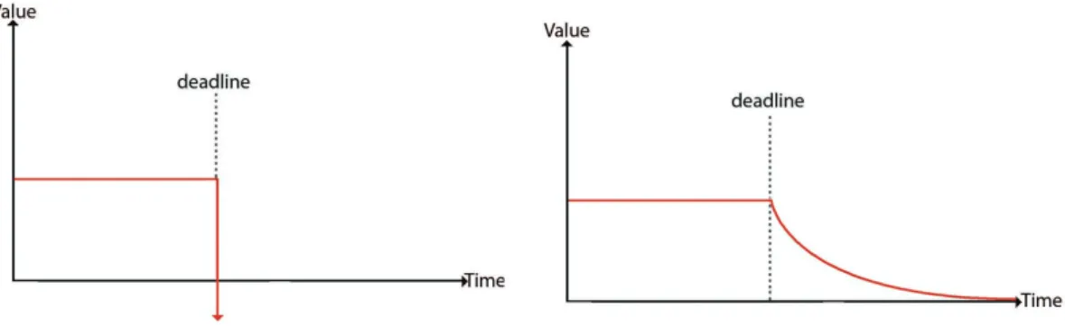
The degree at which an RTOS can tolerate missing deadlines and their associated consequences defines the type of RTOS: (i) soft real-time operating systems and (ii) hard real-time operating systems. In the former a deadline occasionally not being met is acceptable and doesn’t compromise the integrity of the system. However, for the latter the temporal deadline not being met is unacceptable and can cause permanent damage to the system. Figure 2.2 displays the value difference in soft and hard real-time operating systems when a deadline is not met. Given the real-time operating system prioritization of fast response times and determinism, complex scheduling algorithms are often implemented in order to achieve lower latency. Examples of such algorithms are: earliest deadline first (EDF), highest priority first (HPF) and rate-monotonic (RM).
Figure 2.2: Value of real-time systems in relation to deadlines not being met
Task Management
Real-time embedded systems need to be designed with the concept of multitasking in mind. Implementing an application generally requires splitting the work among several tasks, each responsible for a portion of the application’s work. This de-composition assists systems to meet performance and timing requirements. Task management involves the scheduling and context-switching of tasks within the
CPU (Central Processing Unit). In single-core solutions, this creates the illusion of having actual parallelism by maximizing the use of the CPU.
Scheduler
The scheduler is a key component of the kernel, responsible for ascertaining which task will be running next. How a scheduler decides processor time allocation has great impact on system performance, therefore scheduling algorithms have great importance. Most embedded real-time systems utilize priority-based scheduling, where each event is assigned a priority. When a new event arises, if its assigned priority is higher than the currently executing one, the currently executing task relinquishes CPU control over to the higher priority one.
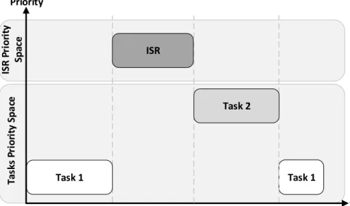
An example of the control flow in preemptive scheduling is presented in figure 2.3. In the beginning, only the lower priority task is executing and no task is waiting to start executing. An interrupt request happens and the kernel saves the context of the currently running task, and services the interrupt routine. When the interrupt service routine finishes its execution, the scheduler checks for the highest priority task waiting to execute and puts it running. At the end, when the high priority task finishes, the context of the low priority task is restored and resumes execution.
Task 1 Task 1 ISR P ri o ri ty Sp ac e Priority ISR Task 2 t Ta sk s Pr io ri ty Sp a ce
Context-switching
Context-switching is one of the main components of any multitasking system. The context-switching basically consists of changing the executing task on the processor core. This process consists of five steps [14]:
1. Start of context-switch - Context-switching is started, either by the currently executing task yielding processor control or an interrupt handler;
2. Save Context - Processor registers are saved into the Task Control Block (TCB) for the task being swapped out;
3. Scheduler decision - Decision regarding which task will run next;
4. Restore Context - Processor registers are stored for the task being swapped in;
5. Resume task execution - After the task content is restored, it resumes exe-cution.
Interrupt Management
An interrupt is an hardware mechanism provided to notify the CPU that an asyn-chronous event occurred. When an interrupt happens, the CPU saves the current task’s context and jumps to a special subroutine, an interrupt service routine. The ISR is then executed and upon completion, the program returns to either the interrupted task or the highest-priority task on the queue [14].
Within most applications are critical sections, defined as code segments that need to have run-to-completion semantics. When a task is running a critical section, and that critical section is accessible by other tasks or ISRs, this usually warrants the disabling of IRQs to protect it. In real-time systems the disabling of IRQs should be avoided as much as possible, since this leads to an increase in interrupt latency and the possibility interrupts being missed.
Time Management
Time management is crucial for operating systems. The knowledge of the passing of time is very useful for supporting temporal services provided to the applications.
Processors provide timers that generate periodic interrupts used by the operating system the implement temporal services.
Memory Management
Regarding real-time operating systems, multiple tasks can access the same memory space. As such, the operating system needs security mechanisms to protect task code, in order to maintain memory coherency [15]. One of the key services provided is the ability to manage tasks as independent programs, running them in their own private memory space, simplifying task design of individual tasks since they don’t need to know memory requirements of unrelated tasks. Furthermore, the kernel division into operating system’s distinction between kernel space and user space is accomplished by using hardware components, such as the Memory Management Unit (MMU), responsible for mapping virtual and physical memory, as well as controlling memory accesses.
To sum up, memory management is responsible for the following activities: (i) mapping physical and virtual memory, (ii) allocating and deallocating memory for system tasks, (iii) dynamic memory allocation, (iv) ensure cache coherency, (v) ensure memory protection and (vi) track memory usage of system components[16].
Synchronization
The need for synchronization mechanisms, stems from the necessity for kernels to keep track of shared resources to avoid data corruption and concurrency issues. On multitasking systems, locking resources on behalf of an executing task is essential for thread safety, by controlling access to shared resources. Regarding single-core systems, synchronization is contained to access control within the processor core and can be as simple as pinning the it to a specific task. Thus, no other task will have access to the shared resource. Real-time systems accomplish this by disabling processor interrupts upon task entry in critical sections.
Concerning multicore systems, implementing synchronism mechanisms the same way as single-core solutions would not suffice. Despite access from within the processor core being restricted, it provides no protection against access from tasks running on other cores. With the preceding concerns in mind, synchronization in multicore systems needs to be refined, by utilizing synchronization mechanisms in
a way that a task will only prevent others from executing if they require access to the same shared resource, regardless of the processor core they’re executing on. There are three main synchronization mechanisms:
• Built-in Atomicity. Some processor architectures provide, in their instruc-tion set, built-in operainstruc-tions that are indivisible (atomic) across all cores. Therefore, it can be used to implement synchronisation mechanisms.
• Semaphore. Sometimes referred as semaphore token, is a kernel object that one or more threads can acquire or release. Kernel keeps track of the number of times the semaphore was acquired or released. If a task requests the semaphore and no semaphore tokens are available, it has to block while waiting for the semaphore to become available.
• Mutual-Exclusion (Mutex). Special kind of semaphore that allows owner-ship, it possesses two states, locked or unlocked. After being acquired the mutex state changes to locked and no other task can lock or unlock the mu-tex, until its been release by the task that currently holds control over the mutex.
Messages Passing
Operating system tasks often need to communicate with each other: inter-task
communication. To accomplish this, tasks often use message queues. A message
queue works similarly to a pipeline, temporarily holding messages from the sender until the intended receiver is ready to read them, as presented in figure 2.4. Using this method, there is a decoupling of message sending and receiving, thus allowing tasks to only receive messages when they are ready to receive them.
Receive Send Send Msg Task 1 Msg Task 3 Task 1 Task 3 Task 2 Message Queue
2.2.3
Rate-Monotonic Priority Inversion
In real-time systems, interrupts are one of the biggest causes of priority inversion. This stems from the asynchronous nature of interrupts and the fact that they can preempt any task. If interrupts preempt an high-priority scheduled event, undesired behaviour can occur [17].
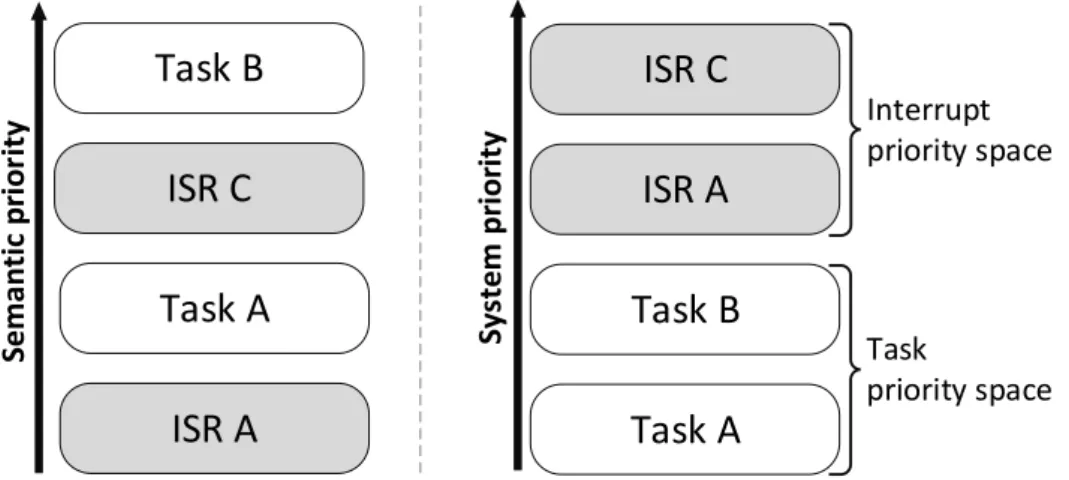
Event-triggered real-time systems have a bifid priority space, where essentially two priority spaces coexist: the hardware priority space, associated with inter-rupt management, and the software priority space, associated with task priority management. An example of such priority space is presented in figure 2.5. Funda-mentally, in real-time embedded systems featuring tasks and ISRs, high-priority software tasks can be interrupted by low-priority ISRs, inducing a well-known problem, termed rate-monotonic priority inversion. This causes loss in system scheduling precision and jitter in high-priority task execution, which can lead to missing temporal deadlines.
ISR C
ISR A
Task B
Task A
Interrupt priority space Task priority space Sy ste m p ri o ri tyISR C
ISR A
Task B
Task A
Sema n tic p ri o ri tyFigure 2.5: Bifid priority space example
2.3
Unified Priority Space Solutions
The previous section finished with an overview of the importance of priority and the problems of priority inversion in real-time systems. With the aforementioned priority space challenges in mind, this section presents a few solutions for priority space unification. Figure 2.6 displays the example of task priorities with an unified priority space.
ISR C Thread B Thread A ISR A Unified priority space Sy st em ’s p ri o ri ty
Figure 2.6: Unified priority space example
2.3.1
Interrupts as threads
Kleiman and Eykholt [18] present an approach that treats interrupts as asyn-chronously high-priority threads, implemented on the Solaris kernel for desktop and server systems. This concept allows interrupt handlers to use system ser-vices and introduces blocking semantics into the ISR abstraction. However, the introduced overhead to interrupt handlers makes them comparable to thread per-formance overheads, and still presents rate-monotonic priority inversion issues in certain scenarios.
2.3.2
Interrupt Synchronization in the CiAO
The CiAO is a project for aspect-aware operating systems, meaning it was devel-oped with the concept of configurability, exploiting aspect-oriented programming. Depending on the application, the programmer can configure a variant of CiAO for his particular requirements. The general idea behind this approach is if a re-source needs to be accessed by an IRQ handler that is currently being used by another IRQ handler or task, this requires the usage of interrupt synchronization. In this implementation interrupt service routines are split into two parts: prologue and epilogue. The former is devised for time-critical tasks that are restricted by shared resource access, and the latter can be requested by the prologue and has access to other components of the operating system, such as the scheduler. The main purpose of this division is to execute time-critical code immediately on an interrupt level and the rest later, when resources become available [19].
2.3.3
Customized hardware synthesized on FPGA or
sim-ilar
Several approaches rely on customized hardware using FPGAs, migrating oper-ating system functionalities to the hardware level. Although none these imple-mentations explicitly addresses the issue of rate-monotonic priority inversion, it is prevented as a side-effect of migrating of scheduler functions to hardware. Exam-ples of such approaches are: (i) HW-RTOS, that replaces the task synchronization and scheduler with a small hardware area[20] to increase system performance, (ii) Atalanta, implements a new multiprocessor RTOS making use of hardware/soft-ware codesign[21], (iii) Silicon TRON[22] and (iv) Task-Ahardware/soft-ware Interrupt Controller [23], which was designed with the idea of solving rate-monotonic priority inversion.
2.3.4
Sloth
Sloth introduces a more hardware-centric operating system by implementing all system tasks as interrupts, allowing the hardware interrupt subsystem to do most of the scheduling work. This approach allows an arbitrary distribution of priorities to tasks and interrupts, and the migration of scheduling decisions to hardware increases performance of system calls and context-switches [24]. Sloth tries to close the existing gap between operating system interface and the underlying hardware platform, adapting to the its peculiarities, instead of blindly abstracting from them [6]. Although this approach can be applicable to general-purpose operating systems, particularly suits special-purpose embedded systems, by solving rate-monotonic priority inversion issues. Furthermore, exploiting a more hardware-centric operating system is the key to achieve a higher degree of optimization. The Sloth concept in its pure form has some limitations that have been solved with the extension of the first work:
• Sleepy Sloth. With the standard sloth’s execution of threads as pure inter-rupts, threads can only use run-to-completion semantics, causing suboptimal CPU usage. This stems from the fact that, throughout its execution a thread may need to wait for externally generated signals and, instead of switching out the waiting task, the CPU has to stall until the signal arrives. Sleepy sloth presents an extension of Sloth by providing a way to overcome afore-said limitations, implementing a new thread abstraction that combines the
advantages of the Sloth concept with a blocking functionality [25].
• MultiSloth. With the ongoing trend of multicore systems spreading to the embedded systems, MultiSloth extends on the original work by expanding to multicore platforms. At the same time, maintaining the crucial charac-teristics of Sloth, resorting to advanced synchronization mechanisms in an efficient and deterministic fashion[11].
• Safer Sloth. A concern arises in sloth, due to the implementation of threads as interrupts. Each thread is mapped into an interrupt handler and, since interrupt handlers run in protected space, application code is also executing on protected space. Therefore, the sloth concept was criticized for being unsafe. As one of main focus of embedded systems is memory protection, the safer sloth was designed to maintain the main characteristics of Sloth, while tackling the problem of memory protection, by offering configurable degrees of protection between tasks [26].
2.4
Multicore
The backbone of any embedded system is the processor core, responsible for in-struction execution, reading encoded memory values that are mapped into instruc-tions. Single instructions are very primitive actions, but the combination of them can create very complex system behaviour. In single-core architectures, the pro-cessor can only execute instructions synchronously, relying on operating system software to run multiple tasks, by means of scheduling algorithms. The speed at which processors can execute instructions and, with the implementation of the aforementioned scheduling algorithms, the impression to the user is that multiple tasks are being executed concurrently. A problem with this approach is that the more tasks trying to get processor time for execution, the less overall time each task gets. Up until the early 2000s, this problem was masked by the continued increase of processor clock frequencies, to continually squeeze performance out of singlecore processors.
With the increase in the embedded system market, demand for faster systems has risen accordingly and singlecore architectures have struggled to match the market demand. Recently, microprocessor manufacturers have realized that continuously increasing clock frequency at the expense of power consumption was not a viable
solution, as power consumption reached unacceptable levels, specially in the em-bedded systems field. Mobile devices have been one of the emem-bedded systems that has grown more in the past few years. Nowadays, people often use their mobile device more than their personal computer. The increase in use of these devices, has made costumers grow to expect comparable performance and features from their mobile devices, while maintaining the expectancy for battery life the same as when mobile devices were in their early days. Multicore architectures emerge as the only viable solution to boost CPU performance with lower power consumption than their singlecore predecessors [27].
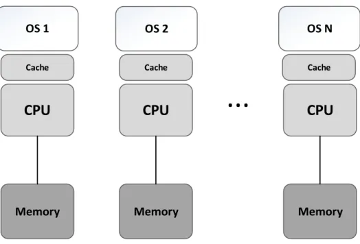
Multicore processors allow instructions to be executed asynchronously, each pro-cessor executes different tasks and, unlike singlecore systems, multicore systems can have true parallelism, thus increasing throughput. Another advantage of mul-ticore systems stems from the fact that they share peripherals and power supplies across all cores, providing a less expensive solution than having multiple singlecore systems. There are mainly two types of multicore architecture: Symmetric Mul-tiprocessing (SMP) and Asymmetric MulMul-tiprocessing (AMP). The difference be-tween them is significant yet fairly straightforward: while in SMP systems, all CPUs are connected to a shared memory space, using the same instance of the operating system, in AMP systems each CPU executes its own instance of the operating system, and each core has its own dedicated memory area.
2.4.1
Asymmetric Multiprocessing
Asymmetric multiprocessing configuration is defined by the existence of an inde-pendent instance of an operating system in each core, as presented in figure 2.7. AMP systems can have homogeneous or heterogeneous architecture: in the former each core runs the same type and version of OS, allowing applications running on one core to communicate with applications and services from other cores, in the latter each core runes either a different OS or a different version of the same OS and communication is a lot more complex.
Typically, a process and all its threads are locked to a single processor core. This is advantageous for running legacy code, but leads to a non-optimal processor core utilization. A process and its threads can be migrated from one core to another, albeit the time costs and complexity involved makes it very prohibiting and assumes even greater complexity, if the operating systems on both ends are
...
OS 1 OS 2 OS N
Cache Cache Cache
CPU
CPU
CPU
Memory Memory Memory
Figure 2.7: Asymmetric Multiprocessing Architecture different.
2.4.2
Symmetric Multiprocessing
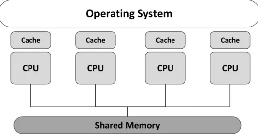
In a symmetric multiprocessing architecture all the processor cores are identical (homogeneous), employing a single operating system image, where all cores share a common memory area as well as IO devices, this is depicted in figure 2.8. In light of the symmetrical nature of system, all cores can execute code from memory, at the same time. A SMP operating system, must at all times, manage the scheduling of applications across all cores, this operation can be completely hidden from the running applications, where they have no control or knowledge of which task is running on which core at any given time. An application that is composed by several tasks that is able to run on a single core system, may very well be able to run in an SMP operating system. Nevertheless a re-structuring of the application is desirable to avoid concurrency issues and take full advantage of the SMP architecture [28]. The move to an SMP architecture does not warrant a need for the implementation of a new scheduler, what changes is the level of complexity within the scheduler. In single core architectures the scheduler has to manage several tasks within a core, on multicore it must do so across the several cores.
Operating System
Cache Cache Cache Cache
CPU
CPU
CPU
CPU
Shared Memory
Figure 2.8: Symmetric Multiprocessing Architecture
A few concerns must be taken into account when implementing an SMP operating system. First and foremost, synchronization issues that stem from the implemen-tation of a common memory area that is shared across all cores. Another point of concern of the SMP architecture is scalability, if too many cores attempt to access at the same point the same memory, causes a congestion in bus traffic and as such adding more cores will add little, or no performance increase to the system.
Chapter 3
System Specification
The previous chapter exposed the core concepts required for this dissertation. This chapter, in turn, presents an overview of the system, the key points of this chapter are presented, starting with the ARM architecture, its core concepts and the generic interrupt controller which is the backbone of the presented approach. After this, the FreeRTOS operating system will be analysed, presenting an archi-tectural overview of the system, and describing how the scheduling system and the synchronization mechanisms work. To finalize the chapter an overview of the the development environment is presented: the Xilinx toolchain, ARM Fast Models and its Versatile Express model.
3.1
ARM Architecture
The key attributes of low power consumption, small size and high performance, altogether with an architectural simplicity made ARM processors very popular among embedded devices. The ARM architecture follows the Reduced
Instruc-tion Set Computer (RISC) architecture, incorporating its basic features as well
as adding its own improvements allowing a good balance between performance, power consumption and silicon area. There have been seven major versions of the ARM architecture. The ARMv7 architecture, utilized in this dissertation, is split into three profiles: (i) ARMv7-A, (ii) ARMv7-R and (iii) ARMv7-M [29].
i. The ARMv7-A is application focused, running complete operating systems, characterized by high performance demand from its applications. These
processors target smartphones, tablets and infotainment systems.
ii. The ARMv7-R has a real-time profile, being these processors used for criti-cal systems where reliability and predictability are decisive. These processors can be found in hard-drives, networking equipments and in critical systems like cars ABS (anti-lock braking system).
iii. The ARMv7-M targets microcontrollers which needs little processing power but a large amount of input and output lines and deterministic behaviour. Processors with this profile are extensively present in bluetooth devices, touchscreen controllers and remote control devices.
3.1.1
Processor Fundamentals
The ARM Cortex-A9 was designed as an high-performance and low-power pro-cessor implemented under the ARMv7-A architecture. These propro-cessors can be implemented in both uniprocessor and multiprocessor configurations, where multi-processor configurations are provided in a cache-coherent cluster, utilizing a Snoop Control Unit (SCU). These processors provide also a set of private memory-mapped peripherals, including a global timer, watchdog and private timers for each present processor core. For the interrupt management, an integrated interrupt controller - the Generic Interrupt Controller - is available (see subsection 3.1.2).
The following features are included within the Cortex-A9 processor: • ARM, Thumb and ThumbEE instruction set support;
• Security Extensions technology, commonly referred to as TrustZone technol-ogy;
• Advanced SIMD architecture extension to accelerate the performance of mul-timedia applications, for instance, 3D graphics and image processing; • Vector Floating-Point v3, for floating-point computation (compliant with the
IEEE 754 standard);
Processor Modes
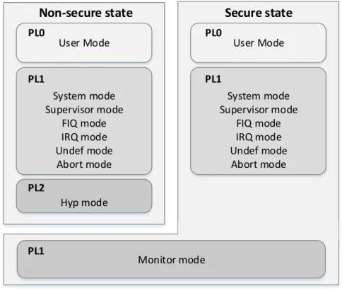
The Cortex-A9 processor provides several processor modes and privilege levels defined by the ARM architecture [29], and depicted in figure 3.1:
i. User mode - This mode restricts use of the system resources (unprivileged execution - PL0) and so this is the mode where usually operating systems run their applications. Programs than run in user mode cannot access protected system resources, can only make unprivileged access to memory and cannot change mode, except by initiating an SVC or by external events (interrupts for instance).
ii. System mode - Software running in System mode (executes at PL1), has the same registers available as User mode, however having an higher level of privilege and having the possibility to access some registers not available at user mode.
iii. Supervisor mode - Upon a Supervisor Call (SVC) this is the default mode the exception goes to. Furthermore at the processor reset, the processor enters in supervisor mode.
iv. Abort mode - The default mode that a Data Abort exception or Prefetch abort takes, meaning the processor could not access the required memory location or a failed attempt to fetch a instruction.
v. Undefined mode - Instruction related, when an undefined instruction is taken. Usually this happens when the core is looking for instructions in the wrong place (corrupted Program Counter), or if the memory itself is corrupted. Can also occur on coprocessor faults;
vi. FIQ mode - Default mode taken when an FIQ occurs, in this mode regis-ters R8 to R12 are banked, reducing the need to save register contents and minimizing the overhead of context switching;
vii. IRQ mode - Default mode taken when an IRQ occurs;
viii. Hyp mode - Non-secure PL2 mode, part of the Virtualization Extensions. Normally used by a hypervisor, that controls and switches between Guest OSs that execute at PL1.
is taken. This is a Secure mode, software running in this mode has access to both Secure and Non-Secure copies of system registers (only available if the implementation includes Security Extensions).
User Mode System mode Supervisor mode FIQ mode IRQ mode Undef mode Abort mode Hyp mode
Non-secure state
PL0 PL1 PL2 Monitor mode PL1 User Mode System mode Supervisor mode FIQ mode IRQ mode Undef mode Abort mode PL0 PL1Secure state
Figure 3.1: Overview of processor modes and privilege levels with security and virtualization extensions
Atomicity in the ARM Architecture
The ARM architecture provides dedicated instructions to perform atomic accesses to memory. The synchronization primitive instructions are defined as the instruc-tions executed to ensure memory synchronization:
• LDREX, STREX - Load and Store Register Exclusive;
• LDREXB, STREXB - Load and Store Register Exclusive Byte; • LDREXD STREXD- Load and Store Register Exclusive Doubleword; • LDREXH STREXH- Load and Store Register Exclusive Halfword;
These instructions must be used in pairs, which means that a Load-Exclusive instructions must be used only with the corresponding Store-Exclusive.
Exceptions and Interrupts
An exception in the ARM architecture motivates the processor to suspend pro-gram execution to handle an event, entering an execution mode at PL1 or PL2, as well as the execution of a software handler for the corresponding exception. These exceptions can be: (i) reset, (ii) interrupts, (iii) memory system aborts, (iv) undefined instructions and (v) Supervisor (SVCs), Secure Monitor (SMCs) or Hypervisor calls (HVCs).
Upon the occurrence of an exception, the processor execution is forced to branch to the address which corresponds to the type of exception being handled (exception vector). The set of exception vectors for all exceptions is called exception vector table [29].
3.1.2
Generic Interrupt Controller
The previous subsection ended with an overview of the Cortex-A9 exception and interrupt handling. The present subsection presents an overview of the ARM Generic Interrupt Controller (GIC). The GIC’s overview begins with an archi-tectural overview of the interrupt controller, followed by the different types of interrupt sources and how the GIC does the interrupt handling and prioritization. Concluding the GIC overview with an explanation of the optional GIC Security Extensions and the limitations of the GIC version utilized in this dissertation, that shares the same programmers model as the PrimaCell Generic Interrupt Controller (PL390), with some implementation-specific differences [30, 31].
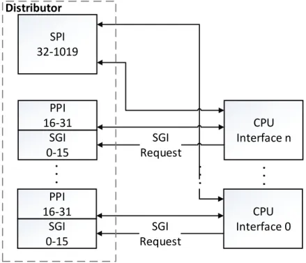
The GIC architecture is split into two logical blocks, a Distributor block and one or more CPU interfaces.
Distributor
The Distributor block is the first interface for every interrupt, it centralizes all interrupt sources and stores all their properties. The distributor is also responsi-ble for dispatching the interrupt with the highest priority to the interface
corre-sponding target CPU. The programmable options provided by the CPU interface block are: (i) enabling and forwarding of interrupts to the CPU interfaces; (ii) enabling and disabling interrupts individually; (iii) setting a priority level for each interrupt; (iv) setting the interrupt target processor; (v) setting each interrupt as level-sensitive or edge-triggered; (vi) if security extensions are implemented, also provides a way to set each interrupt as Secure or Non-secure; (vii) sending software generated interrupts, SGI, to one or more target processors.
CPU Interface
The CPU Interface block provides a CPU interface for each processor, where each interface is responsible for performing priority masking and preemption handling for its connected processor. The programmable options provided by the CPU interface block are:(i) enabling the signalling of interrupts to the processor; (ii) interrupt acknowledgement; (iii) interrupt process completion indication; (iv) in-terrupt masking; (v) definition of preemption policies; (vi) determining the highest priority pending interrupt to be signalled to the processor.
Interrupt Sources
The GIC provides several types of interrupt sources:
• Software Generated Interrupts(0-15) - SGIs are interrupts generated by software, using the GICD_SGIR register in the Distributor and can be used for interprocessor communication. If the system implements Security Extensions interrupt 0 to interrupt 7 are used for Non-secure interrupts and interrupts 8 to 15 are used for secure interrupts.
• Private Peripheral Interrupts (16-31) - PPIs are peripheral interrupts that are specific to a single processor, so they are banked for every proces-sor. These interrupts can be triggered by hardware or by writing to the GICD_ISPENDxregister in the Distributor;
• Shared Peripheral Interrupts (32-1019) - SPIs are peripheral interrupts that the Distributor can route to any combination of processors. These interrupts can be triggered by hardware or by writing to the GICD_ISPENDx register in the Distributor;
• Reserved (1020-1021);
• Interrupt Grouping (1022) - This interrupt is only used if the GIC sup-ports priority grouping. Indicates that there is a Group 1 interrupt of suffi-cient priority to be signalled to the processor that must be acknowledged; • Spurious Interrupt (1023) - This interrupt is used when an interrupt that
was signalled by the GIC to the processor is no longer required. When the processor acknowledges the interrupt, the GIC returns a special interrupt ID, identifying it as a spurious interrupt.
Figure 3.2 presents an overview of the GIC, showing its architectural division into Distributor and CPU Interfaces, as well as the division between types of interrupts and their connection with each associated interface.
SGI 0-15 PPI 16-31 CPU Interface 0 SPI 32-1019 SGI Request SGI 0-15 PPI 16-31 CPU Interface n SGI Request
. .
.
. .
.
. .
.
DistributorFigure 3.2: GIC Architectural Overview
Interrupt Handling and Configurations
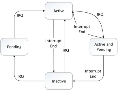
The GIC provides four states for each interrupt: (i) inactive; (ii) pending; (iii) active; (iv) active and pending. The conditions that allow a switch in the state of each interrupt to occur are referenced in figure 3.3.
IRQ Interrupt End IRQ Interrupt End Active Active and Pending Pending Inactive IRQ IRQ Interrupt End
Figure 3.3: GIC Interrupt States
When an interrupt request takes place the GIC checks if the interrupt is enabled and sets it as pending. The Distributor determines the highest priority pending interrupt for every processor and forwards that interrupt for each CPU interface. The CPU interface, in turn, compares the value of the highest pending interrupt with the priority mask, and if the pending interrupt has higher priority than the priority mask value, so the CPU interface signals an interrupt exception request to the processor, as depicted in figure 3.4.
The GIC provides several programmable settings for interrupt control.
i. Allows enabling and disabling of interrupts through the GICD_ISENABLERx and GICD_ICENABLERx registers respectively;
ii. Allows setting and clearing the pending state of an interrupt using the GICD_ISPENDRxand GICD_ICPENDRxregisters, respectively;
iii. Allows setting the interrupt priority using the GICD_IPRIORITYRx registers; iv. Allows setting the target of each SPI using the GICD_ITARGETSRxregisters; v. Allows setting the interrupt as level-sensitive or edge-triggered using the
IRQ
Determine highest priority pending interrupt for CPU 0
Determine highest priority pending interrupt for CPU N
. . . Highest pending > Priority Mask Highest pending > Priority Mask CPU Interface 0 CPU Interface N Distributor
Core 0
Core N
Interrupt set as pending . . . . . .Figure 3.4: GIC Interrupt Handling GIC Security Extensions
Security Extensions are available in the ARMv7-A architecture, and this feature facilitates the integration of hardware security mechanisms, providing Secure and Non-secure virtual memory space.
The Security Extensions implement a division of interrupts into Secure (Group 0) and Non-secure (Group 1). The behaviour of processor accesses to registers is dependent on the group associated with the interrupt. Secure accesses can read or write information regarding both Secure and Non-secure interrupts, while Non-secure accesses can only read or write information belonging to Non-secure interrupts.
Limitations
The version of the GIC present in both development platforms (see section 3.3) displays a few limitations: (i) most PPIs are reserved, only 27 through 31 are available and destined for the Global Timer, legacy nFIQ pin, Private Timers and legacy nIRQ pin respectively; (ii) the number of SPIs is limited to 64 (iii) The number of priority levels available for interrupts, the FreeRTOS provides 255
priority levels, and so the GIC should match that to provide equal number of different task priority, which is not the case since it provides less than 8 priority assignment bits.
3.2
FreeRTOS
The FreeRTOS is a real-time operating system, written mainly in the C program-ming language. As the name suggests the FreeRTOS is an open source, fully supported and is in constant development. First introduced by Richard Barry in 2002, it is one of the most used real-time operating systems, and has been ported to 35 architectures [5].
3.2.1
Introduction and architectural overview
The FreeRTOS presents a simple, yet very clever architectural division into two lay-ers: hardware independent and portable (hardware dependent) layer. The former is responsible for most operating system functions, and the latter for hardware-specific processing (context-switching for instance), for this reason, the hardware independent layer remains unaltered across all ported versions. The aforemen-tioned layered division is also apparent in the operating system’s source files, as presented in figure 3.5. Not all source files are mandatory, for example, the croutine.c, queue.c and timers.c are optional files in the operating system, whereas all others are mandatory.
port.c heap.c list.c
task.c Hardware
Independent Layer Portable Layer Required
croutine.c queue.c timers.c
Optional
3.2.2
Tasks and Scheduling
The FreeRTOS supports fixed-priority preemptive and cooperative scheduling. In order to implement the scheduling system and related services, the FreeRTOS provides several doubly linked lists, one for each state and a few more for task management purposes (e.g., task deletion). At the core of the FreeRTOS scheduler are ready-state linked lists, where for each priority there is a corresponding linked list, that contains each task ready-to-run that has that priority. The scheduler determines the highest priority ready to be scheduled by running through the items at the head of the non-empty highest priority ready list.
Task Control Block
The Task Control Block (TCB) is the data structure that contains the task infor-mation and is used by the scheduler to identify it in queues, and retrieve and store pertinent information about the task. The FreeRTOS provides a pointer to identify the location of the TCB of the current task in execution, named pxCurrentTCB, as displayed in figure 3.6. pxTopOfStack xGenericListItem uxPriority pcTaskName ... tskTCB pxCurrentTCB
1
1
Figure 3.6: Task Control Block
Task Creation
A task is created using thexTaskGenericCreate() function. This entails the allo-cation of the task’s memory, the memory belonging to the task’s stack (which size is user specified in the function call) and the task control block. After the stack
is allocated, it is prepared so it can be started by the context-switching code, and at the end the task is added to the ready queue waiting to be scheduled.
Task States
Tasks running on the FreeRTOS can switch between several states, as shown in figure 3.7. The first distinction between task states is a fairly generic one, running or not-running. This distinction is not enough to fulfil all the requirements of the operating system, and so the not-running state is expanded into three different states: (i) ready, (ii) suspended and (iii) blocked.
i. Ready - which means a task is ready and can scheduled at any time;
ii. Suspended - the task was suspended by the user and is waiting for a resume to enter the ready state;
iii. Blocked - the task was blocked waiting on an event to enter the ready state. iv. Running - state which a task takes when is currently in execution;
Suspended Ready Blocked Running Resume Suspend Event vTaskSuspend() Blocking API vTaskSuspend() Not Running