Universidade de Aveiro Departamento de Eletrónica,Telecomunicações e Informática
2020
Diogo
Duarte
Comparação de Ferramentas de Desenvolvimento de
Linux Embutido
Universidade de Aveiro Departamento de Eletrónica,Telecomunicações e Informática
2020
Diogo
Duarte
Comparação de Ferramentas de Desenvolvimento de
Linux Embutido
Comparison of Embedded Linux Development Tools
Dissertação apresentada à Universidade de Aveiro para cumprimento dos requisi-tos necessários à obtenção do grau de Mestre em Engenharia de Computadores e Telemática, realizada sob a orientação científica do Doutor João Manuel de Oliveira e Silva Rodrigues, Professor auxiliar do Departamento de Eletrónica, Tele-comunicações e Informática da Universidade de Aveiro, e coorientação empresarial do Mestre Sérgio Paulo Santos Silva, Diretor Técnico da empresa Globaltronic
-o júri / the jury
presidente / president Prof. Doutor Tomás António Mendes Oliveira e Silva
professor associado da Universidade de Aveiro
vogais / examiners committee Prof. Doutor António Manuel de Jesus Pereira
professor coordenador c/ agregação do Instituto Politénico de Leiria
agradecimentos /
acknowledgements Sem dúvida de que todas as pessoas que conheci e com quem interagi contribuiramde alguma forma para a maneira com que eu cheguei a esta etapa da minha vida, e em consequência, a este trabalho. Contudo, gostava de dirigir umas palavras dire-tas de agradecimento às pessoas que contribuiram mais de perto para este projeto. Ao meu professor e orientador João Rodrigues, pela exelente orientação e paciência, mesmo quando ia perdendo o focus com projetos paralelos. Ao meu co-orientador empresarial Sérgio Silva, antes de mais pela oportunidade de poder desenvolver este projeto tão de perto na empresa, assim como pelo suporte e ajuda mesmo para coisas fora do projeto em si. Ao Salviano Soares, pela disponibilidade para me ajudar sempre que precisei e pela motivação para completar esta dissertação. Ao colaborador da Globaltronic Fábio Silva, o developer de Linux embutido da Glob-altronic, pela ajuda e disponibilidade para explicar as dúvidas que tive sobre esta e outras áreas de interesse. A todos os outros colaboradores da Globaltronic, pelas trocas de ideias e disponibilidade para me ensinarem. E por fim, mas sem dúvida não menos importante, à minha família e amigos mais próximos pela compreensão
Palavras Chave linux embutidos, sistemas operativos, Armbian, Yocto.
Resumo O crescente interesse na ligação de pequenos sensores à internet levou ao apa-recimento de sistemas operacionais capazes de operar em qualquer hardware as-segurando todas as funcionalidades de rede, interface gráfica, servidor, etc. A Globaltronic, uma empresa sedeada em Águeda, tem vindo a desenvolver a plata-forma de hardware WiiPiiDo, que se caracteriza por ser um computador embebido altamente especializado para IoT e capaz de assegurar a ligação às redes NB-IoT-LTE Cat NB1 (Narrow Band IoT), permitindo o rápido desenvolvimento de solu-ções IoT completas para os utilizadores. Por tudo isto, é indispensável criar uma imagem Linux que garanta a fácil utilização de todas as potencialidades da pla-taforma de hardware. Neste contexto, analisamos o Projecto Yocto, que oferece um sistema de desenvolvimento composto por diversas ferramentas para criação de distribuições Linux para sistemas embutidos, e que tem ganho popularidade numa grande comunidade de utilizadores, especialmente empresas. Contudo, o Yocto não é a única escolha da comunindade de desenvolvedores de sistemas embuti-dos. De facto, o Armbian, que é uma distribuição baseada em Debian/Ubuntu especializada para sistemas ARM, aparece como uma escolha popular para o de-senvolvimento de imagens nestes ambientes. Neste trabalho, iremos ver os passos necessários para testar a plataforma de hardware WiiPiiDo, desde o primeiro ar-ranque até ao desenvolvimento do sistema operativo de suporte, não esquecendo o desenvolvimento dos drivers de suporte aos dispositivos integrados e os testes de desempenho. No final, as ferramentas de desenvolvimento para a criação das ima-gens vão ser comparadas, desde os resultados obtidos nos testes de performance,
Keywords embedded linux, operating systems, Armbian, Yocto.
Abstract The increasing interest to connect small sensors to the internet took the develop-ment of operating systems able to operate in any hardware ensuring all network, graphical and server functionalities. Globaltronic, a company in Águeda, has de-veloped a hardware platform call WiiPiiDo, that can be described as a embedded computer, power by an ARM SoC, highly specialized for IoT, ensuring connection to the Internet even in harsh conditions using NB-IoT- LTE Cat NB1 (Narrow Band IoT), does ensuring rapid development of complete IoT solutions for end-users. The development of a Linux image that exposes all the potential of the hardware platform is a must and will provide extra value to it. In this context, we take a look at the Yocto Project, which is a building environment that allows the creation of such a operating system, and that is gaining a crescent community of users and specially enterprises. Nevertheless, Yocto is not the only choice for the developer community for embedded platforms, in fact, a distribution like Armbian, a Debian/Ubuntu based Distribution that is specialized for ARM boards, appears as a popular alternative for embedded development in ARM development boards. In this work we will see the steps necessary to test the first boot of the hard-ware platform until the development of the supporting operating system, passing through the driver development and performance tests. In the end, the used build system will be compared, from the results of the tests performance, to the build
Contents
Contents i
List of Figures iii
List of Tables v
Glossary vii
1 Introduction 1
1.1 The WiiPiiDo board . . . 3
1.2 Purpose and goals . . . 5
1.3 Thesis structure . . . 5
2 Linux Development Tools 7 2.1 Bootloader . . . 7
2.2 Kernel . . . 8
2.3 Device tree . . . 8
2.4 Device drivers . . . 9
2.5 Tools for developing a Linux image . . . 9
2.5.1 The BuildRoot development tool . . . 10
2.5.2 The Yocto Project . . . 10
2.5.3 The Armbian build system . . . 10
2.5.4 ELBE . . . 11
2.5.5 OpenWrt . . . 11
2.6 Comparison of development tools . . . 11
2.7 Synthesis . . . 14
3 Image Prototyping and Peripherals Integration 15 3.1 Bootloader validation . . . 16
3.1.1 Compiling the Bootloader . . . 16
3.1.3 Booting . . . 18
3.1.4 Boot using FEL . . . 20
3.2 Creating a minimal Linux image . . . 20
3.2.1 Building the image . . . 21
3.2.2 Configuration menu . . . 21
3.2.3 Booting . . . 23
3.3 Peripherals integration . . . 24
3.3.1 Example: GPIO port . . . 25
3.4 Synthesis . . . 25
4 Building The Final Images 27 4.1 Building an image in Armbian . . . 27
4.1.1 Building a test image . . . 28
4.1.2 Adding support for the WiiPiiDo . . . 29
4.2 Building an image in Yocto . . . 31
4.2.1 Building a test Image . . . 33
4.2.2 Adding support for WiiPiiDo . . . 35
4.3 Synthesis . . . 37
5 Testing Results 39 5.1 Automatic peripherals validation . . . 39
5.1.1 Procedure . . . 40 5.1.2 Test examples . . . 40 5.1.3 Results . . . 42 5.2 Field test . . . 43 5.2.1 Procedure . . . 43 5.2.2 Results . . . 44 5.3 Synthesis . . . 46 6 Conclusions 49 6.1 Conclusions . . . 49 6.2 Contributions . . . 50 6.3 Future Work . . . 50 A Source Files 53 Referências 59 ii
List of Figures
1.1 OS used in Internet of Things (IoT) devices . . . 1
1.2 Linux Distribution preference [4] . . . 2
1.3 The WiiPiiDo Board Components [8]. . . 5
3.1 The Universal Boot Loader (U-Boot) Missing BL31 Warning . . . 17
3.2 U-Boot Menuconfig Home . . . 18
3.3 WiiPiiDo to PC Serial Connection . . . 19
3.4 U-Boot First Boot . . . 19
3.5 BuildRoot menuconfig Home . . . 22
3.6 BuildRoot output images . . . 23
3.7 Device Validation Approach . . . 24
3.8 Missing GPIO sysfs interface. The /sys/class/gpio directory is absent. . . 25
4.1 Armbian Folder Structure . . . 27
4.2 Armbian Compilation . . . 29
4.3 Armbian Source Files Patch . . . 30
4.4 Poky Repository Structure . . . 31
4.5 Yocto Board Support Package (BSP) Layer Structure . . . 32
4.6 Armbian Build Process . . . 37
4.7 Yocto Build Process . . . 38
5.1 WiiPiiDo Test Utility (WTU) Output . . . 40
5.2 1-Wire Test jig Schematic . . . 41
5.3 Universal Serial Bus (USB)-Universal Asynchronous Receiver-Transmitter (UART) Bridge Test jig Schematic . . . 42
5.4 Field test setup . . . 44
5.5 Memory usage from boards P1, P2 and P3 . . . 45
5.6 CPU usage . . . 46
List of Tables
1.1 Single Board Computers (SBCs) Comparison . . . 4
2.1 Build Environment Differences . . . 13
5.1 Manual Test Results . . . 42
5.2 WTU Results . . . 43
5.3 Test Equipment . . . 44
Glossary
ADC Analog-to-Digital Converter
ARM Advanced RISC Machine
BIOS Basic Input/Output System
BL31 Boot Loader Stage 3-1
BSP Board Support Package
CLI Command Line Interface
CPU Central Processing Unit
DTB Device Tree Blob
dtc Device Tree Compiler
DTS Device Tree Source
eMMC Embedded MultiMediaCard
GPIO General-Purpose Input/Output
GPS Global Positioning System
HDMI High-Definition Multimedia Interface
IoT Internet of Things
MBR Master Boot Record
NB-IoT Narrow Band IoT
OOP Object Oriented Programming
OS Operating System
OTG On-The-Go
PCB Printed Circuit Board
PWM Pulse-width Modulation
RAM Random-Access Memory
RF Radio Frequency
ROM Read-Only Memory
RTCC Real Time Clock and Calendar
SBC Single Board Computer
SoC System on a Chip
SPI Serial Peripheral Interface
SPL Second Program Loader
TUI Terminal User Interface
UART Universal Asynchronous Receiver-Transmitter
U-Boot The Universal Boot Loader
UEFI Unified Extensible Firmware Interface
USB Universal Serial Bus
CHAPTER
1
Introduction
This chapter will give the introduction and explain the purpose and goals, as well as thestructure of the whole thesis.
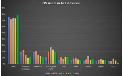
The emergence of IoT devices in the development industry brings new challenges to the design perspective. According to Fortune Business Insights report of 2019, the Global IoT Market was valued at 172 Billion Euros in 2018 and is expected to reach the 1000 Billion Euros by 2026 [1]. The IoT is a multidisciplinary paradigm in which many of the objects that surround us will be networked and connected to the Internet in order to provide new and more efficient services [2]. The diversity of IoT applications and technologies makes it difficult to present a general comprehensive statement for the requirements of IoT in hardware and software [3]. According to the Eclipse IoT Working Group surveys [4], for five years in a row Linux is the most used Operating System (OS) for embedded IoT devices, followed by Windows Embedded and FreeRTOS. Figure 1.1 summarizes the results obtained in the IoT Developer Surveys since 2015.
In the 2019 survey, the Linux results are further divided into several distributions. Figure 1.2, from the 2019 survey, shows that Debian and its derivatives like Raspbian and Ubuntu dominate the developer’s preferences, followed by CentOS and Yocto.
Figure 1.2: Linux Distribution preference [4]
The fast development of new architectures and platforms specially design to face the challenges of IoT and the developers preference in the risen of new IoT products gathering data, tracking usage, monitoring functionalities, automating systems and processes all over the world. Therefore, companies all over the world are investing in this new market by developing new platforms from fully embedded devices to SBC. This huge market is expected to reach 1.5 trillion Euros in 2020, and, according to Coldwell Banker study [5] more than a quarter of all consumers already own a smart-home device, i.e., a device that is connected and allows the automation of functions that once had to be controlled manually. It is, nevertheless, important to clarify the difference between an embedded system and a general purpose computer, since all of these are computational networked devices, but with different purposes.
An embedded system can be defined as a computer hardware system with integrated software that is designed for a specific task, or a small set of specific tasks [6]. Embedded systems are integrated in many devices nowadays, such as smartphones, routers, building tools, house appliances, cars, IoT devices, and many others. Since they have small sets of tasks to perform, embedded systems can be designed to minimize the size, the cost and power consumption, and to improve the performance and reliability of the system. This contrasts with personal computers, which are general-purpose devices, being used to perform a multitude of tasks, such as web browsing, gaming, video editing, etc. An embedded system is characterized by [7]:
• Having a single, or small set of tasks to perform
• Being optimized in terms of size, cost, performance, etc, only to provide the necessary requirements for the tasks to perform
• Often having to operate under real time constraints • Being able to react to changes
1.1 The WiiPiiDo board
Capitalizing on the evolution of the market from purely embedded systems to SBCs, Global-tronic1, a company based in Águeda (Aveiro, Portugal) that is specialized in the development of integrated electronics with hardware, firmware, software and prototyping, developed the WiiPiiDo board. This is the target board for the images that were developed in this thesis.
The core components of the board are listed below, with references to Figure 1.3. • Quad-Core ARM Cortex A53 64-bit System on a Chip (SoC) 18
• 8GB iNAND Embedded MultiMediaCard (eMMC) flash memory 15
• 2GB DDR3 Random-Access Memory (RAM) 17
• Wi-Fi and Bluetooth 4.0 23
• U-Blox Max M8Q, Global Positioning System (GPS) 22
• Quectel BC66, Narrow Band IoT (NB-IoT) 20
• 4K/30Hz HDMI 6
• 1 Real Time Clock and Calendar (RTCC) 15
• 3 Differential Analog-to-Digital Converters (ADCs) • Raspberry Compatible GPIO Header 11
• 40 Additional General-Purpose Input/Output (GPIO) Ports 12, 13
• 1 MicroSD Card Slot 8
• 4 USB Ports 2 , 3
• 1 USB-On-The-Go (OTG) Port 4
• Gigabit LAN 1
• Audio Jack Connector 5
• MIPI Display 7
Table 1.1 shows the comparison of the main features between the WiiPiiDo board, and 3 other popular SBCs on the market, the Raspberry Pi 4 Model B2, the BeagleBone Black3 and the Pine A64+4.
From this table, we can highlight some the main advantages that the WiiPiiDo board has against the other boards as the internal storage, NB-IoT, ADCs and RTCC, as well as other non-component related features such as having an high working temperature threshold, from -20 to 70 ºC. This way, this board is more recommended for industrial applications, instead of
home use, having more communication options than most other SBCs.
1Globaltronic Portugal –https://www.globaltronic.pt/en/ 2
Raspberry Pi 4 Model B –https://www.raspberrypi.org/products/raspberry-pi-4-model-b/
3BeagleBone Black –https://beagleboard.org/black/ 4
WiiPiiDo Raspb erry Pi 4B BeagleBone Blac k Pine A64+ SoC Allwinner A64, 1.2GHz 4-Core Broadcom BCM2711, 1.5 GHz 4-Core TI AM3359AZCZ100, 1GHz Allwinner A64, 1.2GHz 4-Core RAM 2 GB DDR3 1,2,4 GB DDR4 512 MB DDR3 1,2 GB Flash 4 GB – 4 GB – Ethernet Y es, Gigabit Y es, Gigabit Y es, 10/100M Y es, Gigabit Wi-Fi Y es 802.11 a/b/g/n single-band Y es 802.11 b/g/n/ac dual-band – – NB-IoT Y es – – – Blueto oth Y es 4.0 Y es 5.0 – – R TCC Y es – – – ADC Y es – – – GPS Y es – – – T able 1.1: SBCs Comparison 4
Figure 1.3: The WiiPiiDo Board Components [8].
1.2 Purpose and goals
The purpose of this work was to study and compare multiple embedded Linux building environments, highlighting their main differences and characteristics. With this research we selected the most appropriate environments to be used to generate Linux images that fully support the WiiPiiDo board. The chosen environments were selected to be versatile and allow easy maintainability by the manufacturer, but also to be able to accommodate multiple client profiles.
1.3 Thesis structure
In Chapter 1 the motivations for the development of this thesis are presented, as well as its objectives. Chapter 2 starts with a description of the Linux subsystems and functionality that generally require customization for deployment on an embedded system. Then, several currently existing tools for developing Linux distributions for embedded systems are presented and compared. In Chapter 3 we present an initial development of test images that were developed to do a quick first validation of the first prototypes of the WiiPiiDo board. In the last sections of this chapter, we also demonstrate the implementation of device drivers in the board. In Chapter 4 we describe the implementation of two embedded Linux images developed using the Armbian and Yocto building environments, respectively. In Chapter 5 the built images are evaluated. In a first scenario, the different components from the board are validated in the different built images, using a test utility developed for this purpose. In
a second scenario, the memory usage, CPU performance, as well as some internal metrics are evaluated and compared between different images and boards. Finally, in Chapter 6, the results of this thesis are summarized, and some of the possible future work is discussed.
CHAPTER
2
Linux Development Tools
This chapter is intended to situate the reader in the context of the project, giving brief notions of the basic information needed for the rest of the thesis, as well as present some building environments that were studied.In the development that will be done further down the line, the changes that will be done to the configurations to be able to support the new board will be focused in the following:
• Bootloader • Kernel
• Device Tree Source (DTS) • Device Drivers
2.1 Bootloader
After a device is powered, the first process to run is the boot sequence. In a common desktop computer, this process is divided in multiple parts [9]:
The Hardware Boot The Hardware Boot consists of running a program directly from Read-Only Memory (ROM), the Basic Input/Output System (BIOS) or Unified Extensible Firmware Interface (UEFI) depending on the machine, that will do some basic self-testing and read further parameters from non-volatile memory. One of these parameters will then tell the computer where the boot device is located, and load the OS loader from a fixed address in this device.
The OS loader At this stage of the boot sequence, the computer is trying to find the kernel in a device and load it. In computers, this loader is located in the first sector of the boot device, the Master Boot Record (MBR). Due to limitation in size and complexity of the bootloader, this process is usually divided in two parts:
1. The First stage loader, which is initialized in the MBR
2. The Second stage loader, that is located in a device with a larger capacity, and contains the full featured loader
In Linux, the most typical OS loader are LILO and GRUB.
The Kernel Initilization It is at this point in the boot sequence that the multiple compo-nents that exist in the computer are initialized.
Other At this stage, there are a couple more steps the root user-space process and the boot script, respectively. But as these are not important in this description, they will not be presented further.
In embedded Linux, a similar boot sequence is performed, however, instead of separating the first two steps in multiple programs, only a single program will perform those tasks [10]. This program is the bootloader, and most devices use U-Boot. U-Boot is an open source bootloader that can be built to work on a multitude of architectures, being popular in embedded Linux devices.
2.2 Kernel
The Kernel is a program that is loaded to RAM at the boot sequence, that contain critical functions required for the OS to work correctly [11, Chapter 1.4]. This functions consist in managing system resources, such as RAM, and processor time, as well as to manage and interact with hardware components.
2.3 Device tree
When working with desktop and server computers, as they are widely used, the firmware interfaces for this machines are standardized to make it easier for OS developers to integrate hardware their OS. This however does not happen in embedded systems and embedded Linux. As systems vary widely, and software and firmware is customized for each SBC, there is no pressure in the market to standardized the firmware interfaces [12]. This way, to make this easier on SBC, we make use of Device Trees in embedded Linux.
The Device Tree is a software data structure that is used to describe and configure the hardware in a system, allowing the kernel to remain the same, by separating hardware specific details from the kernel [13]. Prior to the adoption of the Device Tree in Linux, specific modifications required to configure the hardware had to be applied to the kernel source code directly. Device tree configurations are read during the booting process, in the kernel phase described in the previous section.
The device tree is developed in a human-readable data structure. These structures are stored as files, where .dtsi files, generally contain SoC-level definitions, and .dts, which source the respective .dtsi file, add board-level definitions. These are compiled using the Device Tree Compiler (dtc), resulting in Device Tree Blob .dtb files, which are the binaries objects read by the SoC in the boot sequence. Code 1 shows a template of a DTS file.
There also exists the concept of Device Tree Overlays. These are partial Device Tree that can be used to complement or overwrite the base Device Tree without needing to recompile the Kernel. The Device Tree Overlays can be developed, compiled and activated at runtime, inside the SBC, requiring a reboot to be loaded.
/dts-v1/;
/{
compatible = "<manufacturer>,<model>";
<node name>[@device address]{
compatible = "<manufacturer>,<model>"; reg = <start address length>;
};
//Additional device node descriptions :
: :
};
Code 1: DTS Example File [14] 2.4 Device drivers
A device driver is a mechanism that allows the communication between a specific peripheral device and the kernel, using a well defined internal programming interface [15]. This enables the kernel to use the hardware without knowing the details of how it works.
In Linux, a device driver may be statically linked into the kernel, or it may be built as a separate kernel module. In the former case, the driver is loaded into RAM with the rest of the kernel at boot time. In the latter case, the driver can be loaded and unloaded dynamically by the running kernel, if and when required. A simple “hello world” kernel module is shown in Code 2.
#include <linux/init.h> #include <linux/module.h>
MODULE_LICENSE("Dual BSD/GPL");
static int hello_init(void)
{
printk(KERN_ALERT "Hello, world\n");
return 0;
}
static void hello_exit(void)
{
printk(KERN_ALERT "Goodbye, cruel world\n");
}
module_init(hello_init); module_exit(hello_exit);
Code 2: Example Kernel Module
2.5 Tools for developing a Linux image
Several distributions and independent projects have developed multiple tools that simplify the creation and maintenance of a Linux image for embedded systems. In this section, we
present some of these tools.
2.5.1 The BuildRoot development tool
BuildRoot is an open source build system with a menu driven configuration tool, similar to the Linux kernel build system, that completely automates this process. It supports uLibc, a low-footprint alternative to the GNU standard C library, and BusyBox which combines many of the standard UNIX utilities and a shell into a single low-footprint executable [16].
BuildRoot is composed from a set of Makefiles that are used to generate a complete embedded Linux system. This is done by compiling an image for the kernel and bootloader, as well as generating a root file system for the target device. BuildRoot starts by generating a cross-compilation toolchain that will act as an environment used to build the whole system. This step is necessary because the architecture of the target system is often different from that of the host system that is compiling the system [17, Chapter 1]. That is the case with the WiiPiiDo, which has an Advanced RISC Machine (ARM) architecture, whereas the host system has an x86_64 processor.
2.5.2 The Yocto Project
The Yocto Project1 derives directly from another open source project: OpenEmbedded. In 2003 some of the developers of the OpenZaurus project, a project for the Sharp Zaurus PDAs lineup, founded OpenEmbedded. Their goal was to create a build system for embedded Linux distributions based on a task scheduler inspired by the Gentoo Portage package system. This build system was dubbed BitBake.
In the meantime, in 2006, the embedded Linux start-up OpenedHand created Poky, which was a cleaner and easier-to-support fork of OpenEmbedded. In 2010, the Yocto Project was founded in the context of the Linux Foundation, providing the needed manpower to the OpenEmbedded Project for coherently organizing the metadata produced for building software for embedded systems. Poky was also donated by Intel for becoming the reference distribution of the project, thanks to its improvements to the OpenEmbedded build system [18].
2.5.3 The Armbian build system
Armbian2 is a Ubuntu/Debian based lightweight distributions that are compiled specially for SoC, and ARM based boards. Officially born in 2015, Armbian started to support 17 boards, today it supports over 101 board configurations, with more than 3 Kernel/U-Boot branches for each SoC. Armbian uses the Debian apt package system and offers systems based on Debian Stretch and Buster or Ubuntu Xenial and Bionic. One of the user more appealing features is its dialog driven configuration utility that eases the configuration for inexperience users. It also provided specific runtime tools such asarmbian-configwhich allows the user to change timezone, reconfigure language, locales, network, manage OpenSSHD settings, freeze kernel upgrades and toggle hardware settings.
1
The Yocto Project –https://www.yoctoproject.org/
2Armbian –https://www.armbian.com/
2.5.4 ELBE
Originally developed by Linutronix, ELBE3 is a Debian based system used to generate root file systems for embedded devices. ELBE is composed of the command elbe, which can be called with several subcommands to initialize the building environment, build a complete image for the target architecture, as well as debug and control of the environment. ELBE starts by creating a building environment, using a virtual machine, named initvm by default, which will be used to compile the images in the target architecture. The image configurations, such as architecture, SD card partitioning, etc, are all present in single XML file. For example, the package list of the default packages to install are presented in Code 3. A full example configuration file is also located in the Appendix A, in Code 29.
<pkg-list> <pkg>linux-image-686-pae</pkg> <pkg>grub-pc</pkg> <pkg>xserver-xorg-video-radeon</pkg> <pkg>xserver-xorg-core</pkg> <pkg>xserver-xorg-input-all</pkg> <pkg>xterm</pkg> <pkg>isc-dhcp-client</pkg> <pkg>net-tools</pkg> <pkg>network-manager</pkg> <pkg>mono-runtime</pkg> <pkg>slim</pkg> <pkg>awesome</pkg> </pkg-list>
Code 3: ELBE Package List configuration example
2.5.5 OpenWrt
OpenWrt4 , like the BuildRoot environment, is a collection of Makefiles, patches and scripts, which generates the cross-compilation toolchain, downloads Linux kernel, generates a root file system and manages 3rd party packages. Like BuildRoot, the cross-compilation toolchain uses uClibc. Therefore, developers can compile the custom firmware image for supported hardware architectures. In the OpenWrt source tree, there is no Linux kernel or any source code tarballs of 3rd party packages. The collection of Makefiles determines the version of Linux kernel to download, the version of the package tarball to be downloaded and compiled into the image that is created.
2.6 Comparison of development tools
To objectively compared the described building environments, minimal test images where built from each environment, where the images built from BuildRoot, Armbian, Yocto and OpenWrt where all targeted to the Pine A64 board, and the ELBE image was targeted to the Beagle Bone Black Board, as there was no official Pine A64 image that existed. We were not
3
ELBE –https://elbe-rfs.org/
4
able to boot the ELBE image, so some parameters from this are not present in the final table. Table 2.1 then summarizes some preliminary differences that were observed from the different environments.
Observing this table, we can divide the environments in two types, the standalone and the Distribution-based environments.
In this sense, Armbian and ELBE can be categorized as Distribution-based environments, as they are directly based in Debian. By being based on an already established distribution, the images developed in this environments contain a multitude of already supported packages and facilities that make working in this images easier for an end-user. However, due to these, the images are not optimized, and can be harder to be trimmed to generate more compact images.
Alternately, BuildRoot, Yocto and OpenWrt end up being standalone environments, as they are not based in any already existing Linux Distribution. These environments generate more minimalistic images by default, and are customized for the target board. By result, the images generated in this environment are compact, which can be good when the target has limited resources, however, more time can be spent in tuning the environment, when compared to Distribution-based environments.
In the end, based in this finds, and as a way to be able to provide more options to the end-user we decided to develop two images, one from each of this categories. In the end, we used Armbian and Yocto.
Comp onen t BuildRo ot Arm bian Y o cto ELBE Op en W rt Build system Mak e Shell BitBak e Elb e CLI (Pyth on) Mak e Configuration fi le s Configuration File and P atc hing Configuration File and P atc hing BitBak e Recip es Elb e XML File Configuration File and P atc hing P ac kage manager No dpkg/apt Y es a dpkg/apt ipkg/opkg P ac kage a v ailabilit y No Debian rep ositories (53320 pac kage s) No b Debian rep ositories Op en W rt rep ositories (10064 pac kages) Host mac hine officially supp orted Nativ e Nativ e/VM/Do ck er Nativ e VM (QEMU) Nativ e Host mac hine en vironmen t size c 11 GB 15 GB 68 GB 17 GB 9.6 GB A v erage build time 15 min utes 30 min utes – d 45 min utes 42 min utes Minimal image size 26 MB 610 MB 130 MB – 7.3 MB Minimal image installed pac kages – 269 131 – 75 License GPLv2+ GPLv2 MIT/GPLv2 e GPLv3+ GPLv2 T able 2.1: Build En vironmen t Differenc es a Y o cto supp orts one or m ultiple pac kage managers, including rpm, dpkg and opk g. b Y o cto has no offi c ial pre-built pac kage rep ositories, but allo ws a user to add apt and use r rep ositories. c The size w as tak en after one compilation. d Y o cto differs from the other build en vironmen ts in that the build time will dep end on what w as already built and what has changed since last build, as Y o cto has ccache . e Differen t comp onen ts from the pro ject ha v e differen t licenses.
2.7 Synthesis
In this chapter we studied multiple building environments that allow a developer to create a custom Linux image for an embedded board. From this, we were able to extract the main features and differences from each studied environment and categorizing them in two different categories, distribution-based environments and standalone environments. In the end, we decided to use two different environments, one from each category, so as to give more options to an end-user which may have prefer either a totally custom or a more desktop-like image.
CHAPTER
3
Image Prototyping and Peripherals
Integration
This chapter presents the steps performed in the developing of the first prototypes, as well as an example of a peripheral adaption to work in the WiiPiiDo board.When the development of the images started, as the WiiPiiDo was still in development at the time, only a couple of prototypes where assembled. This was such that, if any hardware problem existed, it would be detected in this phase, before starting a larger production of the board. Therefore, it was required to validate as much as possible of the board, but with the precautions to not damage the prototypes, as there where only a couple of them, and a new production for testing could take weeks.
As such, instead of directly building the complete images using the chosen building environments, we started by validating the board in a more moderate way, where we purposely lower the requirements of the board, for example, lower the Central Processing Unit (CPU) and RAM frequency, as a prevention for problems that could occur with the prototypes.
This way, this first testing phase was divided in three parts:
1. Simple Bootloader – The first part for this test consists in compiling and running a simple bootloader, with an built-in shell, in which a few tests can be performed to validate the core board peripherals, such as the CPU, RAM and mass storage device. 2. Minimal Linux Image – Secondly, a minimal but complete Linux image that includes
the bootloader, kernel and rootfs1, was compiled and deployed to the board, for more in-depth testing of the board peripherals before we start developing the final images in the selected build environments.
3. Driver Adaptation – Finally, a few of the driver adaptations were done in this phase, as this image has a fast compilation time.
1Root File System – the top directory from the hierarchical filesystem present in Unix and Unix-like OS,
With this approach we can quickly and safely validate and detect any hardware problems that the board may have in the core peripherals, before spending time to build a full image, which takes more work. Also, the time that was spent in this phase was not be totally lost, as, for example, the bootloader developed here can be used later in the full images, as well as the driver adaptations done in this phase.
3.1 Bootloader validation
3.1.1 Compiling the Bootloader
As mentioned in the previous section, we started by running a simple bootloader in the board. To do so then, we first fetched the source files for the bootloader, U-Boot, from its official Git repository [20].
U-Boot makes use of a Makefile to build itself, and it requires to be configured for the target board before compiling it. This configuration is provided by a .config file that is present in the root folder of the source files. U-Boot already provides configuration files for its supported boards in the configs folder.
Seeing that a new board is being tested, no such file exists in this folder, but we can use a configuration file for an already supported board that has the same SoC as the one in WiiPiiDo, the Allwinner 64, as a base and reference for the configurations that will later be used in our board.
This way, the configuration file for the Pine A64 Plus [21], pine64_plus_defconfig, was chosen as the base for our configuration file. We chose the Pine A64 Plus, as it is one of the first, and well known SBCs featuring the Allwinner A64 SoC, having good support and stability from not only U-Boot, but also the kernel and the building environments that we will be using later on. This is the reason why we also used this board in those environments as a reference as well.
As such, the bootloader can be built by running the following in the command line:
$ make clean
$ ARCH=arm64 CROSS_COMPILE=aarch64-linux-gnu- make pine64_plus_defconfig $ ARCH=arm64 CROSS_COMPILE=aarch64-linux-gnu- make
Code 4: Compilation of U-Boot with the Pine A64 configurations The steps in Code 4 perform the following tasks:
1. Clean the repository
2. Create the .config configuration file using the Pine A64 configurations as base 3. Compile the bootloader image
By adding ARCH=arm64 and CROSS_COMPILE=aarch64-linux-gnu- to the commands, we are specifying in the toolchain the target architecture and the cross-compiler to use.
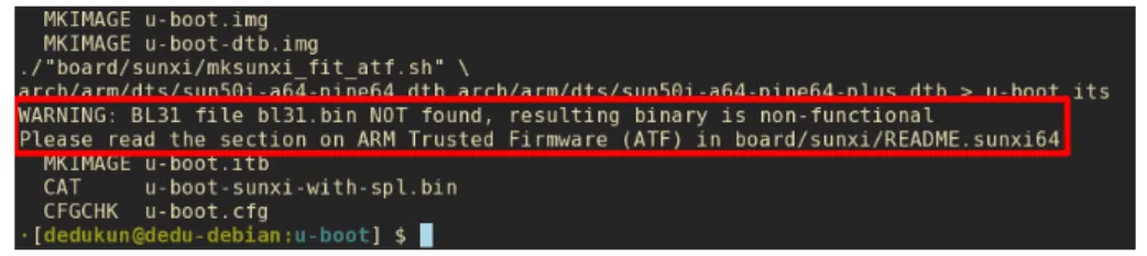
After we let the compilation finish, we can verify that the compilation contains a warning, as presented in Figure 3.1. This is because it is missing the PATH for the Boot Loader Stage 3-1 (BL31) [22, chapter 4.12], binary, which is required to have a fully functional bootloader.
Figure 3.1: U-Boot Missing BL31 Warning
Therefore, to compile this binary we need to run the code described in Code 5, which will first fetch the source files for the BL31 and then compile the binary with the required target and cross compiler. Finally, it exports the variable BL31 with the path of the built binary, which will then be used by the bootloader toolchain to retrieve this binary when needed.
$ git clone https://github.com/ARM-software/arm-trusted-firmware $ cd arm-trusted-firmware
$ CROSS_COMPILE=aarch64-linux-gnu- make PLAT=sun50i\_a64 bl31
$ export BL31="$PWD/build/sun50i_a64/release/bl31.bin"
Code 5: Compilation of the BL31 for sunxi A64 SoCs
After the BL31 had been properly compiled and exported, the BuildRoot was recompiled using the make command once again, inside the U-Boot root folder.
3.1.2 Changing the configurations
At this point we already know that the bootloader is compiling correctly. Thus, we will start by making our desired modifications to lower the system requirements. This can was achieved by running the Make target menuconfig, which will start a Terminal User Interface (TUI) that allows us to modify with the bootloader configurations. As such, we executed the following command ARCH=arm64 CROSS_COMPILE=aarch64-linux-gnu- make menuconfig
After the command is executed, a menu similar to the one in Figure 3.2 will appear in the terminal.
Thereupon we can start to do our modifications. One of the precautions we can take is to reduce the RAM clock speed, as well as the CPU clock frequency. To do so, first it is required to check the correspondent peripherals datasheet to verify the slowest clock speed supported, which in this case is 333Hz for the RAM and 408M Hz for the CPU.
To change RAM value, we need to first select the ARM architecture submenu, and in the option sunxi dram clock speed, change its default value to 333, as summarized in Code 6, which shows the menu progressing within the TUI, as well as the modified variable for the desired option.
ARM architecture --->
DRAM Type and Timing (DDR3 1333) ---> (333) sunxi dram clock speed
(3881915) sunxi dram zq value
Figure 3.2: U-Boot Menuconfig Home
Similarly, to change the CPU frequency, inside the Boot images submenu, we changed the option CPU clock frequency to 408000000.
After the desired changes to the configurations are done, we can then save them by selecting <Save> in the bottom of the menu. A recompilation is then needed to build the bootloader
binary with the latest modifications. This can be accomplished by executing make again. 3.1.3 Booting
At this stage, we can now deploy the bootloader to the test board. To achieve this, we flashed an SD Card, and booted from there.
However, before flashing, we first need to prepare an SD Card by deleting all of its partitions and formatting it, for example, as FAT322. This can be accomplished in Linux with GParted3.
After the SD Card is formatted, we will flash the compiled bootloader image, with the integrated Second Program Loader (SPL), which will copy the U-Boot from the SD Card to system RAM at boot time [23].
To do so, we executed the command in Code 7. The device /dev/sdX is being used here, as in later Codes, as a generic mountpoint for the SD Card in the build host machine.
$ sudo dd if=u-boot-sunxi-with-spl.bin of=/dev/sdX bs=1024 seek=8
Code 7: Flashing U-Boot
After the SD Card has been successfully flashed, we booted the board and started the validation of the core peripherals. To see the output from the board, we need to connect a
2FAT32 –https://support.microsoft.com/en-us/help/154997/description-of-the-fat32-file-system 3
GParted –https://gparted.org/
USB to TTL Serial converter, to the serial port of the board, as illustrated in Figure 3.3.
Figure 3.3: WiiPiiDo to PC Serial Connection
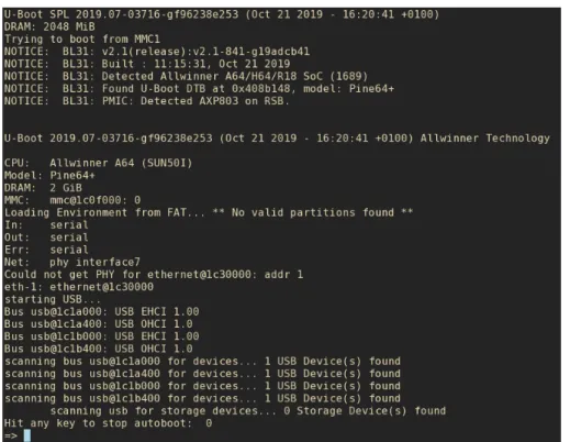
The image booted successfully, as shown in Figure 3.4. With this information, we can already validate that the CPU, RAM and SD Card Reader are working, as without these devices functioning, it would not be possible to boot from the SD Card. We also noticed that some USB where detected, as seen in the last lines of the output shown in Figure 3.4.
Figure 3.4: U-Boot First Boot
Depending on the installed U-Boot version, a few test commands exist in the Command Line Interface (CLI), which allow further testing [24]. An example of such command is the mtest command, which performs a simple RAM test, or the command mmc, which allows to do some basic read/write tests to the eMMC.
3.1.4 Boot using FEL
In the first revision of the board, a problem was detected in one of the prototypes with the SD Card Reader, which prevented us to boot the board from the SD Card. To alleviate this problem from disabling us to further test the rest of the board when the issue was being resolved, we made use of a special subroutine that exists in some Allwinner SoCs, including the Allwinner A64, that allowed us to boot directly over USB OTG, by loading the bootloader from the USB to RAM, enabling us to forgo the SD Card completely [26].
With this tool, we not only were able to test the bootloader, but the minimal Linux image as well, as FEL supports booting a complete system over USB, limited only by the board RAM size.
To use this mode, first we fetched the official tools from the sunxi repositories 4, and compiled the code. This was achieved by running the code in Code 8.
$ git clone https://github.com/linux-sunxi/sunxi-tools.git $ cd sunxi-tools
$ make
Code 8: Compiling Sunxi-tools
After the tools were compiled, we connected a USB OTG cable, with no power, to the board. Subsequently, we forced the board to enter the FEL subroutine, which can be accomplished in 5 ways [27]:
• Pressing a dedicated button
• By holding a standard button in a specific manner • By inputting special characters though serial console • Using a special SD Card which enter FEL mode • Having no valid boot image
In our case, WiiPiiDo has a dedicated button to enter FEL mode. Finally, we only need to execute the command described in Code 9, which will get the appropriate files and write them to the correct addresses in memory.
$ sudo ./sunxi-fel -v -p spl sunxi-a64-spl32-ddr3.bin write 0x44000 </path/to/arm-trusted-firmware/bl31.bin> write 0x4a000000 </path/to/u-boot/u-boot.bin> reset64 0x44000
Code 9: Upload Bootloader using FEL
Unfortunately, the AArch64 branch for the U-Boot SPL does not support FEL, since FEL is done entirely in AArch32. So, to boot the Allwinner A64 from FEL we need to combine the AArch32 SPL, with the previously compiled U-Boot and BL31, as referenced in the official documentation [28].
3.2 Creating a minimal Linux image
After the core peripherals validation was completed, a minimal Linux image was built.
4
Sunxi Tools Git Repository –https://github.com/linux-sunxi/sunxi-tools
The procedure for this build was similar to the U-Boot compilation, in which we will compile a minimal image, with minimal requirements. This will result in a lower building time, as well as to avoid possible kernel errors due to incorrect device integration when probing the hardware.
Therefore, to build the first complete Linux image, BuildRoot will be used, seeing that it allows full customization over the image to be built, and by default, it has a small image size compared to other building environments, and consequently, a faster compilation time, as it has a lot of kernel, U-Boot, and other settings disabled by default.
The source files for the build environments was fetch from the official sources [29]. All of the system requirements where also installed, which where found in the official documentation [17, chapter 2].
3.2.1 Building the image
As referred in 2.5.1, BuildRoot consist of a set of Makefiles, which will create the complete Linux Image that can then be flashed to the board, including the bootloader and the kernel with respective Device Tree Blobs (DTBs), the root file system, as well as BusyBox, which provides most of the GNU utilities in a single small executable [30].
Similarly to U-Boot, BuildRoot also has configuration files that contain the configurations for different boards already supported by the environment.
We will be using the same approach as we used with the bootloader, and first compile an image for the Pine A64 Plus, to serve as a base for the configurations.
As such, to build the default BuildRoot image for the Pine A64 Plus, we need to execute in the command line the Code 10.
$ git clone git://git.busybox.net/buildroot $ cd buildroot
$ make pine64_defconfig $ make
Code 10: Compilation of BuildRoot using the configuration file pine64_defconfig
The chosen building configurations already define the target board, so there is no need to specify the architecture and compiler to used, contrarily to the U-Boot process.
3.2.2 Configuration menu
After making sure that BuildRoot is compiling correctly, we started making our desired modifications to the image. Opposite to the U-Boot configuration menu, BuildRoot provides several interfaces to change its configurations, from curses (menuconfig) and ncurses (nconfig) TUIs, to interactive Qt (xconfig) and GTK (gconfig) interfaces.
BuildRoot can also independently invoke the configuration menu for the U-Boot (uboot-menuconfig), Kernel (linux-menuconfig), BusyBox (busybox-menuconfig) and uClibc (uclibc-menuconfig), which is the C library installed by default.
In our case, we will be using the curses configuration menu, so we start the TUI by running make menuconfig, which produces a display similar to the one in Figure 3.5.
Figure 3.5: BuildRoot menuconfig Home
Some of the sub menus to take note are:
• System configuration – Configuration for the target system, such as the PATH, hostname, shell, locale, etc.
• Kernel – Top configuration for the kernel (the version to use, kernel patches, device tree blob, etc). For a more in-depth configuration we use the kernel configuration menu (linux-menuconfig).
• Target packages – The packages to be included in the filesystem. The majority of the coreutils are in BusyBox (busybox-menuconfig).
• Filesystem images – Configurations for the file system (ext4, btrfs, etc).
• Bootloaders – Top configuration for the bootloader (the version to use, the defconfig file, etc). For a more in-depth configuration we use the U-Boot configuration menu (uboot-menuconfig).
The modifications done in this stage result in:
Change CPU Governor As it was done in the U-Boot configuration, we will start by changing the CPU Frequency. In the Kernel however, there is not a fixed CPU Frequency value, but a CPU Governor, or in other words, the frequency profile. By default, the CPU is using an ondemand or performance profile, which scale the CPU Frequency by the current demand from the system, or have it always using the max frequency, respectively. We changed this option to powersafe, which will make the CPU always use the lowest frequency supported. This option belongs in the Kernel configurations, which can be called using the Make target linux-menuconfig. Inside the submenu CPU Frequency scaling in CPU Power Management, we modify the Default CPUFreq governor to powersafe, which will tell the Kernel to use the lowest supported CPU frequency. A summary of the TUI submenus if demonstrated in Code 11.
CPU Power Management ---> CPU Frequency scaling --->
Default CPUFreq governor (powersafe) --->
Code 11: Change the Kernel CPU Governor
Change the DTSs used Another option that we changed is the DTS used by the Kernel and bootloader. This is the because the version of BuildRoot in use does not contain a configuration file for the Pine A64 Plus, only the Pine A64, which belongs to the same family of SBCs, however, the configurations for this board exist internally in the U-Boot and Kernel repositories. As such, we can modify the BuildRoot options that states which DTS or configuration file to use in both the Kernel and U-Boot. In the case of the Kernel DTS definition, this option resides in the BuildRoot Configurations, inside the Kernel submenu, by the name of In-tree Device Tree Source file names, as summarized in Code 12. The desired value is allwinner/sun50i-a64-pine64-plus. Kernel --->
(allwinner/sun50i-a64-pine64-plus) In-tree Device Tree Source file names Code 12: Changing the Kernel DTS in BuildRoot As for the, this modifications is described in Code 13. Kernel --->
[*] U-Boot
(pine64_plus) Board defconfig
Code 13: Changing the U-Boot configuration file in BuildRoot
Apply the modifications made to the bootloader The modifications made to the boot-loader can be applied once again, following the steps described in Section 3.1.2, using the U-Boot configurations menu target uboot-menuconfig. Alternately, we can later, before booting the image, overwrite the bootloader compiled by the BuildRoot, with the one compile previously, by running the command in Code 7.
3.2.3 Booting
After a successful compilation, we can now boot the built image. All of built binaries reside in the folder buildroot/output/images, such as the bootloader, kernel, rootfs, etc, as demonstrated in Figure 3.6.
Figure 3.6: BuildRoot output images
BuildRoot will also generate the file sdcard.img, which contains the complete image in a single file. This way, to flash the image in a formatted SD Card, we execute the Code 12.
We can now boot the new image, and do further validations to the board devices. The default login credentials are username root, and no password.
$ sudo dd if=sdcard.img of=/dev/sdX bs=1M status=progress
Code 14: Flashing the BuildRoot Image
3.3 Peripherals integration
At this stage, we can now start doing a more thorough validation of each peripheral present in the board. To make this process more systematic, an approach was defined, which was based on the principle that when a peripheral is not working correctly, there are generally only three possible locations where modifications have to be made, which are:
• The Kernel configurations • The DTS
• The Device Driver (Firmware)
The outlined approach is illustrated in Figure 3.7.
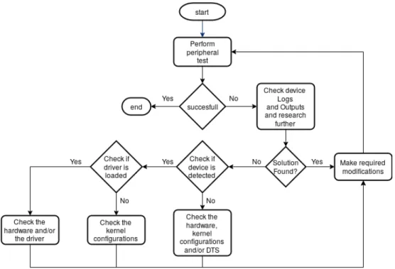
Figure 3.7: Device Validation Approach
To start the validation of a specific peripheral, a respective validation test needs to be specified. For example, to validate a GPIO port, a test to make sure that the GPIO is working correctly is to use the file system interface to manipulate an individual port and read/write values from/to it. Once this test is defined we can then perform it. If the test was successful, the peripheral is validated and working correctly, if not, we retrieve the outputs from the test, as well as possible kernel and/or system logs, provided, for example, by the command dmesgand the file /var/log/syslog, respectively. Once this information is gathered, we can then research further for a possible solution by consulting available resources, such as online documentation or forums, as well as other developers. If a solution was found in this process,
we then apply it and try the validation test again. If no solution was found, we can try to narrow down the potential causes of the problem by doing the following validations:
• Verify if the peripheral is being detected. If the device is not being detected correctly, there are generally three possible causes:
– An hardware problem, such as the device not being powered or soldered correctly. – An error in the kernel configuration.
– An error in the DTS.
• Verify if the peripheral driver is being loaded. If the device driver is not being loaded, then generally the problem must be in the kernel configurations.
Finally, if these validations were successful, then the problem must be in the device driver. Errors in the device driver are the last possibility to consider in this approach because, unlike the kernel configurations and the DTS, the device driver should generally be independent of the particular target board or build environment being used.
3.3.1 Example: GPIO port
As an example of the device validation approach, when we tried to use a GPIO port as an output pin, we noticed that the file system interface for the device was absent (see Figure 3.8). Therefore, the Kernel configurations where checked and noted to not have the sysfs interface
Figure 3.8: Missing GPIO sysfs interface. The /sys/class/gpio directory is absent. for the GPIOs activated. The problem was easily fixed by toggling the sysfs interface option in the GPIO Support inside the Device Drivers submenu of Kernel configurations (Code 15). Device Drivers --->
GPIO Support --->
[X] /sys/class/gpio... (sysfs interface)
Code 15: Activating the sysfs interface for the GPIOs
3.4 Synthesis
In this chapter we looked over and defined a process to rapidly validate the components of the board in situations of simultaneous hardware and firmware development. We argue that in
such cases the development should proceed in stages, starting from a simple bootloader, moving on to a minimalistic but complete Linux image and finally, ending with the development of the final images in the chosen building environments. In each stage, different building environments may be used, allowing the developer to profit from the distinct advantages of each environment in different stages of development.
CHAPTER
4
Building The Final Images
This chapter presents the Armbian and Yocto building environments, as well as some of the modifications that were implemented to support the WiiPiiDo board.With the in aim to compare the chosen build environments, we are going to show in some detail the process used to compile the final images.
4.1 Building an image in Armbian
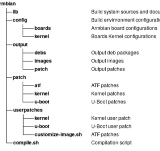
As it was discussed in the Section 2.5.3, Armbian is a Debian-based distribution specially develop for ARM SoCs. The build system consists of a series of shell scripts, and the structure of the environment is summarized in Figure 4.1.
Figure 4.1: Armbian Folder Structure
Armbian has two types of configurations that can be made. There are user configurations, which are associated to the developers using the environment and are meant to be personal
modifications, associated only to the specific repository being used. Additionally, there are Armbian official board configurations, which are the permanent configurations associated with the build environment in itself. As such, the userpatches directory contains the user configurations, and the patch and config folders contain the Armbian official configurations. 4.1.1 Building a test image
To compile an Armbian image, we first fetched the source files [31] and used the script compile.sh. Armbian supports several alternative ways of building images:
• building natively in a host machine;
• building in a virtual machine using VirtualBox, for example;
• building with Vagrant, which manages VirtualBox images in an easily repeatable way; • building inside a Docker container.
In our case, we decided to compile natively in our host machine, so that we could later fairly compare the compilation time between building environments, and to generally compile the Armbian images faster. To start the building process, we executed the commands in Code 16. The compilation option NO_HOST_RELEASE_CHECK=yes was required in our case, because we did not use the officially supported host OS.
$ git clone --depth 1 https://github.com/armbian/build armbian $ cd armbian
$ ./compile.sh NO_HOST_RELEASE_CHECK=yes
Code 16: Armbian Quick Start
After the compilation started, a TUI will open asking a few options that need to be picked before the compilation can start. This options are presented in the following list, as well as selections that were made.
1. The output of the compilation • Just the bootloader and kernel • The full image [selected]
2. To open the kernel configuration menu before compiling • Yes
• No [selected]
3. The target board [selected pine64] 4. The kernel version
• default Legacy kernel (3.10.y)
• next Mainline kernel (4.19.y) [selected] 5. The distribution and its release to build
• stretch Debian 9 [selected] • buster Debian 10
• xenial Ubuntu 16.04 • bionic Ubuntu 18.04
6. The type of image
• Server image [selected] • Desktop image
7. The image installed packages • Standard
• Minimal image with less installed packages [selected]
As an alternative, we could also give this information to Armbian as command line options, the same way as it was done previously to stop the host machine verification. In a command line only format, the options selected previously are equivalent to the following command:
./compile.sh NO_HOST_RELEASE_CHECK=yes BOARD=pine64 BRANCH=next RELEASE=stretch
BUILD_MINIMAL=yes BUILD_DESKTOP=no KERNEL_ONLY=no KERNEL_CONFIGURE=no
The full list of the building options can be found in the official documentation [32, Build Options]. The output from the compilation is demonstrated in Figure 4.2.
Figure 4.2: Armbian Compilation
4.1.2 Adding support for the WiiPiiDo
Once its verified that an image compiled successfully, we started adding the support for the WiiPiiDo board. This is mainly focused in four areas:
• Kernel and bootloader building configurations • Kernel and bootloader DTSs
• Kernel and bootloader source code modifications
• Compiled image settings, like the target file system, installed packages, default user configurations, etc
These modifications are also divided in two phases that were discussed previously, which are respectively the user modifications and the Armbian official configurations. We started by focusing first in making our modifications as user patches, and later adapt them to be able to be added as Armbian official support.
Changing the build configurations To modify the kernel options, we invoked the kernel configuration menu by using the command line option KERNEL_CONFIGURE=yes, in conjunc-tion with the opconjunc-tionKERNEL_KEEP_CONFIG=yes, which tells Armbian keep the configurations
between compilations. After the modifications where validated, we copied the resulting file .config to userpatches/linux-sunxi64-next.config [32, User Configurations]. For the bootloader, there is no direct interface as the one used in the Kernel. In this case, we had to make a patch in the U-Boot source code. Alternately, we could have changed the U-Boot Repository used, for a custom repository with the changes made in the previous built U-Boot image. However, for initial development, we flashed the previous working U-Boot image, as in Code 7.
Changing the DTSs The development of the DTS is easy in Armbian as it supports Device Tree Overlays by default. As such, we can add the overlays to the SBC, and test them without the need to recompile a new image. The over-lays are located at /boot/dtb/allwinner/overlay, and can be compiled and ac-tivated using the command armbian-add-overlay, that has the following syntax armbian-add-overlay <overlay_file.dts>. The file /boot/armbianEnv.txt is used to acti-vate/deactivate, as well as to pass parameters to the overlays if needed.
Once again, there is no simple way to change the bootloader DTS. To do modifications to the bootloader DTS we can use the same methods as the ones described previously. Changing the source code The method to change the source code of the kernel and bootloader is the same, which is to create patches with the desired modifications from the sources.
To do this, Armbian provides an interactive patch creating tool, which is started when passing the option CREATE_PATCHES=yes to the build system. Armbian will, right before starting the compilation, wait for the user to make its desired modifications to the kernel and bootloader respectively. Once the modifications are made, it will generate a patch file with them and apply it, as demonstrated in Figure 4.3.
Figure 4.3: Armbian Source Files Patch
It is important to remember that Armbian is using thegit diffcommand to generate the patches, so modifications made in files that are present in .gitignore will not be de-tected. Once the patches are created, they will be placed in the directory outputs/patch. If further compilations are still executed with the option CREATE_PATCHES=yes, the build system applies the previously generated patches, however, if it is not present, they will not be applied. To make these patches permanent, we placed them in the directories userpatches/kernel/sunxi-next and userpatches/u-boot/u-boot-sunxi, for the kernel and bootloader patches respectively.
Changing the image settings To change the image settings, we made use of the file userpatches/lib.config, which redefines some of the configurations used by Armbian,
such as the kernel and bootloader version used, as well as the initially installed packages [32, User provided configuration], as shown in the example in Code 17.
PACKAGE_LIST_ADDITIONAL="$PACKAGE_LIST_ADDITIONAL nodejs" # Add nodejs
BOOTSOURCE=https://github.com/Globaltronic/u-boot.git # Change the U-Boot source
BOOTCONFIG=wiipiido_defconfig # Change the U-Boot defconfig
Code 17: Changing Armbian Configurations
4.2 Building an image in Yocto
Yocto is different from Armbian, as Yocto is not a distribution in itself, but a set of tools that allow the developer to create a full Linux Distribution. To do so, Yocto defines metadata, or sets of instructions and configurations used by the OpenEmbedded’s build system, bitbake. Related recipes are then organized together in different layers, where there are:
• BSP layers, which contain the recipes necessary to add support for a system • Application layers, that contain the necessary recipes to install an application • Distribution layers
To better understand how to use the environment, we will first look at Poky [33], the reference repository that is recommended to be used as the base for any Yocto image. It contains the build system, bitbake, as well as the core recipes that will be used in the majority of the projects. The structure for this directory is summarized in Figure 4.4.
Figure 4.4: Poky Repository Structure Some of the files and directories to take note from this Figure are:
• The oe-init-bulid-env script, which is used to initialize the build environment. • The directory build/conf, that contains the main configurations for the image to be
compiled, such as the configuration of the target board, the selection of the packages to be installed, the meta layers to included, as well as the target filesystem, etc.
• The meta-* directories, which represents a bitbake layer. A layer can then be expanded further, as illustrated in Figure 4.5.
Figure 4.5: Yocto BSP Layer Structure In this figure it is summarized a BSP layer, which consist in:
The conf directory This directory has the general configurations for the layer, such as the name of the layer, recipes path, the priority of the layer, which is used to chose a layer from multiples with the same name, and the layer’s compatibility, i.e., in which versions of Poky does the layer work on. Also present in this directory are the board specific configurations, that contain the version and configurations of the kernel and bootloader to use, as well as the target file system, pre-installed packages, recipes dependencies, etc. Code 18 is a snippet of a board configuration file. In Appendix A, Code 30 there is the full configuration file that ended up being used in WiiPiiDo.
PREFERRED_PROVIDER_virtual/kernel ?= "linux-wiipiido"
PREFERRED_VERSION_linux-wiipiido ?= "4.19%"
KERNEL_CLASSES = "kernel-fitimage"
KERNEL_IMAGETYPE = "fitImage"
KERNEL_DEVICETREE = "allwinner/sun50i-a64-wiipiido.dtb"
MACHINE_EXTRA_RRECOMMENDS += "kernel-modules linux-firmware-brcm43430"
IMAGE_FSTYPES += "wic"
WKS_FILE ?= "wiipiido-bsp-image.wks"
Code 18: Yocto BSP Board Configuration Snippet Example.
The recipes-* directory This directory has the recipes that are present in the layer. Each recipe contains at least a *.bb file, which is the recipe in itself, and may have additional files used by the recipe in the separate folder files.
Each recipe contains a set of tasks that have the information of the instructions to be accomplished in a given step of the building process. The most important tasks that exist in a recipe are [34]:
1. do_fetch – Fetches the source code
2. do_unpack – Unpacks the source code into a working directory 3. do_patch – Locates patch files and applies them to the source code
4. do_configure – Configures the source by enabling and disabling any build-time and configuration options for the software being built
5. do_compile – Compiles the source in the compilation directory
6. do_install – Copies files from the compilation directory to a holding area 7. do_package – Analyzes the content of the holding area and splits it into subsets
based on available packages and files
8. do_package_write_rpm – Creates the actual RPM packages and places them in the Package Feed area
Recipes can also inherit definitions from other recipes, and Yocto already provides base recipes for common building utilities used in most applications like Autotools, CMake, etc [35, Chapter 3.3.10]. Beyond the tasks definitions, the recipe also has information about the sources and licensing. Code 19 contains the source file of a simple recipe.
SUMMARY = "Simple helloworld application"
SECTION = "examples"
LICENSE = "MIT"
LIC_FILES_CHKSUM = "file://${COMMON_LICENSE_DIR}/MIT;md5=0835ade698e0bcf8506ecda2f7b4f302"
SRC_URI = "file://helloworld.c" S = "${WORKDIR}" do_compile() { ${CC} helloworld.c -o helloworld } do_install() { install -d ${D}${bindir}
install -m 0755 helloworld ${D}${bindir}
}
Code 19: Yocto Recipe Example [35, Chapter 3.3.21.1].
The wic directory The wic directory contains the partitioning configurations. An example configuration is presented in Figure 20.
part spl --source rawcopy --sourceparams="file=u-boot-sunxi-with-spl.bin"
--ondisk mmcblk --no-table --align 8
part /boot --source bootimg-partition --ondisk mmcblk0 --fstype=vfat --label wiipiido --active --size=100M --align 20480
part / --source rootfs --ondisk mmcblk0 --fstype=ext4 --label platform --align 4096
Code 20: Wic Partitioning Configurations.
4.2.1 Building a test Image
Similarly to the other images that were created with the different build environments, first we started by building a test image, making use of Poky as the reference distro, as mentioned in the last section. As such, we first fetched the Poky repository from the Yocto Project, making sure we used the last stable version, which at the time of this development was version
![Figure 1.2: Linux Distribution preference [4]](https://thumb-eu.123doks.com/thumbv2/123dok_br/15938748.1096003/22.892.267.603.209.515/figure-linux-distribution-preference.webp)
![Figure 1.3: The WiiPiiDo Board Components [8].](https://thumb-eu.123doks.com/thumbv2/123dok_br/15938748.1096003/25.892.210.706.140.559/figure-the-wiipiido-board-components.webp)