(Recebido em 25/10/2010; Texto inal em 11/11/2010).
(Algumas Armadilhas na Soldagem de Aços Inoxidáveis Duplex)
Demian J. Kotecki1
1 Retired from The Lincoln Electric Company, USA, and President of Damian Kotecki Welding Consultants, Inc., Mentor, Ohio, USA
Abstract
Duplex stainless steels (DSS, including super duplex stainless steels {SDSS}) have proven to be very useful engineering materials, albeit with somewhat different welding requirements than those of the more familiar austenitic stainless steels. Despite a generally good track record in welding of duplex stainless steels, certain pitfalls have been encountered with enough frequency that they deserve review. Inappropriate base metal speciication often leads to unsuitable heat affected zone (HAZ) properties. Autogenous fusion zones are also of concern. This issue centers around nitrogen limits. The most frequently encountered is applying the UNS S31803 composition for 2205 DSS, instead of the S32205 composition. Inappropriate welding heat input arises most frequently with SDSS. While 0.5 to 1.5 kJ/mm is a normal heat input recommendation for SDSS, either a root pass or many small beads towards the low end of this heat input range tends to result in precipitation and/or secondary austenite formation in weld metal subjected to repeated thermal cycles from multiple weld passes. Inappropriate PWHT occurs when the enhanced nickel iller metals (typically 9% Ni) are used. DSS are not normally given PWHT, but extensive forming of heads, for example, or repair welding of castings, may require a postweld anneal. Speciications such as ASTM A790 and A890 call for annealing at 1040°C minimum, and the fabricator tends to use temperatures close to that minimum. However, the enhanced nickel iller metals require higher temperatures to dissolve sigma phase that forms during heating to the annealing temperature.
Keywords: Duplex stainless steel, Ferrite-austenite balance, Fusion zone, Heat-affected zone, Heat input, Heat treatment, Nitrogen, Precipitation, Welding.
Resumo: Aços inoxidáveis duplex (AID, incluindo os aços super duplex, AISD) provaram ser materiais de engenharia muito úteis, embora com requerimentos de soldagem em alguma medida diferentes daqueles dos aços inoxidáveis austeníticos mais usuais. Apesar do histórico geralmente bom dos aços inoxidáveis duplex quanto a soldagem, algumas diiculdades têm sido encontradas com uma frequência relativamente alta para justiicar um exame mais detalhado destas. A especiicação inadequada do metal base frequentemente resulta em propriedades inadequadas da zona termicamente afetada (ZTA). Zona fundida autógena é também motivo de preocupação em função de limites no teor de nitrogênio. A situação mais comumente encontrada é o uso de UNS S31803 para o AID 2205 no lugar de S32205. O uso de um aporte térmico inapropriado ocorre mais frequentemente com AISD. Embora uma faixa de 0,5 a 1,5 kJ/mm seja uma recomendação normal de aporte térmico para AISD, tanto o passe de raiz como muitos pequenos cordões depositados no limite inferior desse intervalo de aporte térmico tendem a resultar em precipitação e/ou formação de austenita secundária no metal de solda submetido a ciclos térmicos repetidos. Tratamento térmico após soldagem (TTAT) inapropriado ocorre quando metais de adição de maior teor de níquel (tipicamente 9%) são usados. Estes tratamentos não são normalmente aplicados a AID, mas a conformação severa de cabeças, por exemplo, ou a soldagem para reparo de fundidos, pode requerer um recozimento após a soldagem. Especiicações como a ASTM A790 e a A890 indicam um mínimo de 1040ºC para o recozimento e o fabricante tende a usar uma temperatura próxima deste mínimo. Contudo, o metal de adição de maior teor de níquel requer temperaturas mais elevadas para dissolver a fase sigma durante o aquecimento para a temperatura de recozimento.
Palavras Chave: Aço inoxidável duplex, balanço ferrita-austenita, zona fundida, zona termicamente afetada, aporte térmico, nitrogênio, precipitação, soldagem.
1 Introduction
Duplex ferritic-austenitic stainless steels have been in existence for nearly 80 years. These alloys are characterized by solidiication as essentially 100% ferrite, and austenite must nucleate and grow in the solid state. Early alloys, such
resistance. Autogenous weld metal suffered from the same deiciency.
In the 1980s, the importance of nitrogen addition to the DSS base metal became fully realized, and it became normal to specify minimum nitrogen requirements. With appropriate nitrogen content in the base metal, and over-alloying with nickel in the weld iller metal, weldments with approximately equal amounts of austenite and ferrite, resulting in good mechanical properties and good corrosion resistance, could be obtained in the as-welded condition. The main limitation on the welding process then became heat input appropriate to obtain the proper austenite-ferrite balance in the HAZ by obtaining the proper cooling rate. Heat input that was too low could still result in excessive ferrite, while heat input that was too high could result in precipitation of intermetallic phases. It has become common to recommend heat input of 0.5 to 2.5 kJ/mm for 22% Cr DSS
[2], and 0.5 to 1.5 kJ/mm for 25% Cr DSS [3].
While most duplex stainless steel weldments are put into service in the as-welded condition, there are at least two situations where postweld heat treatment (annealing) is often required. DSS castings are almost invariably annealed, and if casting defects are repaired by welding, the weld must generally be annealed also. And large welded heads that are either cold or hot formed after fabrication by welding may require annealing.
There are pitfalls for the unwary in all three of these areas: base metal speciication, welding heat input limits and postweld annealing practices.
2 Pitfall 1: Inappropriate Base Metal Speciication
For the past quarter century, probably the most popular DSS has been the alloy commonly known as 2205. The literature Table 1 – Composition ranges for 2205 DSS.
UNS Designation Chemical Composition Range, Weight % (single value is a maximum)
C Mn P S Si Cr Ni Mo N
S31803 0.030 2.00 0.030 0.020 1.00 21.0 to 23.0 4.5 to 6.5 2.5 to 3.5 0.08 to 0.20
S32205 0.030 2.00 0.030 0.020 1.00 22.0 to 23.0 4.5 to 6.5 3.0 to 3.5 0.14 to 0.20
is replete with descriptions of this alloy according to the UNS S31803 composition range. However, the nitrogen content associated with UNS S31803 can be as low as 0.08%, a level that has proven to be too low for good HAZ and autogenous fusion zone properties in the as-welded condition. Recognizing this issue, the ASTM has instead, since the year 2000, deined 2205 by UNS S32205 [4]. Table 1 shows the composition ranges for UNS S31803 and UNS S32205. It can be noted that, in addition to the increased minimum nitrogen requirement for S32205 as compared to S31803, the minimum chromium and molybdenum limits have been increased.
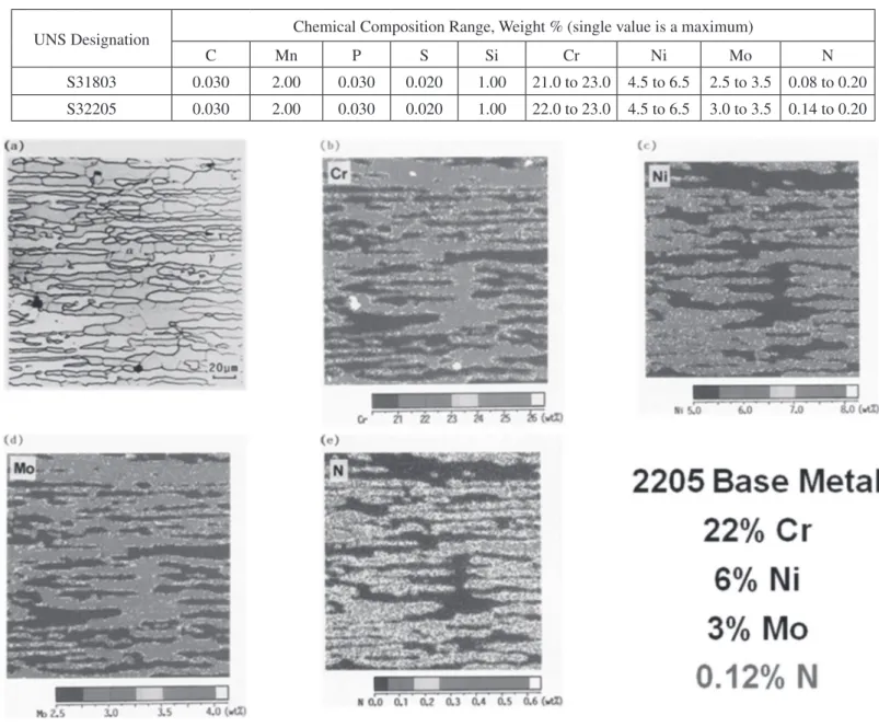
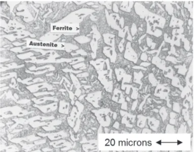
The importance of nitrogen in controlling the ferrite/ austenite phase balance during welding has been well illustrated by Ogawa and Koseki [5]. Figures 1 through 3 are taken from their report. Figure 1 shows the microstructure and alloy element partitioning between the ferrite phase and the austenite phase in a wrought composition that conforms to UNS S31803 but not to UNS S32205. The nitrogen, at 0.12%, is too low for the S32205 composition range. In Figure 1(a), the ferrite is the darker grey phase while the austenite is nearly white. It is readily seen that chromium and molybdenum are enriched in the ferrite phase while nickel and nitrogen are enriched in the austenite phase.
In particular, chromium content is approximately 25% in the ferrite but only 20% in the austenite {Figure 1(b)}, molybdenum
content is approximately 3.5% in the ferrite but only 2.5% in the austenite {Figure 1(d)}, while nickel content is approximately 7.5% in the austenite but only 5% in the ferrite {Figure 1(c)}, and nitrogen content is approximately 0.3% in the austenite and virtually 0% in the ferrite {Figure 1(e)}. This is essentially the equilibrium phase distribution. It is somewhat layered because the steel has been hot rolled.
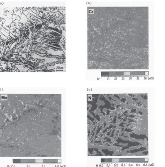
grains, where the nitrogen is trapped without access to austenite, precipitates are visible in Figure 2(a) which turn out to be chromium nitrides. The combination of the large ferrite grains and the chromium nitride precipitates is very damaging to the toughness and corrosion resistance of the fusion zone.
The fusion zone solidiies as essentially 100% ferrite, as noted previously. Then when transformation to austenite begins, diffusion is necessary. Chromium, nickel and molybdenum, being substitutional elements, diffuse relatively slowly in the solid state, so that they cannot partition between ferrite and austenite under normal weld cooling conditions. Nitrogen, however, is an interstitial element that diffuses on the order of 100 times as fast as the substitutional elements. As a result, it has some ability to partition to austenite, albeit incompletely for the composition shown in Figure 2.
The hottest part of the HAZ in this 0.12% nitrogen material behaves similarly to the weld metal. In particular, it forms virtually 100% ferrite, then must transform in part to austenite, in the solid state. So it too tends to form large ferrite grains with mainly austenite platelets forming along the prior ferrite grain boundaries. While the composition of the fusion zone can be manipulated by selection of higher nickel iller metal to speed up the formation of austenite, little can be done for the HAZ. As
a result, compositions of this sort are best avoided for optimum properties in as-welded construction.
Figure 3 shows the microstructure and alloy element distribution of the GTA fusion zone of a 2205 alloy meeting the composition limits of both UNS S31803 and S32205 by virtue of its higher nitrogen content than that of the composition shown in Figure 2. The higher nitrogen content of the weld metal of Figure 3 (0.18% as compared to the 0.12% of Figure 2) dramatically changes the as-welded microstructure. In particular, it can be clearly seen in Figure 3(a) that much more austenite formed than in Figure 2(a), and the austenite is scattered throughout the original large ferrite grains, rather than being largely limited to the original ferrite grain boundaries.
Table 2. Composition limits for Alloy 255.
UNS Designation
Chemical Composition Range, Weight % (single value is a maximum)
C Mn P S Si Cr Ni Mo N Cu
S32550 0.04 1.50 0.040 0.030 1.00 24.0 to 27.0 4.5 to 6.5 2.9 to 3.9 0.10 to 0.25 1.50 to 2.50
S32520 0.030 1.50 0.035 0.020 0.80 24.0 to 26.0 5.5 to 8.0 3.0 to 4.0 0.20 to 0.35 0.50 to 2.00
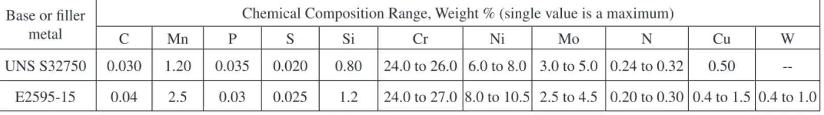
Table 3 – UNS S32760 and E2595-15 composition ranges.
Base or iller metal
Chemical Composition Range, Weight % (single value is a maximum)
C Mn P S Si Cr Ni Mo N Cu W
UNS S32750 0.030 1.20 0.035 0.020 0.80 24.0 to 26.0 6.0 to 8.0 3.0 to 5.0 0.24 to 0.32 0.50
--E2595-15 0.04 2.5 0.03 0.025 1.2 24.0 to 27.0 8.0 to 10.5 2.5 to 4.5 0.20 to 0.30 0.4 to 1.5 0.4 to 1.0
N alloy, and, by beginning diffusion and transformation at the higher temperature, molybdenum and chromium can diffuse more rapidly and have somewhat longer time to do so. It should also be noted in Figure 3(a) that the original coarse ferrite grain size has been broken up by the formation of austenite platelets throughout the original ferrite grains. With the ferrite grains broken up into smaller units by the austenite platelets interior to the original ferrite grains, toughness is improved. And without chromium nitride precipitates, corrosion resistance is improved. The same situation occurs in the hottest part of the HAZ. As a result it can be concluded that the higher nitrogen UNS S32205 composition of Figure 3 is clearly superior to the lower nitrogen UNS S31803 composition of Figure 2.
Accordingly, it should be abundantly clear that UNS S31803 is an inappropriate base metal speciication for service in the as-welded condition. UNS S32205 should be speciied instead.
UNS S31803 is not the only inappropriate base metal speciication for welded fabrication among the duplex stainless steels. The same situation exists with the alloy commonly known as 255, under the composition limits of UNS S32550. Table 2 compares the composition limits of UNS S32550 with those of UNS S32520, which overlap quite substantially. But the minimum nitrogen of UNS S32520 is considerably higher than that of UNS S32550, so that it should be abundantly clear that UNS S32520 is a superior speciication for use in the as-welded condition. Alternately, one could use the UNS S32550 speciication but restrict nitrogen to the upper part of the composition range.
3 Pitfall 2: Inappropriate Welding Heat Input
The conventional wisdom, as regards welding heat input, is that, for welding of the 22% chromium DSS alloys, heat input should be restricted to 0.5 to 2.5 kJ/mm [2], and for welding of the 25% chromium SDSS, heat input should be restricted to the range of 0.5 to 1.5 kJ/mm [3]. The lower heat input limit is imposed due to inadequate formation of austenite, even with high nitrogen alloys, under very rapid cooling rates. The upper heat input limit is imposed due to a tendency for precipitation of intermetallic compounds within the ferrite under slow cooling
conditions, a tendency which is greater in 25% Cr SDSS than it is in 22% Cr DSS.
Karlsson notes that the tendency for precipitates to form during welding, in the higher nitrogen 22% Cr DSS such as UNS S32205, is low enough that there is little risk as long as the heat input restriction noted above is followed [6]. However, he notes further that, with the 25% Cr SDSS, even the restriction of welding heat input to 0.5 to 1.5 kJ/mm does not guarantee freedom from precipitates in a multipass weld. Multiple weld reheating cycles can produce precipitation of chromium nitrides, secondary austenite and various intermetallic compounds including sigma phase in these highly alloyed steels.
An example of inappropriate welding heat input in 25% Cr SDSS from the author’s personal experience involved UNS S32750 (popularly known as Alloy 2507) multipass welded with AWS A5.4/A5.4M class E2595-15 covered electrodes. Table 3 lists the composition ranges of the base metal and electrode speciications. Note that the iller metal includes small additions of Cu and W, and otherwise matches the composition of the base metal except that the iller metal, as is common practice, is enriched in nickel to promote austenite formation in the as-welded condition. This iller metal/base metal combination is recommended by many iller metal manufacturers.
The plate thickness for the procedure qualiication tests was 9.5 mm. The joint preparation was a single-V groove, 60 degree included angle with a 1.5 mm root opening and a 3 mm root face. For the original procedure qualiication tests, 3.2 mm electrodes were used. After illing the groove with 10 weld passes, the root side was back-gouged to sound metal and inished with 2 passes. Welding heat input averaged about 0.7 kJ/mm for all passes. Sub-size (8 mm thick) Charpy V-notch specimens were taken from the weld metal and HAZ and tested at -40°C. The impact test requirement was 27 J, which the HAZ comfortably exceeded. But in the initial test and in a repeat test of the weld metal, two of three Charpy V-notch specimens failed to meet 27 J.
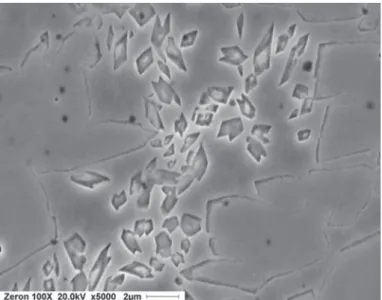
mid-thickness of the test coupon. Extensive angular precipitates, within the ferrite only, are readily apparent. No attempt was made to identify exactly which precipitates are present. It was concluded that the precipitation was brought about by the numerous reheat cycles involved in welding the test coupon in a total of 12 passes.
Accordingly a new procedure qualiication test was conducted, using the same joint design and electrodes. But the welding travel speed was reduced so that the welding heat input was about 1.2 to 1.3 kJ/mm, and the joint was completed in 4 weld passes from the top side and a single pass in the back-gouged root. The same sub-size Charpy V-notch impact specimens averaged about 45 J at -40°C, comfortably exceeding the 27 J requirement. The microstructure was found to be virtually free of all precipitates.
Root runs in pipe present a special case of inappropriate heat input possibilities. Welders of carbon steel pipes are trained to make the root run at rather high travel speed, usually using cellulosic electrodes in the vertical-down method, and to follow this up with a high heat input “hot pass” which serves to prevent hydrogen induced cracking in the carbon steel. But a low heat input root pass followed by a higher heat input “hot pass” tends to overheat the root pass and result in precipitation of intermetallic compounds in the root pass of SDSS. Since the root pass surface is the one usually exposed to the corrosive media in service, this can be a very dangerous situation. Intermetallic compounds buried within the joint away from an exposed surface, although they are damaging to toughness, are not nearly as dangerous as intermetallic compounds in the root pass because the former are not normally exposed to the corrosive media, while the latter are. A good practice with DSS and especially SDSS pipe is to put in the root pass with more heat input than the irst few ill passes [7-8]. A root pass of about 6 mm thickness has been found to work well [7].
Figure 4. Angular precipitates in the ferrite of E2595-15 reheated weld metal.
4 Pitfall 3: Inappropriate Postweld Heat Treatment
If a welded casting, or a welded and formed head, requires postweld heat treatment, the usual nickel-enriched iller metal, combined with inappropriate annealing temperature that meets base metal speciications, offers another pitfall for the DSS fabricator. (9% Ni is common in otherwise matching iller metals for DSS, as indicated for the E2595-15 iller metal in Table 3.) There is some variation in annealing requirements, but a common requirement is for annealing at 1040°C, minimum, followed by water quench from the annealing temperature [9]. The pitfall stems from the not-well-known fact that higher nickel raises the solvus temperature for the sigma phase that almost invariably forms in DSS during heating towards the annealing temperature. The nickel-enriched weld metal alone is at risk in this situation.
Figure 5 shows the effect of nickel on the sigma solvus temperature for 25% Cr – 3.5% Mo alloys, as given by Grobner [10]. While the alloys used in developing this diagram did not include alloy elements such as Mn, Si and N, it is qualitatively suitable for understanding the effect of nickel. It clearly shows that the sigma solvus temperature increases with increasing nickel content. In particular, it indicates that the sigma solvus temperature can be expected to be at least 50°C higher for a 9% Ni weld metal than for an otherwise matching composition base metal containing 5% Ni.
Figure 5 also applies qualitatively to 22% Cr alloys such as 2205 welded with enriched Ni iller metal of otherwise matching composition, as shown by Figure 6 from Kotecki [11]. This weld metal contained 8.3% Ni. It was annealed at 1040°C for 96 hours, out of concern that sigma forming during heating to the annealing temperature would be slow to dissolve at the annealing temperature. Extensive sigma is clearly present after water quenching from the annealing temperature. It must be concluded that sigma is stable in this composition at 1040°C. Note that the microstructure is relatively coarse as compared to that which will be shown later, due to the long annealing time.
Figure 7 shows weld metal matching Alloy 255 composition exactly (5.8% Ni), also taken from Kotecki [11]. This weld metal was annealed only 4 hours at 1040°C before water quench, and it contains no sigma. It was quite ductile (34% elongation in a 4:1 gauge length to diameter ratio tensile test).
any sigma could nucleate, measured 45 FN and exhibited 35% tensile elongation, with no sigma phase in the microstructure. This “step-anneal” allowed for near equilibrium partitioning of nitrogen, which has been claimed by the purveyors of Alloy 255 as being essential for optimum corrosion resistance of the base metal. It is quite clear from this work that the enriched nickel iller metals require higher annealing temperature than the base metal in order to avoid damage from sigma phase.
Figure 5. Grobner Diagram.
Figure 6. 2209 Weld Metal Annealed 96 hours at 1040°C.
Figure 7. Alloy 255 Weld Metal of 5.8% Ni, Annealed 4 hours at 1040°C.
Figure 8. Alloy 255 Weld Metal of 9% Ni, Annealed 4 hours at 1040°C.
5 Conclusion
annealing of welded DSS needs to take into account the fact that sigma dissolution in weld metal of enriched nickel content requires higher temperatures than the base metals.
6. References
[1] Solomon H.D., Devine T.M. Jr.:1983. Duplex Stainless Steels, Paper 8201-089, Duplex stainless steels – A tale of two phases, American Society for Metals, Materials Park, Ohio, USA
[2] Larsson B., Lundqvist B, 1987. Fabricating ferritic-austenitic stainless steels, second edition, Sandvik R&D Centre report.
[3] Stevenson A.W., Gough P.G., Farrar J.C.M.,1991. The weldability of super duplex alloys – Welding consumable and procedure development for Zeron 100, International Institute of Welding International Conference, Den Haag, Netherlands. [4] ASTM A 240/A 240M:2000. Standard Speciication for Chromium and Chromium-Nickel Stainless Steel Plate, Sheet, and Strip for Pressure Vessels and for General Applications, ASTM International, USA.
[5] Ogawa T., Koseki T., 1989. Effect of composition proiles on metallurgy and corrosion behavior of duplex stainless steel weld metals, Welding Journal, V68 N5, pp 181-s to 191-s. [6] Karlsson L., 1999. Intermetallic phase precipitation in duplex stainless steels and weld metals: Metallurgy, inluence on properties, welding and testing aspects, WRC Bulletin 438, Welding Research Council, Shaker Heights, Ohio, USA. [7] van Nassau L., Meelker H., Neesen F., Hilkes J., 1997. Welding duplex and superduplex stainless steel, Duplex Stainless Steels 97 conference proceedings, pp 17 to 28, KCI Publishing BV, Zutphen, The Netherlands.
[8] Baxter C., Young M., 2000. Practical aspects for production welding and control of duplex stainless steel pressure and process plants, Duplex America 2000 Conference proceedings, pp129 to 137, KCI Publishing BV, Zutphen, The Netherlands. [9] ASTM A 890/A 890M:2003. Standard Speciication for Castings, Iron-Chromium-Nickel-Molybdenum Corrosion-Resistant, Duplex (Austenitic/Ferritic) for General Application, ASTM International, USA.
[10] Grobner P.J., 1985. Phase relations in high molybdenum duplex stainless steels and austenitic corrosion resistant alloys, Report RP-33-84-01/82-12, AMAX Metals Group, Ann Arbor, Michigan, USA.