Journal of Applied Fluid Mechanics, Vol. 10, No. 2, pp. 581-593, 2017. Available online at www.jafmonline.net, ISSN 1735-3572, EISSN 1735-3645. DOI: 10.18869/acadpub.jafm.73.238.26274
Micro Gas Turbine Combustor Performances in CO
2
/O
2
Oxidizer Atmosphere
A. Di Nardo
†and G. Calchetti
ENEA, Italian National Agency for New Technologies Energy and Sustainable Economic Development, Rome, via Anguillarese 301, 00123, ITALY
†Corresponding Author Email: [email protected]
(Received March 4, 2015; accepted November 4, 2016)
A
BSTRACTIn fossil fuel energy power plants the oxy-combustion technique, is one of the possible approaches to the problem of greenhouse gases emissions, through the CO2 capture and subsequent storage. It is realized using recirculated flue gas enriched with oxygen as oxidizer and it is suitable more than other techniques to retrofit existing plants. The commercial gas turbine combustors currently available are however designed and optimized for air combustion. In this work, through a series of CFD simulations, a typical commercial micro turbine burner has been tested in oxy-combustion conditions, in order to verify the performances. Through this study it has been shown how these class of combustors cannot be used in an optimal way in terms of efficiency, pollutant emissions and oxygen consumption. Some possible solutions have been also proposed.
Keywords: Gas turbine burner; Oxy-combustion; Reactive flow simulation; Kinetic mechanisms.
N
OMENCLATUREA pre-exponential factor a radiation absorption coefficient cp thermal heat capacity
Dk diffusion coefficient
E total energy Ea activation energy
G incident radiation
Gk,Gb generation of turb. kin. energy
gi gravitational component
Jk
j species diffusive flux
k turbulent kinetic energy keff effective thermal conductivity
p pressure
qr radiative heat flux
R reduction factor
Rk source term species equation
Rε extra term εequation S mean-rate-of-strain tensor Sr source term energy equation
T temperature
t time
ui velocity component
YM compressibility effect in k equation
Yk species mass fraction
αk, αε inverse Prandtl numbers for k and ε β temperature exponent
ε turbulent dissipation rate
eff sum of molecular and turbulent viscosity
t turbulent viscosity molecular viscosity kinematic viscosity * Kolmogorov length scale
ρ density
Stefan-Boltzmann constant s scattering coefficient
(ij)eff stress tensor energy equation * reaction time scale
φPX, φPL, φG premixed, pilot and global equivalence ratio
Ω characteristic swirl number
1. I
NTRODUCTIONFossil fuels, such as natural gas, have characteristics of efficiency and convenience. Natural gas is used as energy source for heating, in industry, in power plants, to name just a few examples. However, a
for human health and corrosive. During the combustion process also large amounts of carbon dioxide are inevitably produced and contribute through the greenhouse effect to the phenomena of large scale climate change. Global climate change is one of the biggest problems humanity has to face nowadays. To reduce carbon dioxide emissions different approaches have been and are currently under study, such as the pre-combustion, the post-combustion and the oxy-post-combustion capture technique. Among these, the combustion of hydrocarbons in oxygen and recirculated carbon dioxide atmosphere (oxy-combustion), is attracting growing interest in relation to the problem of CO2 capture and sequestration (CCS: Carbon Capture and Storage), also because it can be employed both on existing plants or new facilities. CO2 capture is made easier by the fact that the products of combustion are practically only H2O and CO2. In this way CO2 can be isolated and captured by water vapor content condensation. The process of oxy-combustion requires that fuel reacts with oxygen added to a recirculated fraction of the exhaust gases, consisting in CO2 and/or H2O, in order to control the temperatures inside the combustion chamber. The amount of oxygen can be tuned independently from the amount of the dilution CO2, which is not possible in air combustion, where the O2/N2 proportion is fixed, and this property gives more flexibility in setting the optimal operating conditions.
Some major changes have to be taken into account in oxy-combustion CO2 diluted combustion. First of all the higher thermal capacity of CO2 with respect to air lowers the adiabatic flame temperature and a higher concentration of oxygen is required to sustain the flame and achieve the same temperature levels. The laminar burning velocity results reduced with the increasing content of CO2 and oxy-flames have slower chemical kinetics. The larger content of CO2 determines increased radiative emissivities and augments the radiation heat transfer. The higher density causes a reduction of the volumetric flow rate for the same mass input.
Amato et al. (2011) studied the behavior of an experimental swirled burner for gas turbine fed with a CH4/O2/CO2 mixture, in near stoichiometric conditions, in comparison with the same burner in lean CH4/air conditions. They found that the dilution with CO2 restricts the operability range relative to the methane/air case. The numerical results of Liu et al. (2012) demonstrated as for oxy-combustion there is an optimal range for the oxygen/carbon dioxide ratio for a stable flame, low residual oxygen concentration and low emissions. Seepana and Jayanti (2012) conducted experiments on a swirl burner in oxy-combustion conditions, showing that an oxygen concentration of about 33-34 % by volume in the oxidizer is needed in order to obtain a similar temperature field with respect to conventional air combustion. Their results on extinction limits showed that the CO2 diluted case is more inclined to blow off. In fact while in the N2 diluted combustion case it was possible to operate at oxygen concentration until 15 %, in CO2 diluted
combustion a minimum of 21 % was required. Oh and Noh (2014) in their experimental work on a lab-scale furnace equipped with a non-premixed burner, measured flame stability for a CO2 content in the range 0-30%. They verified an improved stability for a lower content with a broadening of the flammability limits and a narrower reaction zone. Kutne et al. (2011) characterized experimentally a partially premixed swirled gas turbine combustor in oxy-combustion atmospheric conditions. Their parametric studies, for a O2 concentration in the range 20-40 % and an equivalence ratio in the range 0.5-1, showed that the combustor behavior is strongly influenced by the O2 concentration, which has to be larger than 30 % and is very little affected by the equivalence ratio. A gas turbine swirl combustor was tested and simulated by Nemitallah and Habib (2013) in oxy-combustion conditions in an atmospheric rig. In this case the minimum oxygen level in the oxidizer was found to be 21 % but however the flame exhibited stability problems under the 25 %. Studying thermo-acoustic instabilities for a CH4/O2/CO2 premixed combustor, Ditaranto and Hals (2006) found that at least 30 % of oxygen is necessary for flame sustainment.
The purpose of the present study is to investigate, by means of CFD simulations, the performances of a micro gas turbine combustor designed for air combustion, in oxy-combustion conditions. In particular the focus was the identification of the operating conditions, in terms of the amount of CO2 dilution and the minimum oxygen content in the CO2/O2 oxidizer that allow an efficient process.
2. O
XY-C
OMBUSTIONC
HEMISTRYA
NDR
EACTIONM
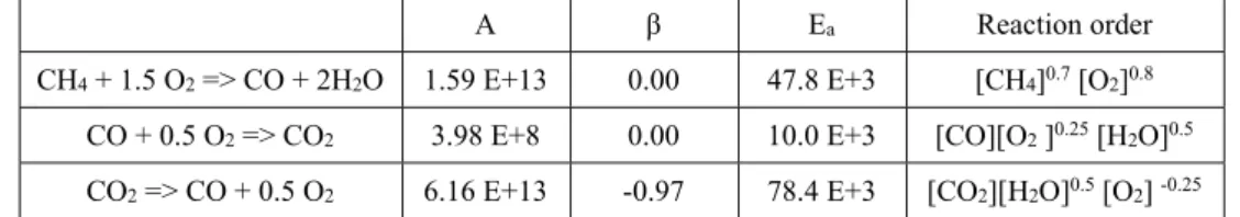
ECHANISMSTable 1 Modified Westbrook and Dryer global mechanism (Westbrook and Dryer, 1981). Units in cm, s, cal, mol. A is the pre-exponential factor, Ea is the activation energy, β is the temperature exponent
A β Ea Reaction order
CH4 + 1.5 O2 => CO + 2H2O 1.59 E+13 0.00 47.8 E+3 [CH4]0.7 [O2]0.8
CO + 0.5 O2 => CO2 3.98 E+8 0.00 10.0 E+3 [CO][O2 ]0.25 [H2O]0.5
CO2 => CO + 0.5 O2 6.16 E+13 -0.97 78.4 E+3 [CO2][H2O]0.5 [O2] -0.25
Table 2 Modified Jones and Lindstedt global mechanism (Jones and Lindstedt, 1988). Units in cm, s, cal, mol. A is the pre-exponential factor, Ea is the activation energy, β is the temperature exponent
A β Ea Reaction order
CH4 + 0.5 O2 => CO + 2 H2 7.82 E+13 0.00 30.0 E+3 [CH4]0.5 [O2]1.25
CH4 + H2O => CO + 3 H2 3.00 E+11 0.00 30.0 E+3 [CH4][H2O]
H2 + 0.5 O2 => H2O 5.0 E+20 -1.00 30.0 E+3 [H2]0.25 [O2]1.5
H2O => H2 + 0.5 O2 2.93 E+20 -0.877 97.9 E+3 [H2] -0.75[O2][H2O]
CO + H2O <=> CO2 + H2 2.75 E+12 0.00 20.0 E+3 [CO][H2O]
the in-flame CO peaks are dramatically higher in CO2 diluted conditions, remaining higher also in the post-flame region. The CO content is expected to convert further downstream at lower temperature, being CO favored at higher temperatures in the CO/CO2 equilibrium. It was demonstrated that the higher CO2 concentration in oxy-combustion is responsible, through the equilibrium reaction CO2+H↔CO+OH at high and medium temperature and through CO2 reactions with hydrocarbon radicals, of the increased emissions of carbon-monoxide. The subtraction of H radicals from the previous reaction inhibits the most important chain branching reaction O2+H→OH+O and slows down the overall burning rate.
In order to reduce the computational cost of CFD simulations, simplified reaction mechanisms are normally used with a limited number of chemical species and reactions. The most common reaction mechanisms are of the global type and comprise a small number of steps and species. They have generally been generated for air combustion and therefore have to be modified for oxy-combustion. Among them the most popular are the two steps mechanism of Westbrook and Dryer (WD) (1981) and four steps mechanism of Jones and Lindstedt (JL) (1998). Comparing the numerical results with respect to those obtained with a detailed mechanism, Andersen et al. (2009) in effect showed that in oxy-combustion conditions modifications of the global mechanisms are needed to improve accuracy. In fact both fail in predicting the ignition time and while the WD overestimates the final levels of CO, the JL behaves better in this regard, overestimating only the in-flame CO peaks. The time scale of fuel conversion was instead caught satisfactorily. In particular, the WD was modified by introducing the CO2 dissociation reaction and in the reaction constants (Table 1). The JL was modified only in the reactions constants (Table 2). It was thus possible to obtain CFD and plug-flow
reactor results more adherent to the experimental data. Yin et al. (2011) in the CFD simulations of a furnace fueled by natural gas under oxy-combustion conditions, successfully used the same WD modified by Andersen et al. (2009) and a modified version of the JL proposed by Kim et al. (2008). Wang et al. (2012) conducted plug-flow reactor and CFD analysis, using different versions of the WD and the JL and concluding that the results that well matched with the experimental data were obtained with the WD version of Andersen et al. with the addition of the H2 oxidation reaction proposed by Marinov et al. (1996).
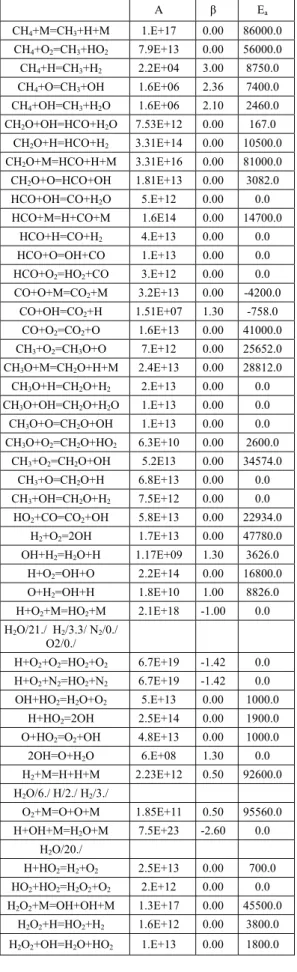
Table 3 Reduced mechanism (Smooke et al.
(1986)). Units in cm, s, cal, mol. A is the pre-exponential factor, Ea is the activation energy, β
is the temperature exponent
A β Ea
CH4+M=CH3+H+M 1.E+17 0.00 86000.0
CH4+O2=CH3+HO2 7.9E+13 0.00 56000.0
CH4+H=CH3+H2 2.2E+04 3.00 8750.0
CH4+O=CH3+OH 1.6E+06 2.36 7400.0
CH4+OH=CH3+H2O 1.6E+06 2.10 2460.0
CH2O+OH=HCO+H2O 7.53E+12 0.00 167.0
CH2O+H=HCO+H2 3.31E+14 0.00 10500.0
CH2O+M=HCO+H+M 3.31E+16 0.00 81000.0
CH2O+O=HCO+OH 1.81E+13 0.00 3082.0
HCO+OH=CO+H2O 5.E+12 0.00 0.0
HCO+M=H+CO+M 1.6E14 0.00 14700.0
HCO+H=CO+H2 4.E+13 0.00 0.0
HCO+O=OH+CO 1.E+13 0.00 0.0
HCO+O2=HO2+CO 3.E+12 0.00 0.0
CO+O+M=CO2+M 3.2E+13 0.00 -4200.0
CO+OH=CO2+H 1.51E+07 1.30 -758.0
CO+O2=CO2+O 1.6E+13 0.00 41000.0
CH3+O2=CH3O+O 7.E+12 0.00 25652.0
CH3O+M=CH2O+H+M 2.4E+13 0.00 28812.0
CH3O+H=CH2O+H2 2.E+13 0.00 0.0
CH3O+OH=CH2O+H2O 1.E+13 0.00 0.0
CH3O+O=CH2O+OH 1.E+13 0.00 0.0
CH3O+O2=CH2O+HO2 6.3E+10 0.00 2600.0
CH3+O2=CH2O+OH 5.2E13 0.00 34574.0
CH3+O=CH2O+H 6.8E+13 0.00 0.0
CH3+OH=CH2O+H2 7.5E+12 0.00 0.0
HO2+CO=CO2+OH 5.8E+13 0.00 22934.0
H2+O2=2OH 1.7E+13 0.00 47780.0
OH+H2=H2O+H 1.17E+09 1.30 3626.0
H+O2=OH+O 2.2E+14 0.00 16800.0
O+H2=OH+H 1.8E+10 1.00 8826.0
H+O2+M=HO2+M 2.1E+18 -1.00 0.0
H2O/21./ H2/3.3/ N2/0./
O2/0./
H+O2+O2=HO2+O2 6.7E+19 -1.42 0.0
H+O2+N2=HO2+N2 6.7E+19 -1.42 0.0
OH+HO2=H2O+O2 5.E+13 0.00 1000.0
H+HO2=2OH 2.5E+14 0.00 1900.0
O+HO2=O2+OH 4.8E+13 0.00 1000.0
2OH=O+H2O 6.E+08 1.30 0.0
H2+M=H+H+M 2.23E+12 0.50 92600.0
H2O/6./ H/2./ H2/3./
O2+M=O+O+M 1.85E+11 0.50 95560.0
H+OH+M=H2O+M 7.5E+23 -2.60 0.0
H2O/20./
H+HO2=H2+O2 2.5E+13 0.00 700.0
HO2+HO2=H2O2+O2 2.E+12 0.00 0.0
H2O2+M=OH+OH+M 1.3E+17 0.00 45500.0
H2O2+H=HO2+H2 1.6E+12 0.00 3800.0
H2O2+OH=H2O+HO2 1.E+13 0.00 1800.0
3.
B
URNERD
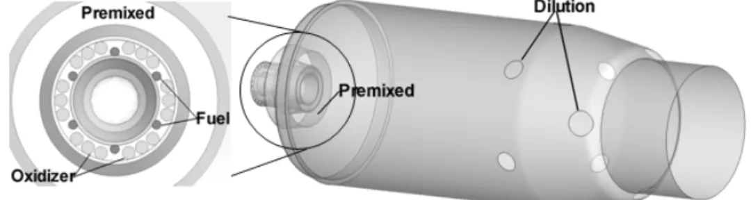
ESCRIPTIONThe 300 kW combustor analyzed (Fig. 2) is provided with a classical swirl premixed burner and an axial diffusion pilot flame. The oxidizer CO2/O2 flows opposite to the combustion products through the annulus formed between the case and the liner, helping to cool down the different components. A part mixes with fuel in the burner head forming the premixed ignitable mixture and supplies oxygen for the pilot, a part feeds the chamber dilution holes at the end of the chamber, helping to reduce temperatures at a sustainable level for the turbine blades. It also feeds several cooling slots along the liner which prevent materials overheating. The pilot burner is provided with six methane injectors. The combustion chamber is about 400 mm long and the diameter is about 150mm.
4. C
FDN
UMERICALM
ODELSGiven the lack of experimental data, a proper choice of the numerical models is crucial. An accurate literature review was then effectuated in order to identify the most appropriate turbulence and combustion models for the particular flow and combustion regime of the present case. The ANSYS-FLUENT™ software was used to solve all the governing equations. The software is based on the finite-volume method for the approximate solution of the partial differential equations. The SIMPLE pressure based segregated algorithm was adopted, which is appropriate for incompressible flow and calculates the pressure field from a pressure-correction equations obtained from continuity and momentum equations:
0 ) ( i i u x t
(4.1)
i j
j l l ij i j j i j i j i j i u u x x u x u x u x x p u u x t u ' ' 3 2 (4.2)
where u is the mean velocity, u' is the fluctuating velocity, p is the static pressure, µ is the molecular viscosity and ρ is the density.
A steady RANS approach was chosen for turbulence. Given the number of simulations to be performed the more computationally expensive LES approach was not feasible. In particular the two equations RNG k-ε model (Launder and Spalding, (1972), Yakhot and Orszag (1986)) was adopted.
Fig. 1. Species mole fraction profiles. Isothermal plug flow reactor, T=1600 K, φ=0.8, O2 20 %. Kinetic
mechanisms: upper left GB, upper right RD-SM, bottom left WD-mod, bottom right JL-mod.
Fig. 2. Burner and combustion chamber geometry with a detail of the burner head.
model for particular flow configurations. This model compared to the standard model presents some advantages regarding to the predictions accuracy for rotating and recirculating flows, that make this model suitable for swirling flows. Using the Boussisesq approach, the Reynolds stressed are:
j i k k t i j j i t j i x u k x u x u u u
3 2 ' ' (4.3)where k is the turbulent kinetic energy and µt is the turbulent viscosity. The k and ε equations are:
M b k j eff k j i i Y G G x k x ku x k t
) ( )( (4.4)
R k C G C G k C x x u x t b k j eff j i i 2 2 3 1 ) ( ) ( (4.5) where: 2 / ' 'iui u k (4.6) j i j i x u x u
' '
(4.7) i j j i k x u u u G
' ' (4.8) i t t i b x g G
µeff is the sum of molecular and turbulent viscosity,
Gk and Gb are the generation of turbulent kinetic energy due to the mean velocity gradients and buoyancy, YM is related to compressibility effects and gi is the gravitational component. C1ε=1.42
C2ε=1.68, C3εis calculated andexpresses how ε is influenced by buoyancy, αk and αε are the inverse Prandtl numbers for k and ε. The turbulent viscosity is calculated from the equation:
ˆ 1 ˆ ˆ 72 , 1 3 2 d C k d (4.10) where: 100 /
ˆ
eff C(4.11) For high Reynolds numbers it becomes:
2 k C t (4.12) where C=0.0845. The swirl effect is taken into account modifying the viscosity as follow:
t t0f s, ,k(4.13)
where t0 is the viscosity in absence of swirl, Ω is a characteristic swirl number and αs depends upon the swirl intensity.
The inverse of the effective Prandtl numbers αk and αεare calculated from:
eff
0.3679
0 6321 . 0
0 2,3929
3929 , 2 3929 , 1 3929 , 1 (4.14) with α0=1.0. The extra term for the ε equation is evaluated as: k C R 2 3 0 3 1 1 (4.15) η=Sk/ε, η0=4.38 β=0.012. S is the modulus of the mean rate-of-strain tensor:
j i j i S S S j i i j j i u u x u S 2 1 (4.16) The species equation is:
k j k j k j j k R x J Y u x Y
t
) ( ) ( (4.17)
where Yk is the species mass fraction,Jjk is the turbulent diffusive flux:
j k t t k k j x Y Sc D J (4.18)
here Sct is the turbulent Schmidt number, Dk the
molecular diffusion coefficient, Rk is the source term due to reactions.
The total energy E equations is:
ij eff r i j eff j i i S u x T k x p E u x E t ) ( (4.19)where T is the temperature, Sr is a source term accounting for reactions and radiation, τij is the stress tensor and keff the effective thermal conductivity:
k k ij i j j i eff eff ij x u x u x u 3 2 (4.20) eff p eff ck
(4.21)
4 / 1
2
k v
C
(4.22)
C =2.1377, and a to have a volume equal to *3. Reactions are assumed to proceed in a time scale:
2 / 1
v C
(4.23)
where C=0.4082 and the reaction zone is modeled as a perfectly stirred reactor, using the Arrhenius law. The source term Rk in the species equations is determined as:
k i
k Y Y
R
*
3 * *
2 *
1
(4.24)
where Yk* is the species mass fraction after reaction. For what concern radiation heat transfer, the method of spherical harmonics, also known as PN method, is based on the idea that the solution of the radiation heat transfer equation can be simplified by expressing the radiation intensity as a series of products of angular and spatial functions. The number of terms used in the expansion provides the order and the method name (P1, P3, etc.). The approximations of even orders are never used since it is known that the odd orders are more accurate than the following even order. In this way only one diffusion equation for the incident radiation has to be solved. The PN model is particularly suitable for modeling systems in which the radiation is emitted isotropically and for optically thick medium, as happens in combustion processes. The disadvantage of the method is that as the order N increases the improved accuracy is negligible while the mathematical complexity grows strongly. In FLUENT the P1 approximation (Chen (1964) and Siegel and Howell (1992)) is used, in which the first four terms of the expansion are retained. In this case the radiative heat flux becomes:
G C aq
s s
r
3 1
(4.25) where a is the absorption coefficient, G is the incident radiation, s is the scattering coefficient and
C is a coefficient related to anisotropic scattering. Defining:
as Cs
3
1
(4.26)
the qr equation becomes:
G
qr (4.27)
The G transport equation is:
4 4 0 G aG a
T (4.28)where is the Stefan-Boltzmann constant. Combining the previous equations:
4
4a T aG qr
(4.29)
which represents the source term in the energy equation. A model for the radiative properties, emissivity and adsorptivity, is also needed. In the WSGG model (Coppale and Vervisch (1983) and Smit et al. (1982)) the gas mixture is modeled as a mixture of ideal gray gases and the emissivity is the weighted sum of the emissivities of the single components. The temperature dependent weights and the absorption coefficients are obtained by fitting experimental data or data calculated with more sophisticated models.
All the governing equations were discretized with a second order upwind scheme. The molecular properties were calculated by means of the gas kinetic theory.
In absence of experimental data, the numerical models were validated on a oxy-fuel literature test case. The IFRF OXYFLAM project data (Lallemant et al. (1996)) were selected as benchmark, since in-furnace temperature and species profiles were measured. The water cooled 1050x1050x3440 furnace (named OXYFLAM2) is equipped with a 0.78 MW high momentum natural gas coaxial burner (named A). Further details can be found in Lallemant et al. (1996). As performed by other authors, in order to reduce the computational effort, the system was simulated using a 2D axy-symmetric mesh, with about 50000 cells. In Fig. 3 are reported the radial profiles at several distances from the burner. The agreement is good and in line with the results of simulations reported in other works. The accuracy of the predictions of the k-ε turbulence model and the EDC combustion model with reduced chemical mechanisms, for diluted combustion burner simulations, was already demonstrated by several authors (Rebola et al. (2013), Aminian et al. (2011), Frassoldati et al. (2010), Danon and Roekaerts (2010), De et al. (2010), Christo and Dally (2005)).
Given the complexity of the geometry, a tetrahedral mesh was generated around the domain boundaries, while the internal domain was meshed with hexahedral cells, in order to save computational resources. A sensitivity analysis was also conducted for what regard the mesh number of elements. Then progressively refined mesh were generated until no variations were registered in the results. The hybrid mesh consists of 1.230.000 cells.
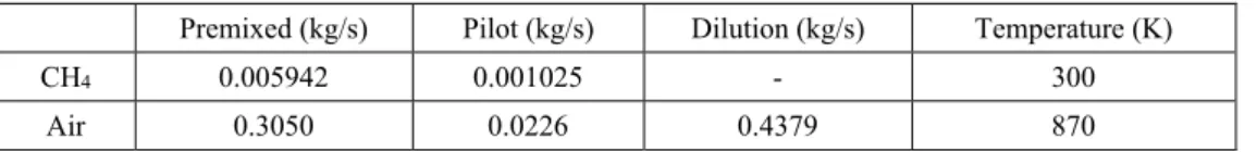
The mass flow rates for air-combustion reported in Table 4 were used as starting point for the oxy-combustion simulations. The oxidizer CO2/O2 flow-rate between the case and the liner was not simulated and the distribution of the CO2/O2 mixture between the premixed, the pilot and the dilution inlets was done on the basis of the data available for the air combustion case.
Fig. 3. Temperature and species radial profiles for the validation case. Experimental data: ▬
□
22mm,▬▬
Δ
82mm, ▪▪▪▪○
142mm from the burner. Calculated data: ▬22mm, ▬▬82mm, ▪▪▪▪142mm from the burner.Table 4 Reference conditions for air combustion
Premixed (kg/s) Pilot (kg/s) Dilution (kg/s) Temperature (K)
CH4 0.005942 0.001025 - 300
Air 0.3050 0.0226 0.4379 870
5. C
FDR
ESULTSThe simple substitution of N2 with CO2 (i.e. 21 % O2) led to flame extinction. This is because the higher CO2 heat capacity requires a higher oxygen concentration, with the consequent higher temperatures, for the flame to sustain. In a typical lean-premixed air combustion case, premixing and high dilution allow to contain temperatures and then to reduce the NOx formation, but in the oxy-combustion case this problem doesn't exist due to the absence of nitrogen. Even if it is not sufficient in concentration for flame sustainment, the overall oxygen amount is much higher with respect to the stoichiometric value, considering the portion of oxygen flowing throw the dilution holes, which is mostly wasted in the flue gases. That represents a cost, since oxygen has to be produced with the consequent energy consumption. Therefore, with the aim to reduce the total amount of oxygen consumed, for a fixed thermal power, i.e. a fuel flow-rate input, the CO2 flow-rate was gradually reduced by a factor R, with respect the reference air combustion case (Table 4). This allows a lower dilution in the premixed mixture through the
reduction of the CO2 flow rate, with the consequent compensation of the higher heat capacity and to enhance the oxygen concentration also with an overall lower mass flow rate of oxygen itself. This will finally results in a reduction of the oxygen level in the flue gases. With the aim to obtain a considerable abatement of the wasted oxygen, R was increased up to 3. For each R then oxygen was also gradually reduced until flame blow-out.
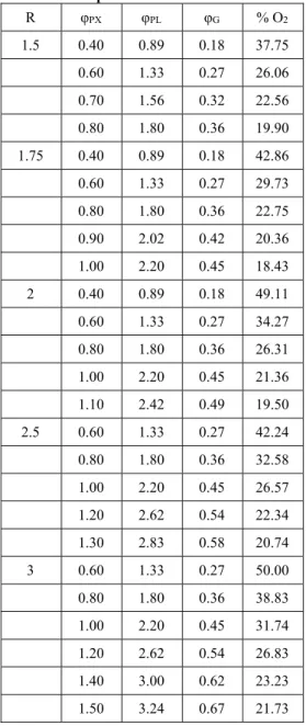
The complete test matrix is shown in Table 5, where φPX is the premixed equivalence ratio ((mCH4/mO2)/(mCH4/mO2)stoic), φPL is the pilot equivalence ratio, φG refers to the overall equivalence ratio and considers the oxygen flow through the dilution holes.
Table 5 Complete list of the simulated cases
R φPX φPL φG % O2
1.5 0.40 0.89 0.18 37.75
0.60 1.33 0.27 26.06
0.70 1.56 0.32 22.56
0.80 1.80 0.36 19.90
1.75 0.40 0.89 0.18 42.86
0.60 1.33 0.27 29.73
0.80 1.80 0.36 22.75
0.90 2.02 0.42 20.36
1.00 2.20 0.45 18.43
2 0.40 0.89 0.18 49.11
0.60 1.33 0.27 34.27
0.80 1.80 0.36 26.31
1.00 2.20 0.45 21.36
1.10 2.42 0.49 19.50
2.5 0.60 1.33 0.27 42.24
0.80 1.80 0.36 32.58
1.00 2.20 0.45 26.57
1.20 2.62 0.54 22.34
1.30 2.83 0.58 20.74
3 0.60 1.33 0.27 50.00
0.80 1.80 0.36 38.83
1.00 2.20 0.45 31.74
1.20 2.62 0.54 26.83
1.40 3.00 0.62 23.23
1.50 3.24 0.67 21.73
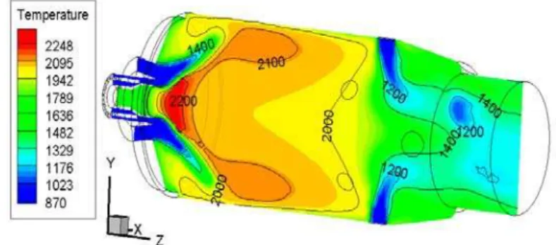
Further downstream it is evident the cooling action of the flow coming from the dilution holes. A proper distribution and diameter sizing of these holes along the liner, permit an adequate penetration into the main stream. This, together with the swirling effect of the premixed flow, allow a good mixing of the flue gases with the CO2/O2 mixture and a more uniform temperature field at the exit (Fig. 5). It is evident how the central zone of the exit section is the coldest one, while in the peripheral zone temperatures are higher.
There are many ways to achieve flames stabilization, but all the techniques are based on the formation of recirculation zones which produce the entrainment of the hot flue gases toward the fresh unburned mixture, causing ignition. For the main premixed flame the swirl effect causes the flow expansion toward the chamber walls and the formation of two counter-rotating vortices that extend up to the middle of the combustion chamber (Fig. 6). For the pilot flame the injection of fuel and
oxidizer through a series of circumferentially arranged holes respect to the burner axis, produces in fact some small vortices that help flame anchorage and stabilization (Fig. 7).
As can be seen from Table 5, there are some cases for which the oxygen flow-rate at the pilot inlet is lower than the stoichiometric value relative to the pilot fuel flow rate (φPL>1). For some of those cases the pilot flame become very weak until extinguishes as the oxygen mass flow is diminished. In order to determine the extinction conditions an analysis of the temperature along the burner axis is reported in the Fig. 8. It is clear how the initial pilot flame temperature peak reduces until it disappears. This always happens in the φPX =0.7-0.8 range and for values of φPL near 1.8.
For what concern the main flame, the CO2 flow reduction allows the combustion reaction to sustain for growing values of φPX. In Fig. 9 it's shown the dependence of the (φPX)bo, i.e. the φPX at the blow-out condition, as a function of R. There is an almost linear dependence between (φPX)bo and R. For sufficiently high value of R, (φPX)bo become greater than 1, which means that the main flame sustains also for fuel-rich under-stoichiometric initial conditions.
The combustion process completes thanks to by the oxygen in the dilution stream. It is interesting to note that if (φPX)bo increase with R, the oxygen concentration in the oxidizer related to (φPX)bo is always about 20 %. So there must be a minimum O2 concentration in the premixed, near the value 20 %, for the main flame sustainment. The Fig. 10 shows the O2 flow rate at the burner exit. It is obvious that if R increases and the flame sustains for increasing values of φPX and φG, the amount of unconsumed O2 at the exit reduces. Clearly the minimum level of oxygen is obtained for R=3. In this situation the minimum value of φPX for a sustained flame is about 1.4 ((φPX)bo=1.5), which correspond to a φG of 0.62 and the O2 concentration at the burner exit is about 10%.
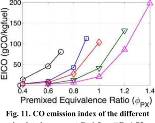
The burner efficiency for the studied cases can be evaluated by means of the analysis of the unburned species at the exit and the heat release compared to the thermal input. In Fig. 11 it's reported the CO flow rate at the exit, that is the main component of the unburned and of the pollutant species, related to the fuel flow rate. From the figure it can be seen that for each value of R, the increase of φPX causes the emission index EICO to increase due to the lower oxygen concentration in the oxidizer flow.It must be reminded that for φPX>1, since φG is always less than one, the necessary oxygen to the combustion process completion is available from the dilution flow. However the dilution flow produces a rapid hot gases cooling and then inhibits the combustion reactions and the CO→CO2 complete conversion. On the other hand the reduction of the CO2 flow causes higher temperature which are favorable to complete combustion. That leads to an improvement of the combustion efficiency which generally tends to increases with R and decreases with the increase of
Fig. 4. Temperature contours (K) on a longitudinal plane section. R=2, φPX=0.6.
Fig. 5. Temperature (K) and OH mass fraction contours. R=2, φPX=0.6. The dashed lines represent the
main flame zone of intense reaction (iso-lines of OH mass fraction). The iso-surface (constant temperature of 2200 K) represents the pilot flame.
Fig. 6. Path lines and velocity contours (m/s) on a longitudinal plane section. R=2, φPX=0.6.
Fig. 7. Vectors plot zoomed around the pilot burner. R=2, φPX=0.6. The continuous ellipsoidal
lines highlight the stabilizing vortices structures of the pilot flame.
Fig. 9. Premixed and the corresponding global equivalence ratio of the main flame blow-out for
the different simulated cases.
Fig. 10. Unconsumed O2 in the exhaust gases of
the different simulated cases.
Fig. 11. CO emission index of the different simulated cases. ▬O R=1.5, ▬□R=1.75,
▬◇R=2, ▬▽R=2.5, ▬
△
R=3.Commercial GT burners are very similar to the one analyzed here and from the showed results it's possible to asses that these burners, designed for classic air combustion, cannot work in an optimal way in oxy-combustion conditions without modifications. One possible solution could be the increase of the burner length and the increase of the dilution holes number along the liner in order to have a more gradual CO2/O2 supply with a slower cooling effect. Another possible solution could be the re-design of the premixing system in a way that allows the oxygen enrichment of the recirculated CO2 flow directly at the burner head. In this way only a CO2 flow would enter initially the entire device and would distribute among the pilot, the main burner and only CO2 would be injected
through the dilution holes, with a minimal consumption of oxygen.
Fig. 12. Combustion efficiency of the different simulated cases. ▬O R=1.5, ▬
□
R=1.75, ▬◇R=2, ▬▽R=2.5, ▬
△
R=3.5. C
ONCLUSIONSBy means of CFD simulations a commercial micro gas turbine burner, originally designed for air combustion, was tested in oxy-combustion conditions. The simple replacement of the N2 content with CO2 has led to flame blow-out. An increase of the oxygen content in the oxidizer flow over 21 % was then indispensable in this case so that the higher flame temperature can balance the higher heat capacity. In order to compensate the increased heat capacity and to reduce the residual oxygen content in the flue gases, a progressive reduction of the CO2 mass flow rate was effectuated with the aim to identify the minimum oxygen content necessary for the flame sustainment.
As expected, as CO2 decrease the minimum oxygen content can be decreased, even though the oxygen supply to the pilot burner is insufficient for the pilot flame to ignite. For R≥2 the equivalence ratio of the main premixed flame φPX can be bigger than 1, which means that the flame is able to sustain in fuel rich conditions or in other words with less oxygen with respect to the necessary stoichiometric amount. The combustion reactions however proceed thanks to the oxygen content in the dilution flow. In these conditions however the burner performances become of poor quality. In fact the unburned content in the exhaust gases rises rapidly while the thermal efficiency drops. Modifications of the geometry are in conclusion needed so that the burner can be employed efficiently in oxy-combustion conditions.
R
EFERENCESAmato, A., B. Hudak, P. D'Carlo, D. Noble, D. Scarborough, J. Seitzman and T. Lieuwen (2011). Methane oxycombustion for low CO2 cycles: blowoff measurement and analisys. Journal of Engineering for Gas Turbines and Power 133(6).
Tognotti (2012). Numerical investigation of a MILD combustion burner: analysis of mixing field, chemical kinetics and turbulence-chemistry interaction. Flow Turbulence Combust 88, 597–623.
Andersen, J., C. L. Rasmussen, T. Giselsson and P. Glarborg (2009). Global combustion mechanisms for use in CFD modelling under oxy-fuel conditions. Energy and Fuels 23(3), 1379-1389.
Cheng, P. (1964). Two-dimensional radiating gas flow by a moment method. AIAA Journal 2, 1662-1664.
Christo, F. C. and B. B. Dally (2005). Modeling turbulent reacting jets issuing into a hot and diluted coflow. Combust. Flame 142, 117-129. Coppalle, A. and P. Vervisch (1983). The total
emissivities of high-temperature flames. Combust. Flame 49, 101-108.
Danon, B., W. De Jong and D. Roekaerts (2010). Experimental and numerical investigation of a FLOX combustor firing low calorific value gases. Combust. Sci. Technol. 182(9), 1261– 1278.
De, A., E. Oldenhof, P. Sathiah and D. Roekaerts (2011). Numerical simulation of delft-jet-in-hot-coflow (DJHC) flames using the eddy dissipation concept model for turbulence– chemistry interaction. Flow Turbulence Combust 87, 537–567.
Ditaranto, M. and J. Hals (2006). Combustion instabilities in sudden expansion oxy-fuel flames. Combustion and Flame 146, 493–512. Frassoldati, A., P. Sharma, A. Cuoci, T., Faravelli
and E. Ranzi (2010). Kinetic and fluid dynamics modeling of methane/hydrogen jet flames in diluted coflow. Appl. Therm. Eng. 30, 376–383.
Glarborg, P. and L. L. B. Bentzen (2007). Chemical effects of a high CO2 concentration in oxy-fuel combustion of methane. Energy and Fuels 22, 291–296.
Gran, I. R. and B. F. Magnussen (1996). A numerical study of a bluff-body stabilized diffusion flame. part 2. influence of combustion modeling and finite-rate chemistry. Combustion Science and Technology 119, 191-217.
Heil, P., D. Toporov, M. Förster and R. Kneer (2011). Experimental investigation on the effect of O2 and CO2 on burning rates during oxyfuel combustion of methane. In Proceedings of the Combustion Institute 33, 3407–3413.
Jones, W. P. and R. P. Lindstedt (1988). Global reaction schemes for hydrocarbon combustion. Combust. Flame 73, 233-249.
Kim, J. P., U. Schnell and G. Scheffknecht (2008). Comparison of different global reaction
mechanisms for mild combustion of natural gas. Combust Sci. Technol. 180, 565–92. Kutne, P., B. K. Kapadia, W. Meier and M. Aigner
M. (2011). Experimental analysis of the combustion behaviour of oxyfuel flames in a gas turbine model combustor. In Proceedings of the Combustion Institute 33, 3383–3390. Lallemant, N., J. Dugué and R. Weber (1996). IFRF
Document F85/y/4.
Launder, B. E. and D. B. Spalding (1972). Lectures in Mathematical Models of Turbulence. Academic Press, London, England.
Liu, C. Y., G., Chen, N. Sipöcz, M. Assadi and X. S. Bai (2012). Characteristics of oxy-fuel combustion in gas turbines. Applied Energy 89, 387-394
Liu, F., H. Guo and G. J. Smallwood (2003). The chemical effect of CO2 replacement of N2 in air on the burning velocity of CH4 and H2 premixed flames. Combustion and Flame 133, 495-497.
Magnussen, B. F. (1981). On the structure of turbulence and a generalized eddy dissipation concept for chemical reaction in turbulent flow. In proceeding of Nineteeth AIAA Meeting, St. Louis.
Marinov, N. M., C. K. Westbrook and W. J. Pitz (1996). Detailed and global chemical kinetics model for hydrogen. In: Chan SH, editor. Transport phenomena in combustion. Washington, DC: Taylor and Francis.
Nemitallah, M. A. and M. A. Habib (2013). Experimental and numerical investigations of an atmospheric diffusion oxy-combustion flame in a gas turbine model combustor. Applied Energy 111, 401-415.
Oh, J. and D. Noh (2014). The effect of CO2 addition on the flame behavior of a non-premixed oxy-methane jet in a lab-scale furnace. Fuel 117, 79-86.
Pope, S. B. (1997). Computationally efficient implementation of combustion chemistry using in-situ adaptive tabulation. Combustion Theory and Modeling 1, 41-63.
Rebola, A., P. J. Coelho and M. Costa (2013). Assessment of the performance of several turbulence and combustion models in the numerical simulation of a flameless combustor. Combustion Science and Technology 185(4), 600-626.
Seepana, S. and S. Jayanti (2012). Experimental studies of flame extinction in a swirl-stabilized oxy-fuel burner. Fuel 93, 75–81.
Siegel, R. and J. R. Howell (1992). Thermal Radiation Heat Transfer. Hemisphere Publishing Corporation, Washington DC.
sum of gray gases model. J. Heat Transfer 104, 602-608.
Smooke, M. D., I. K. Puri and K. Seshadri (1986). A comparison between numerical calculations and experimental measurements of the structure of a counterflow diffusion flame burning diluted methane in diluted air. Proceedings of the Combustion Institute 21, 1783-1792.
Wang, L., Z. Liu, S. Chen and Z. Chuguang (2012). Comparison of different global combustion mechanisms under hot and diluted oxidation conditions. Combust. Sci. Technol. 184, 1-18. Westbrook, C. K. and F. L. Dryer (1981).
Simplified reaction mechanisms for the
oxidation of hydrocarbon. Combust. Sci. Technol. 27, 31-44.
Xie, Y., J. Wang, M. Zhang, J. Gong, W. Jin and Z. Huang (2013). Experimental and numerical study on laminar flame characteristics of methane oxy-fuel mixtures highly diluted with CO2. Energy Fuels 27, 6231−6237.
Yakhot, V. and S. A. Orszag (1986). Renormalization group analysis of turbulence: I. Basic theory. Journal of Scientific Computing 1(1), 1-51.