UNIVERSIDADE NOVA DE LISBOA
Faculdade de Ciˆ
encias e Tecnologia
Departamento de Engenharia Electrot´ecnica e de Computadores
Supporting NAT Traversal
and Secure Communications in a
Protocol Implementation Framework
Por:
Pedro Arruda Pereira
Disserta¸c˜ao apresentada na Faculdade de Ciˆencias e Tecnologia
da Universidade Nova de Lisboa para obten¸c˜ao do Grau
de Mestre em Engenharia Electrot´ecnica e de Computadores.
Orientador: Prof. Doutor Paulo da Costa Lu´ıs Fonseca Pinto
Protocol Implementation Framework
Copyright c 2011 por Pedro Arruda Pereira, Faculdade de Ciˆencias e Tecnologia e Universidade Nova de Lisboa.
A Faculdade de Ciˆencias e Tecnologia e a Universidade Nova de Lisboa tˆem o direito,
perp´etuo e sem limites geogr´aficos, de arquivar e publicar esta disserta¸c˜ao atrav´es de
ex-emplares impressos reproduzidos em papel ou de forma digital, ou por qualquer outro meio
conhecido ou que venha a ser inventado, e de a divulgar atrav´es de reposit´orios cient´ıficos
e de admitir a sua c´opia e distribui¸c˜ao com objectivos educacionais ou de investiga¸c˜ao,
Preface
I would like to thank all those who in some way contributed and supported me during the
completion of my degree and this dissertation.
To Prof. Paulo Pinto, for giving me the honour of his advice, the availability and patience
to answer all my questions and the assertive guidance towards the completion of this
dissertation. It was very kind of him to accept being my supervisor under my exchange
studies period.
To Prof. Jarmo Harju for believing in my capabilities and giving me the opportunity
to work in the communications research group and for supporting with all the technical
material needed. I am very grateful for the support.
To Researcher Bilhanan Silverajan for the valuable help during the development of this
thesis. I would like to thank him for the patience in all this learning process and for all
the hours spent helping and guiding me towards the completion of this dissertation.
In my office at the Department of Communications Engineering at TUT I was surrounded
by knowledgeable and friendly people who helped me daily. I would like to express my
gratitude to my office mates Jani Peltotalo and Joona Kannisto for being so nice and
helpful.
To all my Portuguese friends in Finland especially Luis Sousa and Alberto Miranda who
treated me as family and supported me from very closely.
I would like to thank all of my colleagues and close friends from FCT-UNL that gave me
support since the beginning of my studies: Tiago Gaspar, F´abio Silva, Bruno Alves, Pedro
Neves, David Gon¸calves, Filipe Correia, Jo˜ao Melo and Diogo Figueiredo.
I would like to show the most kind and special gratitude to my family especially my
parents Armando and Concei¸c˜ao, as well as my brother Ricardo, and my grandmother
Maria Teresa, who have been a constant source of support during my graduation years
and have always supported me during the most difficult times of my life. This thesis would
certainly not have existed without them.
Last but not least, a special gratitude goes to my beloved girlfriend Emma for her
pa-tience, understanding and support, who shared time towards the completion of this thesis,
and who always trusted in my abilities and encouraged me to follow my dreams without
Abstract
The DOORS framework is a versatile, lightweight message-based framework developed in
ANSI C++. It builds upon research experience and subsequent knowledge garnered from
the use and development of CVOPS and OVOPS, two well known protocol development
frameworks that have obtained widespread acceptance and use in both the Finnish industry
and academia. It conceptually resides between the operating system and the application,
and provides a uniform development environment shielding the developer from operating
system specific issues. It can be used for developing network services, ranging from simple
socket-based systems, to protocol implementations, to CORBA-based applications and
object-based gateways.
Originally, DOORS was conceived as a natural extension from the OVOPS framework to
support generic event-based, distributed and client-server network applications. However,
DOORS since then has evolved as a platform-level middleware solution for researching the
provision of converged services to both packet-based and telecommunications networks,
enterprise-level integration and interoperability in future networks, as well as studying
application development, multi-casting and service discovery protocols in heterogeneous
IPv6 networks.
In this thesis, two aspects of development work with DOORS take place. The first is
the investigation of the Network Address Translation (NAT) traversal problem to give
support to applications in the DOORS framework that are residing in private IP networks
to interwork with those in public IP networks. For this matter this first part focuses on
the development of a client in the DOORS framework for the Session Traversal Utilities
for NAT (STUN) protocol, to be used for IP communications behind a NAT. The second
aspect involves secure communications. Application protocols in communication networks
are easily intercepted and need security in various layers. For this matter the second part
focuses on the investigation and development of a technique in the DOORS framework
to support theTransport Layer Security (TLS) protocol, giving the ability to application
protocols to rely on secure transport layer services.
Keywords: DOORS, framework, NAT, NAT traversal, STUN, security, secure
Resumo
DOORS ´e um framework vers´atil e baseado em mensagens que foi desenvolvido em C++.
´
E fruto da experiˆencia de investiga¸c˜ao e conhecimento obtida pelas plataformas de
de-senvolvimento CVOPS e OVOPS. Estas plataformas tˆem sido bastante aceites tanto na
ind´ustria como no campo de investiga¸c˜ao Finlandesa. O DOORS reside entre o sistema
operativo e a aplica¸c˜ao, fornecendo um ambiente de desenvolvimento uniforme protegendo
o programador de quest˜oes espec´ıficas do sistema operativo. Pode ser usado tanto para o
desenvolvimento de servi¸cos de rede, que v˜ao desde sistemas simples com sockets,
imple-menta¸c˜ao de protocolos, como para aplica¸c˜oes baseadas em CORBA e gateways baseados
em objectos.
Originalmente o DOORS foi concebido como uma extens˜ao natural da plataforma OVOPS
para suportar aplica¸c˜oes de redes gen´ericas baseadas em eventos, distribu´ıdas e
cliente-servidor. No entanto, desde ent˜ao, o DOORS tem evolu´ıdo como uma solu¸c˜ao de
mid-dleware para investigar a presta¸c˜ao de servi¸cos convergentes para as redes de pacotes e
de telecomunica¸c˜oes, para a integra¸c˜ao a n´ıvel empresarial e de interoperabilidade em
re-des futuras. Tamb´em se pretende que sirva para estudar o re-desenvolvimento de aplica¸c˜oes
multi-casting e protocolos de descoberta de servi¸cos em redes heterog´eneas IPv6.
Esta tese cobre dois aspectos de desenvolvimento no framework DOORS. O primeiro ´e a
investiga¸c˜ao do problema da penetra¸c˜ao em routersNetwork Address Translation (NAT),
de modo a dar-se suporte `as aplica¸c˜oes de redes IP privadas (para que possam interagir
com as redes IP p´ublicas). Para tal, desenvolveu-se um cliente no framework DOORS que
suporta o protocoloSession Traversal Utilities for NAT (STUN), que pode ser utilizado
para comunica¸c˜oes IP com m´aquinas protegidas por um NAT. O segundo aspecto envolve
comunica¸c˜oes seguras. Protocolos de aplica¸c˜ao em redes de comunica¸c˜ao s˜ao facilmente
interceptados e precisam de seguran¸ca em v´arias camadas. Nesta segunda parte
investigou-se e deinvestigou-senvolveu-investigou-se uma t´ecnica para suportar o protocoloTransport Layer Security (TLS)
no framework DOORS, permitindo que os protocolos de aplica¸c˜ao usem seguran¸ca na
camada de transporte.
Palavras-chave: DOORS, framework, NAT, penetra¸c˜ao em NATs, STUN,
Contents
Preface iii
Abstract v
Resumo vii
List of Acronyms xiii
List of Figures xviii
List of Tables xix
1 Introduction 1
1.1 Problem Statement and Motivation . . . 1
1.2 Objectives and Contributions . . . 2
1.3 Thesis Outline . . . 3
2 The DOORS Framework 5 2.1 Introduction . . . 5
2.2 Requirements . . . 5
2.3 Framework Architecture . . . 6
2.3.1 Scheduler . . . 9
2.3.2 I/O Handler and devices . . . 10
2.3.3 Tasks, Messages and Ports . . . 10
2.3.4 XML code generators . . . 11
2.3.5 Local Event Monitor (LEMon) . . . 12
3 Network Address Translation (NAT) 13 3.1 Introduction . . . 13
3.2 NAT Traversal . . . 15
3.3 Session Traversal Utilities for NAT (STUN) . . . 16
3.3.1 Protocol analysis . . . 16
3.3.2 Protocol operation . . . 18
3.3.3 STUN Message Structure . . . 20
3.3.4 STUN attributes . . . 22
4 Network Security 27 4.1 Introduction . . . 27
4.2 Approaches to Network Security . . . 28
4.3 Security Attacks . . . 31
4.3.1 Passive Attacks . . . 33
4.3.2 Active Attacks . . . 34
4.4 Security Services . . . 36
4.5 Cryptography . . . 37
4.5.1 Symmetric Encryption . . . 38
4.5.2 Public Key Encryption . . . 43
4.5.3 Hash Functions . . . 49
4.5.4 Digital Signatures . . . 49
4.5.5 Message Authentication Code . . . 50
4.5.6 Certificates . . . 51
4.6 Transport Layer Security (TLS) . . . 52
4.6.1 Introduction . . . 52
4.6.2 SSL/TLS Architecture . . . 53
4.6.3 Candidate Technologies . . . 60
5 Protocols’ Implementation 63 5.1 STUN Protocol . . . 64
5.1.1 Considerations and Choices . . . 64
5.1.2 Design Prototyping . . . 65
5.1.3 Design Architecture . . . 67
5.1.4 Modular Interaction and Behaviour . . . 68
5.1.5 Implementation . . . 72
5.2 TLS Protocol . . . 75
5.2.1 Considerations and Choices . . . 75
5.2.2 Design Overview . . . 77
5.2.3 Modular Interaction and Behaviour . . . 79
5.2.4 Implementation . . . 81
5.3 Development Environment . . . 84
6 Implementation Testing and Analysis 87 6.1 Test Network . . . 88
6.2 STUN Analysis . . . 89
6.2.1 Test Case . . . 89
CONTENTS xi
6.3 TLS Testing . . . 91
6.3.1 Test Case . . . 91
6.3.2 Results . . . 94
7 Conclusions 97 7.1 Synthesis . . . 97
7.2 Conclusions . . . 98
7.3 Future Work . . . 99
A Appendixes to the STUN Implementation 101 A.1 XML Specifications . . . 101
A.1.1 Peer/PDU Specifications . . . 101
A.1.2 State Machine Specifications . . . 103
A.1.3 Service Access Point Specifications . . . 104
A.2 StunTask Class Code . . . 105
B Appendixes to the TLS Implementation 107 B.1 XML Specifications . . . 107
B.1.1 State Machine Specifications . . . 107
B.1.2 Service Access Point Specifications . . . 108
B.2 TlsTask Class Code . . . 109
B.3 TlsConn Class Code . . . 110
List of Acronyms
AES Advanced Encryption Standard
ANSI American National Standards Institute
API Application Programming Interface
CBC CipherBlock Chaining
CFB Cipher FeedBack
DES Data Encryption Standard
DH Diffie-Hellman
DH anon Anonymous Diffie-Hellman
DHCP Dynamic Host Configuration Protocol
DHE Ephemeral Diffie-Hellman
DOORS Distributed Object OpeRationS
DoS Denial of Service
DDoS Distributed Denial of Service
DTLS Datagram Transport Layer Security
ECB Electronic Code Book
ECC Elliptic Curve Cryptography
ECDHE Elliptic curve Diffie-Hellman
FTP File Transfer Protocol
FSM Finite-State Machine
GCM Galois/Counter Mode
GNU GNU’s Not Unix
HMAC Hash-based Message Authentication Code
HTTP Hypertext Transfer Protocol
ICE Interactive Connectivity Establishment
IDEA International Data Encryption Algorithm
IEEE Institute of Electrical and Electronics Engineers
IETF Internet Engineering Task Force
IKE Internet Key Exchange
IP Internet Protocol
IPsec Internet Protocol Security
IPv4 Internet Protocol version 4
IPv6 Internet Protocol version 6
ISP Internet Service Provider
LAN Local Area Network
L2TP Layer 2 Tunneling Protocol
MAC Media Access Control
Message Authentication Code
NAT Network Address Translation
NIST National Institute of Standards and Technology
NSA National Security Agency
OFB Output FeedBack
P2P Peer to Peer
PDU Protocol Data Unit
PGP Pretty Good Privacy
PKI Public Key Infrastructure
PPTP Point-to-Point Tunneling Protocol
RC Rivest Cipher
RFC Request for Comments
SAP Service Access Point
SDU Service Data Unit
SHA Secure Hash Algorithm
SHS Secure Hash Standard
CONTENTS xv
SIP Session Initiation Protocol
SSL Secure Socket Layer
STL Standard Template Library
STUN Session Traversal Utilities for NAT
TCP Transmission Control Protocol
TLS Transport Layer Security
TUT Tampere University of Technology
UDP User Datagram Protocol
VoIP Voice over IP
VPN Virtual Private Network
XML Extensible Markup Language
WAN Wide Area Network
WCDMA Wideband Code Division Multiple Access
WEP Wired Equivalent Privacy
WiMAX Worldwide Interoperability for Microwave Access
WLAN Wireless Local Area Network
List of Figures
2.1 DOORS architecture . . . 7
2.2 DOORS communication model . . . 8
2.3 Examples of some of the DOORS classes . . . 9
2.4 Sending and asynchronous message in DOORS . . . 11
2.5 PDU definiton example . . . 12
3.1 Network address translation . . . 14
3.2 Possible STUN configuration . . . 17
3.3 Use STUN to find external IP/Port . . . 18
3.4 STUN Client-Server diagram . . . 19
3.5 Format of STUN message header . . . 21
3.6 Format of STUN Message Type field . . . 21
3.7 Format of STUN Attributes . . . 22
3.8 Format of XOR-Mapped-Address Attribute . . . 23
3.9 Format of Error-Code Attribute . . . 24
3.10 Format of Unknown-Attributes Attribute . . . 25
4.1 The Internet security protocols in the TCP/IP stack . . . 29
4.2 Security Threats . . . 32
4.3 Passive and Active Security attacks . . . 33
4.4 Working principle of a symmetric encryption system . . . 38
4.5 Public Key Cryptography . . . 44
4.6 Hierarchy of Thrust . . . 52
4.7 The SSL with its sub-layers and sub-protocols . . . 54
4.8 SSL Protocol Stack . . . 54
4.9 SSL/TLS Record Protocol operation . . . 55
4.10 SSL/TLS Record format . . . 56
4.11 SSL/TLS Handshake Protocol . . . 57
4.12 Simplied SSL/TLS Handshake Protocol (Resuming Session) . . . 58
5.1 Architecture overview of STUN support in DORRS . . . 66
5.2 STUN Task support in DOORS . . . 67
5.3 The message sequence diagrams for the Stun Task . . . 69
5.4 A STUN Requestmessage . . . 70
5.5 A STUN SuccessfulResponsemessage . . . 71
5.6 A STUN ErrorResponsemessage . . . 71
5.7 The state machine for the Stun Task . . . 72
5.8 Stun Implementation . . . 73
5.9 Architecture overview of TLS support in DORRS . . . 78
5.10 The state machine for the TlsTask . . . 80
6.1 Test Network . . . 88
6.2 Test STUN . . . 89
6.3 A partial capture of the LEMon User output during the STUN test . . . 90
6.4 A partial screen capture of Wireshark, during the STUN test . . . 90
6.5 Graph Analysis of Wireshark, during the STUN test . . . 90
6.6 Test TLS model . . . 92
6.7 Test HTTP over TLS . . . 93
6.8 A partial capture of a Connection Request in the LEMon user during the TLS test . . . 94
6.9 A partial capture of a Dtreq and Dtind in the LEMon user during the TLS test . . . 95
List of Tables
4.1 The three official versions of AES. . . 41
4.2 Applications for Public-Key Cryptosystems. . . 45
4.3 Content of an X.509 v3 Certificate. . . 51
4.4 Handshake Protocol Message Types. . . 58
4.5 Candidates’ Protocol Support. . . 61
4.6 Candidates’ Key Exchange Algorithms. . . 61
4.7 Candidates’ Encryption Algorithms. . . 61
4.8 Candidates’ Portability Concerns. . . 62
5.1 TlsConn states . . . 80
5.2 Tools used for Implementation . . . 85
5.3 Libraries used for Implementation . . . 85
Chapter 1
Introduction
1.1
Problem Statement and Motivation
The rapid development of computers and communications technology is allowing more and
more devices to interact with each other. One of the most profound changes today is the
increase in mobility of portable yet powerful wireless devices capable of communicating via
several different kinds of wireless radio networks of varying link-level characteristics. Such
wireless networks include 802.11-based Wi-Fi Local Area Networks (LANs), Wideband
Code Division Multiple Access (WCDMA) cellular networks, and Bluetooth or Infrared
based short range communications. Low-power energy efficient radio networks such as
ZigBee are widely expected to play dominant roles in the medium to long-term future
wireless mobility.
Accordingly to Silverajan [1], such increase of mobile networks raises the importance of
taking into account the resilience and sustainability of the Internet of the future, and give
special effort on the way applications and protocols today are being designed. Designing
applications and protocols in the future requires a clean layered design while raising the
level of abstraction to represent multiple applications in a device, multiple devices for a
user and multiple users in a network.
Taking into account these needs,Distributed Object OpeRationS (DOORS) [2] is presented
as a highly interoperable and lightweight event-based framework capable of serving these
needs while modelling, monitoring and handling events intrinsically present in
commu-nication architectures. Technically, DOORS is a C++ network programming framework
developed for implementing protocols and network applications. The framework can also
be used for developing network services, ranging from simple socket-based systems, to
dis-tributed applications, object-based gateways as well as general event-based client-server
applications.
Therefore, developing protocols at the network and application layers must also be
consid-ered. In this thesis, two different aspects are discussed. The first is the investigation of the
Network Address Translation (NAT) traversal problem to give support to applications in
the DOORS framework that are residing in private IP networks to interwork with others
in public IP networks. For this matter this first part focuses on developing client support
in the DOORS framework for the Session Traversal Utilities for NAT (STUN) [3]
proto-col, to be used for IP communications behind a NAT. The second aspect involves secure
communications. Application protocols in communication networks are easily intercepted
and might need security in various layers. For this matter the second part focuses on the
investigation and development of a technique in the DOORS framework to support the
Transport Layer Security (TLS) [4] protocol, giving the ability to application protocols to
rely on secure transport layer services.
1.2
Objectives and Contributions
This thesis focuses on two different aspects, both important for developing protocols in
the DOORS framework.
The first aspect focuses on NAT traversal solutions. The presented solution is the
imple-mentation of the STUN protocol in the DOORS framework, a tool to be used for other
protocols in the context of NAT traversal solutions.
The second aspect focuses on security in the network. Many applications interworking in
a public network might need a security layer in order to ensure a secure communication.
1.3. THESIS OUTLINE 3
and give support to applications in the DOORS framework that need to ensure secure
transactions. The presented solution is the integration of the TLS protocol in the DOORS
framework, a protocol to be combined with other application protocols that might need
to provide communication security over the Internet.
The main contributions of this dissertation are the implementations themselves, that are
fully integrated in the DOORS framework and can be used in the future by other
devel-opers. The proposed models are meant to be easy to use and to be integrated with other
protocols. The implementations are tested in order to study their operation and their
interoperability.
1.3
Thesis Outline
The thesis is structured in seven chapters, including the introduction and the conclusions
chapter.
Chapter 2 introduces a brief state-of-the-art description of the DOORS framework. It
presents its architecture and some of its functionalities.
Chapter 3 introduces a brief state-of-the-art description for NAT. It presents the usage of
NAT and the problems of its usage. Later on, it presents a useful protocol (STUN), a tool
to provide NAT traversal solutions.
Chapter 4 introduces a brief state-of-the-art description for Security in the Network. It
starts by presenting the most typical problems in different layers of a network, and later
on presents useful solutions to provide security. Lastly, it presents the TLS protocol, that
combines all the algorithms explained before to provide a sense of security for the problems
described before.
Chapter 5 adds some considerations and introduces the design of models and the
imple-mentation for the following two protocols: STUN and TLS.
Chapter 6 shows the results and presents the analysis and validation of the proposed
Finally, chapter 7 presents the final conclusions and remarks of this thesis, as well as some
future work perspectives.
Appendix A presents some technical information for the STUN implementation, and
Chapter 2
The DOORS Framework
2.1
Introduction
Distributed Object OpeRationS (DOORS) [1] is an object-based software framework for
designing distributed systems in heterogeneous network environments, especially on the
Internet. It is a C++ network programming framework developed for implementing
proto-cols and network applications. It gives the possibility to the programmer to write callback
functions and invoke them by the event handlers. Besides, the framework gives a platform
to the programmer and all the user events are mapped into DOORS messages. In terms
of portability, DOORS is both portable and lightweight. The developer is not hindered
from exercising any of the advanced C++ language-level features such as templates and
exception handling, nor is prevented from using other frameworks and other libraries as
part of the developed application. The DOORS is a single-threaded framework that can
be compiled and used in the most of UNIX and Linux variants [5].
2.2
Requirements
Since DOORS is written inAmerican National Standards Institute(ANSI) C++ language,
first it requires an ANSI-compliant compiler supporting features of the language
includ-ingStandard Template Library (STL), namespaces and template programming. Usually,
development platforms such as Solaris, FreeBSD, OpenBSD and Linux use GNU C++
compiler version 2.95.2 or later. Sun C++ compiler version 5 and later are used on Solaris
version 8 and 9 operating systems.
The operating system must also support many functions that are typically used in UNIX
systems such as pipe(), select(),malloc() and socket(). It must also support UNIX style
tty devices.
DOORS makes use of GNUautoconf andautomake to determine the current compilation
environment in use. They are used during the build phase to create and configure a UNIX
shell script which is then included in the released versions of DOORS and used in the
target system to make several tests on the system. These tests consist of checking if the
required C or C++ header files are available, compiling various C source files to discover
characteristics of the compiler in use and to verify that the required external libraries exist
in the system. After a successful check, the configure script createsMakefile files that are
used by make command to build the DOORS system by calling the compiler with each
source file and finally linking them to one library or an executable application [6].
2.3
Framework Architecture
The DOORS framework is an extensible object-oriented framework for network enabled
application development. It is not just a set of libraries which can be utilised to implement
interconnectivity, but also a complete application development environment featuring
ad-vanced Scheduling, I/O Handling, and automatic code generation.
DOORS conceptually resides between the operating system (Unix based) and the
applica-tion developed by the programmer. The developer is shielded from the operaapplica-tion system
specific issues and is provided a uniform development environment. All the user events are
mapped into DOORS messages. When a developer wants to implement an application,
DOORS reduces this event-driven application into a set of interacting Tasks, Ports and
DOORS Messages. Tasks communicate with each other using Ports and passing messages
incom-2.3. FRAMEWORK ARCHITECTURE 7
ing protocol packet or time-outs represents a event. The result of any application and its
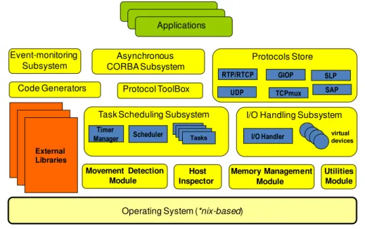
interaction with DOORS is largely asynchronous and message-based. Figure 2.1 depicts
how the various modules, subsystems and tools of the framework, together with the
ma-chine’s operating system and external libraries, can be architecturally represented.
Operating System (*nix-based) Protocol ToolBox
Movement Detection Module Memory Management Module Event-monitoring Subsystem Protocols Store
RTP/RTCP GIOP SLP TCPmux UDP SAP Asynchronous CORBA Subsystem Code Generators Utilities Module
Task Scheduling Subsystem
Scheduler Tasks Timer
Manager
I/O Handling Subsystem
I/O Handler virtualdevices
External LibrariesExternal LibrariesExternal Libraries Applications Host Inspector
Figure 2.1: DOORS architecture1
The Protocols Store contains several existing protocols already implemented, and can be
directly used by the developer to accompany new applications, such as UDP, TCPmux,
RTP and SLP.
The Protocol Toolbox contains specialized Protocol Tasks for aiding protocol
develop-ment, finite state machine implementations, Service Access Points, and
encoding/decod-ing of Protocol Data Units, bi-directional Ports used by Tasks for message passencoding/decod-ing and
multiplexers that allow M:N communications between Tasks.
The Event-monitoring Subsystem consists of tools used at runtime to monitor various parts
of a running system such as the state of tasks, internal variables, the number of messages
processed, their types, timers as well as the scheduler load. The Subsystem contains a local
event monitor capable of inspecting intra-process events in a locally running application, a
distributed event monitor capable of inspecting events simultaneously in multiple DOORS
based applications running in a network, tools for logging events into files as well as
1
a hierarchically organized symbol handling interface through which the event monitors
communicate with the application.
In addition, the Utilities and Memory Management Modules provide basic support for
implementation and runtime memory management. The Utilities Module offers basic
datatypes, structures and class templates. Frame and cell classes provide flexible ways
in storing and manipulating large octet arrays. The Memory Management Module
of-fers advanced memory management featuring basic, statistical and block memory
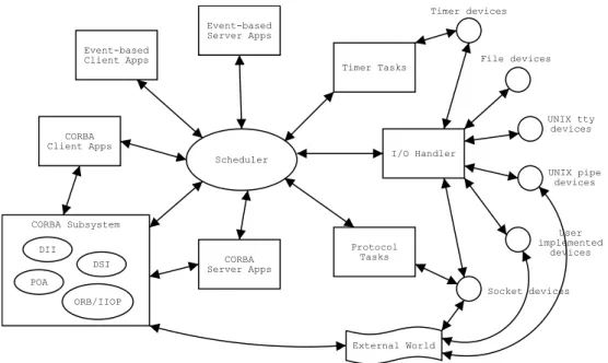
alloca-tions. Event-based Client Apps Event-based Server Apps Timer Tasks I/O Handler Protocol Tasks CORBA Client Apps CORBA Server Apps Scheduler CORBA Subsystem DII DSI POA ORB/IIOP External World Timer devices File devices UNIX tty devices UNIX pipe devices User implemented devices Socket devices
Figure 2.2: DOORS communication model2
Consequently, using this architecture it is possible to develop systems using DOORS to
communicate at multiple levels simultaneously, possessing the capacity of harnessing
inter-process communication, virtual devices, protocols and the asynchronous CORBA system
to interact with many types of external programs. Figure 2.2 illustrates the communication
model of DOORS [5]. A DOORS-process runs in a single UNIX-process with its own
scheduler and tasks that are controlled by a scheduler. A DOORS-process is a collection
of DOORS tasks and a scheduler running on one UNIX-process. A DOORS application
refers to a distributed application that may contain more than one DOORS-processes in
communication to each other. Some interesting modules of these subsystems and their
2
2.3. FRAMEWORK ARCHITECTURE 9
connections are described in detail in the following subsections.
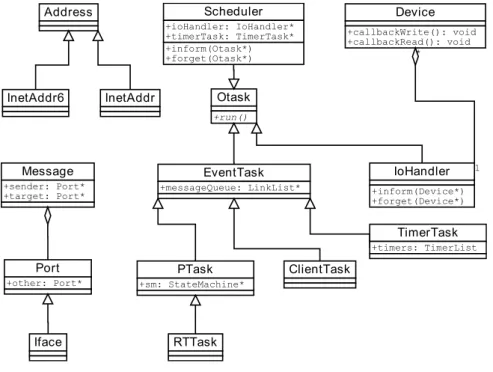
DOORS contains several libraries and applications. Figure 2.3 shows the inheritance of
some of the C++ base classes in DOORS. A task in DOORS is an object that is represented
by theOtask base class and its derivations. Otask defines an abstract method run() which
is inherited and implemented by its descendants. That function is called by a scheduler
for execution of the task’s own routines. Address is a base class for all the address type
classes in DOORS. It is just shown in the figure as an example of DOORS types. It is
specialised toInetAddr which is an address handler forInternet Protocol version 4 (IPv4)
addresses andInetAddr6 forInternet Protocol version 6 (IPv6) [6].
Otask +run() EventTask +messageQueue: LinkList* PTask +sm: StateMachine* RTTask Address InetAddr InetAddr6 Port +other: Port* Iface IoHandler +inform(Device*) +forget(Device*) ClientTask Message +sender: Port* +target: Port* Scheduler +ioHandler: IoHandler* +timerTask: TimerTask* +inform(Otask*) +forget(Otask*) TimerTask +timers: TimerList Device +callbackWrite(): void +callbackRead(): void 1 *
Figure 2.3: Examples of some of the DOORS classes3
2.3.1 Scheduler
TheScheduleris part of the Scheduling subsystem and is a task which is derived fromOtask
but it is specialised in allocating execution turns to other tasks. Various tasks might have
calls to execute at the same time. In order to execute them in DOORS, a Task needs to
ask for a execution turn to the Scheduler. In a typical DOORS application, it is called in a
loop from themain() function. The Scheduler class is an implementation of Round-Robin
3
Scheduler and it is currently the only scheduler algorithm available within DOORS. The
Scheduler maintains a list of the tasks that are being scheduled. The methods inform()
andforget() are used to add a task for scheduling and to remove it, respectively [6].
2.3.2 I/O Handler and devices
It is essential for a protocol implementation framework to provide access to the device’s
interfaces and hardware configurations, as well as to have a flexible yet efficient
input/out-put handling system. The responsibility of such service is handled by the I/O Handling
subsystem.
The I/O Handling subsystem is directly responsible for allowing event-driven tasks and
applications to communicate with external entities by introducing the concept of aVirtual
device. Such virtual devices currently include IPv4 and IPv6 network devices that perform
both unicast and multicast communication, and stream I/O facilities such as files and
pipes. Virtual devices possesses identifiers represented by file descriptors and perform
a uniform interface to tasks using functions such as open(), close(), read() and write().
However data transfer is asynchronous. Hence when writing to a device, the data is stored
in a buffer until the execution turn is obtained from theScheduler, and a callback function
is invoked to perform the actual bytewise transmission.
Therefore, the Handling Subsystem relies on a I/O Handler. The I/O Handler is derived
from Otask and it is responsible to manage the devices required for communication. It
is responsible to obtain execution turns from the Scheduler and ensure callback routines
from the devices to handle events[1].
2.3.3 Tasks, Messages and Ports
Ports provide a way to connect DOORS Tasks to each other. It has the methods
putMes-sage() andgetMessage() for putting and getting a Message object in a port for transition.
Figure 2.4 illustrates how to send a message between DOORS tasks.
2.3. FRAMEWORK ARCHITECTURE 11
specialised class contains attributes for the data being delivered through the ports. For
simplicity, this is not shown in the Figure. EventTask is derived fromTask and it supports
message queues and connecting to anotherEventTask or its descendant via a Port.
EventTask1 run()
Message Port1
EventTask2 run() Port2
message queue Scheduler
Figure 2.4: Sending and asynchronous message in DOORS4
Tasks in general communicate with each other usingPorts and passing messages through
the connectedPorts. The connection is established using connect() method provided by
Port. TheScheduler calls the run() method of aEventTask to make possible the execution
of eachTask. PTask is a descendant ofEventTask and it is specialised to tasks featuring
a finite state machine [6].
2.3.4 XML code generators
Implementing a protocol with a computer language typically follows the same pattern
of writing encoders and decoders for messages and because even the simplest protocols
feature a state machine, a programmer must also write a state machine in his protocol
implementation. Using a code generator which reads generalised representation of the
protocol messages and its state machine and creates skeleton code for the programmer to
use in his implementation speeds up the coding work.
The Code Generators are used to compile XML code parsed by the programmer. DOORS
provides three code generators:
• dpeerg: Responsible for definingProtocol Data Unit PDU’s between protocol peers;
• dsapg: Responsible for defining Service Access Point (SAP);
• dsmg: Responsible for defining finite state machines.
4
XML specifications are then parsed by generators in DOORS at compile time to produce
corresponding framework specific C++ classes such as Messages, Service Access Points,
Service Primitives as well as extended finite state machines. The example of the figure 2.5
provides a rough idea of a XML specification for the Protocol Data Units (PDUs) of the
Real-time Transport Protocol (RTP) in DOORS.
<Peer Name="RtpPeer"> <Message Name="DATA">
<Field> InetAddr srcIP </Field> <Field> InetAddr destIP </Field> <Field> Uint8 version </Field> <Field> Uint8 padding </Field> <Field> Uint8 extension </Field> <Field> Uint8 csrc_count </Field> <Field> Uint8 marker </Field>
<Field> Uint8 payload_type </Field> <Field> Uint16 sequence_number </Field> <Field> Uint32 timestamp </Field>
<Field> Uint32 ssrc </Field> <Field> Frame payload </Field> </Message>
</Peer>
Figure 2.5: PDU definiton example
2.3.5 Local Event Monitor (LEMon)
As an example on how to monitor a DOORS-process, this section describes theLocal Event
Monitor (LEMon). It was originally developed for OVOPS in Lappeenranta University of
Technology as theTextual Protocol Tracer (TPT) but was renamed to follow the naming
conventions in DOORS. Initially, it was not included in DOORS but was later adopted to
DOORS because at the time there were no monitoring tools available in DOORS. LEMon
is also useful as a protocol programming teaching and debugging tool.
LEMon provides a text-based debugging environment for tracing events and also for
send-ing user-defined events to a process. The user is not required to make changes in his
code during testing but makes it possible to try various execution scenarios using the user
Chapter 3
Network Address Translation
(NAT)
3.1
Introduction
Internet as a global and huge network has been growing exponentially. As millions of new
users and devices have been connecting every day, lack of Internet addresses has becoming
an increasingly demanding challenge. Traditionally, home and business customers connect
to the Internet with dial-up connections using an Internet Service Provider (ISP) that
dynamically assignInternet Protocol (IP) addresses that should be unique on the Internet.
Originally IP addresses were defined by IPv4 protocol. However, the number of addresses
provided by IPv4 is limited. That was one of the reasons why a complete redesign of the
protocol was started, known as IPv6. However, in order to respond to the shortage of
IPv4 addresses in the short-term, Network Address Translation (NAT) was proposed [7,
pp. 444–448], which is described in RFC 3022 [8].
The basic idea is to let a NAT-based router rewrite the address information in outgoing
and incoming messages. By changing the source private IP address and port number to
public ones for outgoing connection requests, NAT creates a mapping to allow the return
packets to reach the original initiator, and in this case, NAT is “transparent”to both
endpoints.
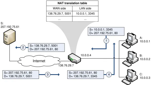
Internet
S= 10.0.0.1, 3345 D= 207.192.75.61, 80
1 S= 138.76.29.7, 5001
D= 207.192.75.61, 80
10.0.0.4 138.76.29.7
2
S= 207.192.75.61, 80
D= 138.76.29.7, 5001 3
S= 207.192.75.61, 80 D= 138.76.29.7, 3345 4
A: 10.0.0.1 B: 10.0.0.2 C: 10.0.0.3 S: 207.192.75.61
NAT translation table
WAN side LAN side 138.76.29.7, 5001
...
10.0.0.1, 3345 ...
Figure 3.1: Network address translation1
A NAT router residing at home, can be used as a gateway connection to the Internet,
having at least one network interface connected to the internal network and at least one
network interface connected to the Internet (possessing a routable IP address), in order to
connect all the machines to the Internet. Therefore, to multiple hosts in the same network,
NAT provides different private IP addresses, and a single public IP address.
Figure 3.1 is one example, and shows the operation of a NAT-enabled router. Hosts
A, B and C are in the same home network and connected to a router. The router is
a NAT-enabled router, and provides for all the computers different private IP addresses,
respectively 10.0.0.1, 10.0.0.2, 10.0.0.3, and provides a single public IP address 138.76.29.7.
Therefore, the NAT-enabled router behaves to the outside world as a single device with
single public IP address, and hides the details of the home network. This is possible due to
the fact that the NAT-enabled router maintains a NAT translation table with IP addresses
in the table entries including port numbers.
Usually the NAT-enabled routers use Dynamic Host Configuration Protocol (DHCP) to
provide addresses in the home network. Considering the example of the figure 3.1, the
host A: 10.0.0.1 wishes to reach Internet, and opens a browser to read the news in the
1
3.2. NAT TRAVERSAL 15
Server S: 207.192.75.61. The host A: 10.0.0.1 assigns the (arbitrary) source port 3345
locally and sends the packet into the LAN (transaction 1). The NAT router receives the
IP packet, checks the source port and destination, and generates a new source port 5001
for the packet, creating a new entry in the NAT translation table. Then, the NAT router
replaces the source IP address and port with its WAN-side address 138.76.29.7 and the
generated source port 5001 and sends the packet into the Internet to reach the destination
server (transaction 2). The Web server completely unaware of these changes, receives the
packet and reads the source IP address and port, sending a response back to the router
(transaction 3). The NAT router gets the response, and checks its NAT translation table
to compare the destination port number 5001 of the packet to the entries in the table.
Obtained the appropriate IP address 10.0.0.1 and destination port number 3345, the NAT
router replaces the destination port and IP address and route the packet to the host A
(transaction 4) [9].
3.2
NAT Traversal
Problems arise when a peer wants to initiate a new communication with another peer
that is connected to the Internet via NAT. Without further arrangements, the NAT-based
router will deny this communication request and will drop incoming messages. Thus, the
peer is unreachable from other peers [10]. For example, services that require
Transmis-sion Control Protocol (TCP) connections initiated from outside of the NAT (public IP
addresses), or stateless protocols such as those usingUser Datagram Protocol (UDP), can
be disrupted and the functionality of the protocol may be compromised. Developed
ser-vices following the Peer-to-peer (P2P) paradigm such as file sharing, instant messaging
and Voice over IP (VoIP) are examples of applications that suffer from the existence of
NAT.
One possible solution for this problem is to let users configure the router manually,
chang-ing the NAT tables. However, this is very inconvenient for the user and requires
admin-istration rights. Then, to allow incoming messages to reach the peer, a so-called NAT
NAT traversal techniques are typically required for clients that need to start a protocol
and the communication is affected by the NAT-based routers. Since NAT behaviour is
not standardized, many techniques of NAT traversal exist, but just one can be applied
[11]. In the next section 3.3, theSession Traversal Utilities for NAT (STUN) protocol is
described as a tool to be used in the context of NAT Traversal solutions.
3.3
Session Traversal Utilities for NAT (STUN)
As explained in section 3.2, NAT traversal techniques are required for clients that need
to start a specific protocol that is affected by the NAT-based routers. In the original
specificationSimple Traversal of User Datagram Protocol (UDP) through Network Address
Translators (NATs) (STUN) described in the RFC 3489 [12], sometimes called “classic
STUN”, was proposed as a complete NAT traversal technique. However, experience since
the publication of RFC 3489 has found that classic STUN simply does not work sufficiently
well to be a deployable solution. Therefore, a specification of an updated set of methods
published in RFC 5389 [3], Session Traversal Utilities for NAT (STUN) was proposed,
retaining the same acronym but with some differences. STUN is not a NAT traversal
solution by itself. Rather, just a tool to be used in the context of NAT traversal. This is
an important change from the previous specification (RFC 3489) that is now deprecated.
In the next sections, the STUN protocol is explained.
3.3.1 Protocol analysis
Many NAT traversal techniques require assistance from a computer server located in the
public Internet. Session Traversal Utilities for NAT (STUN) is a light-weight client-server
protocol that appeared as a tool to be used in the context of one or more NAT traversal
solutions. Interactive Connectivity Establishment (ICE) [13], Traversal Using Relay NAT
(TURN) [14], Client-Initiated Connections in the Session Initiation Protocol (SIP) [15]
and NAT Behavior Discovery Using SessionTraversal Utilities for NAT (STUN) [16] are
four defined usages of STUN at the time. Other STUN usages may be defined in the
3.3. SESSION TRAVERSAL UTILITIES FOR NAT (STUN) 17
A STUN server can be located in the public Internet in order to give useful information
to the clients behind a NAT-router and allow the private IP networks behind a NAT to
interwork with public IP networks. Therefore, the STUN server allows a client to find
out its public address/port pair that they are associated in the NAT-router. A possible
configuration is shown in the figure 3.2.
STUN Client
STUN Server NAT 1 NAT 2
Private Network 1
Private
Network 2 Internet
Figure 3.2: Possible STUN configuration
Typically hosts are connected to the internet through 1 or more NAT routers. In this
configuration two main entities (called STUN agents) exist, a STUN client and a STUN
server. The lower agent STUN client is connected to a private network 1. This network is
then connected to a private network 2 through NAT 1, and consequently private network
2 connects to the Internet through NAT 2. The upper agent resides in the public Internet
and it is the STUN server.
The STUN Client is the entity that starts the protocol. It sends STUN requests to the
STUN Server, and receives STUN responses. The STUN Server is the entity responsible
to give to the client the information that it requests. In this case, the Server receives the
STUN requests and sends the STUN responses.
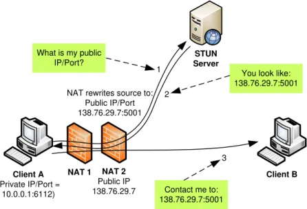
Figure 3.3 is one example of a STUN protocol communication and shows the operation
of the STUN protocol using the configuration of the figure 3.2. The client A is in a
private network 1. This network is then connected to a private network 2 through NAT
1, and consequently connected to the Internet through NAT 2. In the STUN protocol
communication, the client A is the lower agent STUN client. The client A with private
IP address 10.0.0.1 needs to find its external IP/Port in order to send this information to
NAT 1 Client A
(Private IP/Port = 10.0.0.1:6112)
NAT 2
Public IP 138.76.29.7
Client B
1
2
3 What is my public
IP/Port?
You look like: 138.76.29.7:5001
Contact me to: 138.76.29.7:5001 NAT rewrites source to:
Public IP/Port 138.76.29.7:5001
STUN Server
Figure 3.3: Use STUN to find external IP/Port
public IP/Port?”. The message passes through NAT 1 and NAT 2 and reaches the STUN
server with the source IP/Port from the NAT 2 (138.76.29.7:5001). The STUN server
reads the message, writes the reflexive IP/Port in the message (2) and sends it back to the
source IP/Port that corresponds to the NAT 2. At this point NAT 2 receives the message
2 and sends it to the NAT 1, and NAT 1 sends it to the client A. Now client A knows
its own public IP/Port used to external communications and sends a message (3) to the
client B with its own information. Now the client B knows how to contact the client A,
and it can combine this information with many NAT traversal techniques to contact the
client A.
3.3.2 Protocol operation
In detail, STUN is a client-server protocol and supports two types of transactions:
re-quest/response transactions and indication transactions. Rere-quest/response transactions
are the ones in which a client sends a request to a server, and the server returns a
re-sponse. Indication transactions are the ones in which either agent client or server sends
an indication that generates no responses.
All STUN messages must start with a fixed header that includes a method, class and a
3.3. SESSION TRAVERSAL UTILITIES FOR NAT (STUN) 19
each transaction, helping the client to associate the server responses to the requests
gener-ated. The class indicates the type of the message, which may be request, success response,
error response or indication. The method indicates which of the various requests or
indi-cations it refers to. Currently binding is the only method defined, but other methods are
expected to be defined in future documents. The RFC 5389 only defines a single method
binding, which is used either in request/response transactions or in indication
transac-tions. The binding method when used in request/response transactions can be used to
determine the particular “binding”a NAT has allocated to the STUN client. When used in
either request/responses or indication transactions, the binding method can also be used
to keep these “bindings”alive [3].
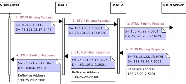
STUN Client NAT 1 NAT 2 STUN Server
S= 10.0.0.1:6112
D= 75.121.23.17:3478 S= 192.168.1.2:5001
D= 75.121.23.17:3478 S= 138.76.29.7:5001 D= 75.121.23.17:3478 S= 75.121.23.17:3478 D= 138.76.29.7:5001 S= 75.121.23.17:3478 D= 192.168.1.2:5001 S= 75.121.23.17:3478
D= 10.0.0.1:6112 Reflexive Address
138.76.29.7:5001 Reflexive Address
138.76.29.7:5001 Reflexive Address
138.76.29.7:5001
1: STUN Binding Request
6: STUN Binding Response 5: STUN Binding Response
3: STUN Binding Request
4: STUN Binding Response 2: STUN Binding Request
Figure 3.4: STUN Client-Server diagram
Typically, a STUN binding request/response is based on a scheme illustrated in the figure
3.2. The agent STUN client sends a STUN binding request message to the STUN server
and it might pass through one or more NATs between the two agents. In this example
two NATs are shown. When the STUN binding request passes through each NAT, the
NAT modifies the source transport address of the packet. As a result, the source transport
address of the packet received by the STUN server corresponds to the public IP address
and port created by the closest NAT to the server. This is called transport reflexive
address. Then, the STUN server copies the source transport address and makes it an
attribute of the body for the STUN binding response packet. This response packet passes
reflexive address in the body remains untouched. In this way, the client can learn its
reflexive transport address.
STUN usually operates on aUser Datagram Protocol (UDP). When running a STUN over
UDP it is possible that some STUN messages are dropped by the network. Reliability
of STUN request/response can be accomplished with retransmissions by the client that
should retransmit request messages. However, UDP does not provide reliable transport
guarantees. Other way is to run STUN overTransmission Control Protocol (TCP). When
reliability is mandatory TCP may be used in order to provide a connection between the
client and the server. Besides, in order to provide security,Transport Layer Security(TLS)
may be used to accompany the TCP. For this, the STUN messages may be transported
and encrypted via TCP/TLS.
3.3.3 STUN Message Structure
As explained in chapter 1, this thesis focus is a UDP implementation of the STUN
pro-tocol. Therefore, this section focuses in the specific information to reach the required
specifications.
Typically in theInternet Protocol (IP), the messages are encoded in binary using the
stan-dard network bite order (also known as big-endian, in the sense that the most significant
byte or octet is sent first). The transmission order is described in detail in Appendix B of
RFC 791 [17].
STUN messages consist of one header field followed by data (attributes) fields. Therefore,
the STUN messages must start with the same header format. A 20-byte header followed
by zero or more attributes. Then, the STUN header contains a STUN message type,
message length, magic cookie and transaction id.
Figure 3.5 illustrates the structure of the STUN header. The most significant 2 bits must
be zeroes. This is used to differentiate the STUN messages from the messages of other
protocols. The header contains the following fields:
3.3. SESSION TRAVERSAL UTILITIES FOR NAT (STUN) 21
00 STUN MESSAGE TYPE (14 bits) MESSAGE LENGTH (16 bits) MAGIC COOKIE (32 bits)
TRANSACTION ID (96 bits)
Figure 3.5: Format of STUN message header
M 11 M 10 M 9 M 8 M 7 C 1 M 6 M 5 M 4 C 0 M 3 M 2 M 1 M 0
Figure 3.6: Format of STUN Message Type field
(request, success response, error response or indication) and the message method
(this specification defines a single method, binding). Although there are four
mes-sage classes, there are only two types of transactions: request/response transactions
(which consist of a request message and a response message) and an indication
(which consists of a single indication message). Requests and indications have just
one form, although the responses are split into two forms, success messages and error
messages. The structure of the STUN Message Type is illustrated in figure 3.6. In
the message type field, the bits are order from the most significant (M11) until the
least significant (M0). The 12-bit M11 to M0 represent the encoding of the method.
The C1 and C0 represent the 2-bit encoding of the class. The class 0b00 is defined
as a request, the class 0b01 is an indication, the 0b10 is the success response, and
the 0b11 is a error response. However, this specification defines a single method,
binding, so it takes the value 0b000000000001. The bits of the method and the class
may be disposed as illustrated in figure 3.6.
• Message Length: These 16 bits must contain the size, in bytes, of the message body (not including the 20-byte header).
• Magic Cookie: These 16 bits must contain the fixed numeric value 0x2112A442.
This field was part of the transaction ID in the older specification RFC 3489. Now is
certain new attributes that were added in the new specification RFC 5389.
• Transaction ID:The transaction ID is a 92-bit randomly selected number by the initiator of the communication. It is used uniquely to identify STUN transactions.
For request/response transactions it is randomly selected by the client, and echoed
by the Server. For indications it is chosen by the agent that is sending the indication.
This field is very important. It primarily serves to correlate requests with responses,
but it also improves the security and helps to prevent certain types of attacks [3].
The details of the attributes are given in the next section.
3.3.4 STUN attributes
As explained before, the STUN messages contain a header and a data field which must
contain attributes. Each attribute must be TLV (Type-Length-Value) encoded with 16-bit
Type, 16-bit Length and a Value with variable length.
TYPE (16 bits) LENGTH (16 bits) VALUE (variable)
Figure 3.7: Format of STUN Attributes
The format of the STUN attributes is illustrated in figure 3.7. Each attribute contains
the following three fields:
• Type: The Type field specifies the type of the attribute. It must be a hex number
in the range 0x0000 - 0xFFFF. Values between 0x0000 and 0x7FFF are
compression-required attributes, which means that these attributes have to be understandable
by the agent and cannot successfully process the message unless it understands the
attribute. Values between 0x8000 and 0xFFFF are compression-optional attributes,
which means that these attributes can be ignored by the agent if it does not
under-stand them. The most common attributes, those that will be used in this project
are: 0x0009f for Error-Code, 0x000A for Unkown-Attributes and 0x0020 for
3.3. SESSION TRAVERSAL UTILITIES FOR NAT (STUN) 23
• Length: The Length field is a 16-bit numeric value and must contain the length, in bytes, of the attribute which will be posted in the Value field (not including the
32-bit Type plus Length).
• Value: The Value field must contain the attribute specified in the Type field and it
has variable length.
The next sections describe in detail the format of the most common attributes used in
this project.
XOR-Mapped-Address
The XOR-Mapped-Address attribute contains the reflexive transport address, and it is
obfuscated through the XOR function. Consequently the former (STUN server) encodes
the transport address by making a XOR operation with the Magic Cookie contained in
the header.
XXXXXXXX (8 bits) X-PORT (16 bits) X-ADDRESS (variable)
FAMILY (8 bits)
Figure 3.8: Format of XOR-Mapped-Address Attribute
The format of the XOR-Mapped-Address attribute is illustrated in figure 3.8. The most
significant 8 bits specified in the older RFC 3489 [12] were zeroes, and the address was
defined simply as Mapped-Address and was not encoded. However, deployment experience
found that some NATs rewrite the 32-bit binary payloads (IPv4 addresses), containing
the NATs public address (Mapped-Address attribute). Such behaviour was interfering the
operation of STUN [3]. Now in the new RFC [3] the address is obfuscated through the
XOR function, which means that the most significant 8 bits must be unknown value X (do
not care) and must be ignored by the receivers. This attribute also contains the following
fields:
• X-Port: The X-Port field is an 16-bit numeric value which represents the transport mapped port received in the request. This field must be computed making the XOR
operation with the most significant 16 bits of the Magic Cookie.
• X-Address: The X-Address is the transport mapped address received in the
re-quest. If the IP family is IPv4, the result should be computed by taking the mapped
IP address in host byte order and making the XOR operation with the Magic Cookie
of the header. If the IP family is IPv6, the result should be computed by taking
the mapped IP address in host byte order and making the XOR operation with the
concatenation of the MAGIC COOKIE and the TRANSACTION ID of the header.
The length depends of the family, so it has a variable length.
Error-Code
The Error-Code attribute is used to identify an error response message. It usually contains
a numeric error code between 300 and 699 plus a textual reason phrase encoded in UTF-8
defined in the RFC 3629 [18] whose semantics are consistent with SIP [19] and HTTP
[20].
RESERVED, should be 0 (21 bits) NUMBER (8 bits) REASON PHRASE (variable, maximum 763 bytes)
CLASS (3 bits)
Figure 3.9: Format of Error-Code Attribute
The format of the Error-Code attribute is illustrated in figure 3.9. The most significant
21 bits should be zeroes and are for alignment on 32-bit boundaries and receivers must
ignore these bits. The Class and the Number are encoded separately, just to make the
processing easier. Therefore, this attribute contains the following fields:
• Class: The Class field is a 3-bit numeric value which contains the hundredth digit of the error code and must be between 3 and 6.
3.3. SESSION TRAVERSAL UTILITIES FOR NAT (STUN) 25
• Reason Phrase: The Reason Phrase field is encoded in UTF-8 and is a textual
phrase which has a brief description of the error. It has variable length, depending
of the extension of the phrase.
As mentioned above, it is recommended to use phrases defined in other protocols, such
as HTTP and SIP. The most common errors are defined below and the reason phrase is
defined by the sender:
• 300: “Try Alternate ”. The client should contact an alternate server for this request.
• 400: “Bad Request”. The request was malformed.
• 401: “Unauthorized”. The request did not contain the correct credentials to proceed. The client should retry later with proper credentials.
• 420: “Unknown Attribute”. The attribute contained in the message is not under-standable by the server.
• 500: “Server Error”. The server has suffered a temporary error, and the client should
try again later.
Unknown-Attribute
The Unknown-Attributes attribute is only used in the presence of an Error-Code 420.
This attribute must contain a list of 16-bit attribute types that were not understood by
the server. The format of this list is illustrated in figure 3.10.
ATTRIBUTE 1 TYPE (16 bits) ATTRIBUTE 2 TYPE (16 bits) ATTRIBUTE 3 TYPE (16 bits) . . .
Figure 3.10: Format of Unknown-Attributes Attribute
Software
The Software attribute is an attribute with variable length. It can be sent by clients
agent that sends the STUN message. Typically the attribute has no impact in the main
operation of the protocol and is used as a tool for diagnosis and debugging purposes. It
must contain a UTF-8 encoded textual message smaller than 128 characters (which can
Chapter 4
Network Security
4.1
Introduction
In the early nineteenth century it took weeks and weeks for government agencies to send a
message to different cities. In the late nineteenth century the telegraph cut this time and
only took a few hours. At the dawn of the twenty and twenty-first century, the time has
been cut to a fraction of second with the telephone and Internet, and not just governmental
institutions but most of the citizens and companies can easily communicate with each
other. The result is that we now conduct more our communications, whether personal,
business, or civic, via electronic channels. The availability of such easy communications
has transformed not just the internationalization of the commerce, but also governmental
and personal relations in remote parts of the world.
These developments in technology have also had a profound impact in terms of privacy.
Today, most people use telephone (including cellphones) daily, and a constant use of
electronic mail, electronic commerce and much more services on the World Wide Web.
However, the reality is that the Internet and the web are extremely vulnerable and can
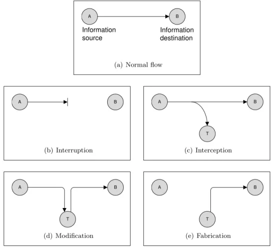
compromise communications, that by their essence can be naturally intercepted with
dif-ferent methods [21].
This chapter introduces the web security and its considerations, cryptography, and the
Transport Layer Security (TLS) protocol, providing the essential information to
stand the implementation of a secure channel between two entities. It begins with a very
brief look at Network security and electronic commerce, followed by cryptography
focus-ing on the issues that led to the creation of theSecure Socket Layer (SSL) protocol. The
next section contains a brief description of the SSL protocol and its transformation into
TLS.
4.2
Approaches to Network Security
The rapid development of the networks and the communications naturally led to business
companies, government agencies, and many individuals to easily access the World Wide
Web, and the usage of graphical Web browsers became popular. They become
responsi-ble for a big part of the traffic on the Internet, and privacy issues become more serious.
Unfortunately the reality is that the Internet and the Web are extremely vulnerable, and
communications can be easily intercepted. Business, governmental agencies and
individu-als woke up to this reality, and the demand for secure Web services grows [21].
Accordingly to Oppliger [22] in the first half of the 1990s, people started to purchase items
electronically. As an example, among the electronic payment systems, credit card
trans-actions are the most widely used. Thus, providing Web transtrans-actions security, is nowadays
a demanding challenge and extremely important. The greatest common dominator of all
these possibilities was the use of cryptographic techniques. However, for the TCP/IP
stack, there was hardly any consensus about which cryptographic techniques to use and
what layer to apply them. The remaining paragraphs of this section are based on the
chapter 3 of SSL and TLS: Theory and Practice by Rolf Oppliger [22].
After analysis and discussions, many security protocols were proposed. There are many
possibilities to invoke cryptographic techniques at various layers of the TCP/IP protocol
stack, in order to secure web transactions. Several Internet security protocols and their
placement in the TCP/IP stack are illustrated in figure 4.1 and explained below:
• Network Access Layer: On the Network Access Layer (often called Link Layer
4.2. APPROACHES TO NETWORK SECURITY 29
PGP / OpenPGP / S/MIME
S-HTTP Kerberos
SSL / TLS / DTLS
IPsec / IKE Application Layer
Transport Layer
Network Layer
Network Access Layer IEEE 802.1AE
PPTP / L2TP (IPsec/IKE)
Figure 4.1: The Internet security protocols in the TCP/IP stack1
authentication, connectionless confidentiality and integrity services to MAC frames.
Also, there are several virtual private networking (VPN) technologies and protocols,
such as the Point-to-Point Tunneling Protocol (PPTP) or the Layer 2 Tunneling
Protocol (L2TP) combined with IPsec/IKE, to provide users secure access to their
organization’s network (see next bullet). These protocols can also be used to
estab-lish secure connections in web transactions.
• Network Layer: On the Network Layer (often called Internet Layer on RFC 1122
[23]), to establish secure connections between two IP entities, there are Internet
Protocol Security (IPsec) and Internet Key Exchange (IKE) [25]. These protocols
can be used to establish secure connections in web transactions. The nice thing
about applying security at this level is that it co-resides with IP, and hence all
Internet applications are layered on top of them. Thus, it can be used to secure all
the Internet connections. However, the minus side about IPsec/IKE is that protocols
are overly complex and this makes the deployment and operation of IPsec/IKE quite
tricky.
• Transport Layer: On the Transport Layer, the goal is to enhance the current
transport protocols and invoke cryptographic techniques to provide secure
commu-nications and basic security services for web transactions. SSL/TLS is the choice to
enhance Transmission Control Protocol (TCP) on which protocols such as HTTP,
SMTP and FTP are layered. Datagram Transport Layer Security (DTLS) is the
1
choice to provide security over User Datagram Protocol (UDP) connections.
• Application Layer: On the Application Layer, the goal is to provide security
enhancing the actual application or protocol in use. In this case, it is possible either
to invoke cryptographic techniques to enhance HTTP (called S-HTTP, that is the
alternative to HTTPS), or to invoke an authentication and key distribution system
such as Kerberos to actually archieve the same level of security.
Beyond these protocols, there is also the possibility to protect web transactions in a way
that is independent from the transmission techniques. For this purpose we can have a
layer above the application layer, for example to provide secure messaging like Pretty
Good Privacy (PGP), OpenPGP orSecure MIME (S/MIME) [26].
The placement of the security protocols in the TCP/IP stack have different reasons and
consequences, and all the possibilities have advantages and disadvantages. Providing
secu-rity at a low layer has the advantage that higher layers (for example applications) become
immune and need not to be modified or to care about security in web transactions.
Pro-viding security at a high layer has the advantage that it has no impact on the networking
infrastructure, and hence the infrastructure need not to be modified.
For this approach, there is a famous principle that strongly recommends to provide security
services at a high layer. Accordingly to the end-to-end principle in system designs [27],
whenever possible, communications protocol operations should be defined to occur at
the end-points of a communications system, or as close as possible to the resource being
controlled. As an exception, the principle also states that protocol features are only
justified at lower layers of the system just if there is a performance optimization.
Following the end-to-end principle, theInternet Engineering Task Force (IETF) chartered
a Web Transaction Security (WTS) Working Group (WG) in the early 1990s 2
. The
goal of the Web Transaction Security Working Group was to develop requirements and a
specification for the provision of security services to Web transaction, e.g., transactions
using HTTP. In late 1993 Allan Schiffman and Eric Rescorla, then with Enterprise
In-tegration Technologies (EIT), came up with a proposal to enhance the HTTP protocol
2