Insights on Bubbling Formation after Drop Impact
on Thin Liquid Films
Daniela Ribeiro
1, Miguel Oliveira Panão
2, Jorge Barata
1, André Silva
1,* 1AEROG – LAETA, University of Beira Interior, Covilhã, Portugal
2
ADAI – LAETA, University of Coimbra, Coimbra, Portugal
*Corresponding author:[email protected]Abstract
Over the years, the phenomena obtained when a drop impinges upon a dry, wetted or heated surface have been thoroughly studied. In previous works, the existence of splash was investigated by the authors with the goal of evaluating the possible implementation of biofuels in the civil aviation and it was found an episode of a phenomenon, seldom reported in the literature under specific pre-impingement conditions. The mechanism that leads to a bubble formation has two stages. After the drop impacts a steady liquid film, prompt splash occurs followed by crown splash. In the first stages of crown splash, the uprising sheet propagates almost normal to the liquid film, but its radius at the base continues to expand, eventually leading to the inward collapse of the crown bounding rim. Thus, the top of the crown closes in a bubble-like shape with the formation of two jets, one upwards and other downwards. The upward jet eventually disappears due to gravitational influence, while the downward jet continues to grow until it reaches the liquid film, attaching to it, stretching and detaching from the top at the hemispheric thin-sheet, forming a perfect bubble. Many secondary droplets fall on the bubble and one of them will eventually break the dome, leading to more secondary atomization.
The few works reported in the literature referring to this phenomenon as “bubbling” or “floating bubble,” scarcely explore the hydrodynamic mechanism associated with this bubble formation and occurrence, mainly focusing on droplets impacting upon deep pools. However, in a previous study, the authors observed this event for a liquid film dimensionless thickness of 0.5 in a fluid mixture of Jet A-1 and biofuel NEXBTL.
In this study, the impact conditions in the experiments performed allow to recreate the floating bubble with 100% of occurrence. After that, the authors present an extensive characterization of the bubbling phenomenon to under-stand better the mechanisms which lead to its formation, as well as its practical significance. A high-speed digital camera acquires several images of the floating bubble formation from different points of view (side and bottom). Namely, capturing the phenomenon from below, high-quality images allow retrieving essential data to describe the hydrodynamic mechanism accurately. The most relevant features include the bubble height and diameter, and the propagation velocity of the first perturbation imposed on the liquid film.
Keywords
Droplet impingement, Bubbling, Floating Bubble and Liquid film. Introduction
A single droplet impinging upon a liquid film is the fundamental event in multiple applications such as fuel injection in internal combustion engines, corrosion of turbine blades, meteorite impact upon space vehicles, surface cooling, spray painting, coatings, and also in natural phenomena like soil erosion by rain drops. In previous works, Ribeiro et al. [1] investigated the outcome of these impacts with the goal of implementing biofuels in internal combustion engines. Six different phenomena were spotted and one of them involving bubble entrapment is rarely investigated in the literature. Therefore, the purpose of the work presented here is to improve the knowledge of bubble entrapment on the single drop impact onto thin and shallow liquid films. The physical description of this outcome, nominated as bubbling or floating bubble, corresponds to the closing of an uprising crown sheet, eventually forming a bubble. Worthington [2] dedicated a section of his book to the building of bubbles for high falls. He increased the impact height in favor of evaluating its influence upon the crater depth, and a new phenomenon appeared. He described it by the closure of the crater “mouth” to form a bubble and suggested that both the upward liquid flow towards the crown rim and the action of surface tension promoted the formation of the bubble structure. He also reported that if the impact velocity is not sufficiently high the crown almost closes or it closes but quickly reopens.
A few decades later, Engel [3] studied the impact of single droplets upon liquid targets to simulate micrometeorites shocking on spatial vehicles. The author focused on the cavities originated by these impacts. Again, he reported that if the impact energy exceeds a certain threshold, the upper edge of the bubble-thin cylindrical sheet rising at the top of the cylindrical wave will, at last, neck in and close to form a spherical bubble above the cavity. Then, a liquid jet develops at the closure point moving downwards via the cavity floor. At the same time, an upward moving jet meets and mix with the downward moving jet.
Later, Pan et al. [4] focused their work on the impact of high-speed droplets upon liquid layers and reported that at large Weber numbers (W e ≥ 2570) and large dimensionless film thicknesses (δ < 9), the ejected crown closes and forms a bubble. They found this regime interesting for further investigation, noticing that more droplets are emitted from the central jet relative to the case without the bubble. Additionally, the transition boundary decreases monotonically with the increase of the dimensionless film thickness.
Motzkus et al. [5] studied mechanisms which could lead to the formation of microdroplets concerning the emission of airborne particles with respect to the safety of nuclear facilities. Prompt splash, finger pinching, and bubble bursting are examples of those mechanisms. They reported that for low surface tension fluids, the bubble bursting provided a high production of droplets with sizes smaller than 15µm. The bubble progressively becomes thinner under the effect of the rising bubble and the drainage of the liquid. When the hemispherical thin-sheet reaches a critical thickness, the liquid sheet breaks and produces tiny droplets. Several parameters influence the number and size of the emitted droplets: bubble size, air-liquid surface tension, liquid viscosity and thickness of the bubble sheet. However, they only spotted one case with formation and break up of bubbles.
A couple of years later, Pan and Hung [6] extended their research and mentioned that the enclosure of the crown was due to the bending of the upwardly ejected sheet by the gravity force. The bubble trapped inside could cause some underwater perturbations that will eventually affect the transport of fluid or transmission of sound waves. The two jets upwards and downwards were also identified by them.
More recently, Geppert et al. [7] experimental and numerically investigated the impact morphology of droplet im-pingement upon liquid films for two-component systems, in pursuance of simulating the diesel droplets impinging upon the lubricating oil film that covers the combustion chamber walls. However, they detected two additional phenomena, jet and bubble formation, and their occurrence was not occasional. Both the central jet and bubble formation have been already spotted for one-component interactions, but mainly for thicker liquid films (δ ≥ 0.5). Thus, it is possible to assume that even for one-component systems, the dynamic of splashing is far more complex than the typical deposition/splashing boundary. In their experiments, the bubble formation happened for δ ≥ 0.2 and We> 1100, and they agreed with Worthington [2] about the effects which originate bubbling. To conclude, they recognise, at first side, that the lifetime of splashing is longer when the crown sheet closes to form a bubble. In the same year, Liang and Mudawar [8] recognize that a few authors [5, 9, 10] reported the existence of narrow or closed rims and they believed that this large bubble depends strongly on the dimensionless film thickness and impact velocity.
Considering all these facts and conclusions presented in the literature, the impact conditions where bubbling was previously found were recreated, including the fluid used, which is a mixture of 75% Jet A-1 and 25% NEXBTL. Being Jet A-1 a conventional Jet Fuel (JF) and NEXBTL (Neste Renewable Diesel) an HVO (Hydro-processed Vegetable Oil), a biofuel. The main goal of this study is to reproduce the bubbling phenomenon, understand its occurrence, formation mechanisms, main features, and physical significance. For that, the experimental setup was adapted, the phenomenon was captured through high-speed imaging and the data analysed.
Experimental Method and Setup
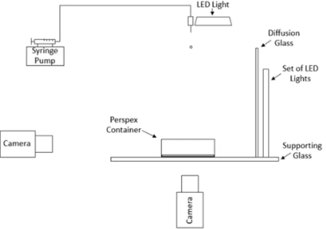
To perform these tests, the experimental setup has two different configurations since images were taken both from the side and from below. The camera and illumination changed places to provide the different perspectives of the phenomenon. Besides that, the experimental facility, shown in Figure 1, is essentially composed of four main sections: image acquisition system, drop generator, impact surface and impact site illumination.
Figure 1. Scheme of the experimental facility.
The images were acquired by a high-speed digital camera Photron FASTCAM mini UX50 with 1.3 Megapixel resolu-tion at frame rates up to 2, 000f ps (frames per second) and up to 160, 000f ps at reduced image resoluresolu-tion. A Macro Lens Tokina AT-X M100 AF PRO D with a minimal focus length of 0.3m was also used. For all the data, the image resolution was 1280x1024, the exposure time was 1/5120s and the frame rate was 2, 000f ps. The droplet dispens-ing system is composed of a syrdispens-inge pump NE-1000 connected to a straight tip stainless steel needle. The syrdispens-inge pump operates at a pumping rate of 0.5ml/min allowing the droplet to leave the needle when gravity exceeds the surface tension forces. The impact surface was a perspex container and its dimensions were calculated in order to assure that the walls of the container do not interfere with the outcome. This container holds the liquid film. The illumination of the impact site is vital to improve the quality of the data. The room was kept dark and the only light source was a set of LED lights parallel to the droplet falling plan for the side images and a LED light parallel to the
impact surface for the bottom images. In addition, a diffusion glass was placed between the source of lighting and the camera for the side images, since the same was not possible for the images taken from below, at least for the current experimental apparatus.
As previously stated, the fluid used was a mixture of 75% Jet A-1 and 25% NEXBTL. Its physical properties were measured: ρ = 795 kg/m3, σ = 25.5mN/m and µ = 1.4 × 10⁻³P a·s. The needle used has an inner diameter of 1.5mmwhich produces 3.0mm droplets. The impact velocity was kept constant at U0 = 4.2m/sfor all the
exper-iments, providing a set of constant dimensionless numbers presented in Table 1, including the Weber, Ohnesorge (Oh), Laplace (La), Bond (Bo), Froude (F r) and Capillary (Ca) numbers. It is important to mention that these dimensionless numbers were calculated considering the physical properties of the liquid. Since this is a prelimi-nary study, all these dimensionless numbers were calculated in pursuance of finding their role in the phenomenon formation.
Table 1. Dimensionless numbers
We Oh·103 La Re Bo Fr Ca
1667 5.824 29486 7010 2.76 600 0.23
The image data processing is essential to allow the measurement of the phenomena main features. In this case, the bubble height and diameter, and the propagation velocity were measured using the acquired images. Thus, an algorithm for image treatment was created in the software MATLAB. To measure these features, an image of the background is subtracted to the original image. Then, through image binarization, the image is transformed into zeros and ones, i. e., black and white pixels. It is possible to measure the different structures by counting pixels. Thus, the pretended sizes were obtained multiplying by the pixel size. The height and diameter values were obtained with an accuracy of ±0.03mm and the impact velocity with ±0.006m/s.
Results and discussion
This section begins with the explanation of the bubbling formation event using the results obtained from high-speed visualization. The images show two perspectives. The most common is a side view and the novelty resides in the observations made from below.
After explaining the phenomenon under study, the analysis focus on two features of the bubble formed after drop impact on the liquid film. Some considerations begin with the effect of different dimensionless film thicknesses on the bubble geometry and also on the velocity propagation of the first film perturbation.
Phenomenon Description and Visualization
In this study, the experiments and analysis focus on the bubbling formation. Therefore, to ensure reproducibility of the phenomenon, several impact velocities were tested for the dimensionless film thickness (δ) of 0.5, with the fluid and droplet diameter mentioned above. The impact velocity for which this phenomenon occurred with 100% repeatability was U0 = 4.2m/s. The image sequence of bubbling presented in Figure 2 describes the main
hydro-dynamic structures of the investigated phenomenon.
After impact on the steady liquid film, the droplet prompt splashes (τ = 0), followed by the formation of an uprising crown splash (τ = 14). In the first stages of crown splash, the uprising sheet propagates almost normal to the liquid film, but the radius of the crown-base continues to expand (τ = 14), eventually leading to the inward collapse of the crown bounding upper-rim. Several secondary droplets were ejected by the fingering breakup at the top of the crown. The crown rim is continuously fed with liquid, increasing its diameter which, eventually, leads to the crown wall inward collapse at τ = 42. The closing of the crown at the top begins forming a bubble-like shape (τ = 56), and two jets (τ = 70). One jet moves upwards and the other in the downward direction. While the upward jet eventually stops and recedes due to gravitational forces, the downward jet reaches the horizontal liquid film (τ = 98), attaches to it, stretches and detaches from the top at the hemispheric thin-sheet (τ = 126 and τ = 140). After this detachment, at τ = 210, a perfect bubble fully formed remains on the liquid film.
Meanwhile, many secondary droplets strike the bubble and one of them will eventually break the dome forming even more secondary droplets (τ = 291.2). These secondary droplets will impinge immediately on the liquid film inducing more perturbations. As the time evolves, the perturbations cease and the liquid film return into the initial steady condition.
As stated by Motzkus et al. [5], the liquid in the bubble’s hemispherical thin-sheet, progressively drains by the walls becoming thinner and more susceptible to break due to the impact of secondary droplets created by the crown splash. The wavy pattern observed at τ = 210 in Fig. 2 evidences the draining of liquid from the bubble thin-wall to the liquid film.
It is important to mention that the crown liquid sheet angle, in the first stages of splashing, is almost normal to the liquid film (τ = 14). According to Wang and Chen [11], the uprising crown wall is almost perpendicular to the horizontal liquid film for the dimensionless film thickness of 0.5. Additionally, Fedorchenko and Wang [12] reported that the crown angle depends entirely on the liquid film thickness, regardless the impact velocity and liquid physical properties.
It seemed important to observe the phenomenon from below since the authors cannot find any publication which shows this perspective of the floating bubble. In this sense, the high-speed digital camera, mounted below the glass
τ = 0 τ = 14 τ = 42 τ = 56 τ = 70 τ = 98 τ = 126 τ = 140 τ = 210 τ = 252 τ = 291.2 τ = 294
Figure 2. A sequence of images showing the bubbling phenomena for the following impact conditions: 75%JF/25% HVO,
D0=3.0mm, U0=4.2m/s, δ=0.5.
supporting the Perspex container, allows obtaining a sequence of images depicted in Figure 3.
In Figure 3, the droplet impinges upon the liquid film (τ = 0), and shortly after, the crown sheet rises and starts bending inwards (τ = 14), as can be seen by the top of the crown sheet identified at this frame by the red arrow. This frame corresponds to τ = 14 in Figure 2. The crown sheet closes at τ = 28 by the union of several jets at the top of the crown sheet, indicated by the red arrow in this frame. This crown closure matches with frame τ = 56 in Figure 2. At τ = 70, in the center (delimitated by a red circle), it is possible to see the downward jet connecting to the bottom of the crater, frame τ = 98 of Figure 2 shows that from the side. Nothing could be concluded about the upward jet, since it cannot be seen in this visualization method. The downward jet continues its motion to the cavity floor (τ = 140). At this frame, it is easily perceived the bubble thin liquid sheet by the large white circle, and the jet by the dark circle in the middle. Later, at τ = 420, the downward jet detaches from the thin-liquid dome, forming a perfect empty bubble, the thin white circumference within the dark circle, pointed by the red arrow. To help visualization see frame τ = 210 in Figure 2. At this time, the liquid film is almost steady, and the dark portion of the circle identify the connection between the bubble and the liquid film. In this case, at τ = 441 the bubble breaks by reaching the critical thickness of the hemispherical liquid sheet or by the impingement of a tiny secondary droplet (frame τ = 252 in Figure 2). It is impossible to assure that from this point of view. The following frames show the perturbations imposed on the liquid film by the bubble bursting. The evolution of the pattern created at the liquid film by the breakup of the bubble is showed in frames τ = 448, τ = 455, τ = 469, and τ = 490.
By virtue of these images from below, it was possible to undoubtedly measure the bubble diameter and also the propagation velocity of the first perturbation imposed on the liquid film by the droplet impact, addressed ahead. Comparing both sequences of images is easy to infer that the phenomenon lifetimes were different. The lifetime of the phenomena in the several experiments performed was accounted to understand their similarities. However, the lifetime of bubbling strongly depends on the amount of secondary atomization which falls on the bubble when the thickness is thin enough to allow the bubble bursting.
Thereafter, the influence of the dimensionless film thickness in the bubbling formation was investigated. To achieve this, experiments were performed for dimensionless film thicknesses between 0.1 and 1, with gaps of 0.1. For the thinner liquid film, only prompt and crown splash was spotted, the phenomenon was too quick to allow the crown
Figure 3. Sequence of images showing the bubbling phenomena from below for the following impact conditions: 75%JF/25%
HVO, D0=3.0mm, U0=4.2m/s, δ=0.5.
closure. For δ = 0.2 and δ = 0.3, some episodes of bubbling were observed but in less than 50% of the cases. From δ = 0.4to δ = 1, there was 100% of bubbling formation and the crown sheet angle seems almost perpendicular to the horizontal liquid film for all the cases. With that in mind, it was concluded that the crown sheet angle does not depend only on the dimensionless film thickness as Fedorchenko and Wang [12] suggested. Nevertheless, this fact will be explored in future works. Following Pan et al. [4] conclusions, the factor for the crown to close relies on the balance between the upward motion of the sheet and the downward pull of gravity. Therefore, it could be expected that the enclosure of the crown reduces with lowering the dimensionless film thickness since the ejection inertia becomes weaker. This fact was validated since for δ = 0.1 bubbling never occurred and only some events were spotted for δ = 0.2 and δ = 0.3. Moreover, increasing the dimensionless film thickness seems to thicken the hemispherical liquid-sheet and it takes a longer time to burst. Geppert et al. [7] also detected this.
Regarding a possible boundary for the bubbling occurrence much more experiments are necessary including more fluids, impact velocities, and droplet diameters. Nevertheless, for this fluid, bubbling is formed for a minimum Weber number of W e = 1667 for δ ≥ 0.2, but only with 100% occurrence for δ ≥ 0.4. Reminding that Pan et al. [4] spotted it for W e ≥ 2570 and δ ≈ 1 and Geppert et al. [7] for W e > 1100 and δ ≥ 0.2. Considering all the studies reviewed, none of them named other dimensionless number, so the only comparative element is the minimum Weber number for the bubbling occurrence combined with the dimensionless film thicknesses used. The search for a boundary which predict the bubbling formation seems justifiable.
The cavity formed underneath the bubble and the physical parameters which govern bubbling are worthy of attention. If the liquid film is thin, the impact crater quickly collides with the solid surface at the bottom. The impact crater was photographed, and that assumption seems to be completely accurate. After the droplet impinges the liquid film, the cavity almost immediately touches the bottom of the container. That could influence other factors of the phenomenon like capillary instability. Roisman et al. [13] mentioned that capillary waves arrive on the surface of the cavity and the same seems to happen in this case.
Bubble Geometry
Understand the resultant structures of this phenomenon is crucial to support its future applications. Thus, the two most evident features were measured, the bubble height and diameter. As mentioned before, the acquired data
were analysed through algorithms created with the MATLAB software. To measure the bubble height, the images taken from the side were used and for the bubble diameter the images from below. Investigate the influence of the dimensionless film thickness upon these two features is our main goal since both the initial droplet diameter and impact velocity were kept constant during all the experiments. In that way, the mean bubble height obtained for ten tests for each dimensionless thickness between 0.4 ≤ δ ≤ 1 were measured and normalized by the droplet diameter. The bubble height (hB) and dimensionless bubble height (h
∗
B) depending on the dimensionless film thickness are
presented in Table 2. It was found that the bubble height seems to be independent on the dimensionless film thickness for 0.4 ≤ δ ≤ 1. The values obtained for the different thicknesses are quite similar and about 2.4 times the droplet initial diameter (hB≈ 2.4D0).
It was decided to use the images taken from below to measure the bubble diameter since it is well defined, as can be seen in Figure 3 (τ = 420). Table 2 shows bubble diameter (DB) and dimensionless bubble diameter (DB∗) for the
different dimensionless film thicknesses. Again, the bubble diameter seems independent of the dimensionless film thickness. The values obtained are again quite similar and almost six times the droplet initial diameter (Db≈ 5.8D0).
It is believed that the droplet initial diameter could play a major role in the bubble size. In this way, different diameters will be tested in future works.
Table 2. Bubble height, dimensionless bubble height, bubble diameter and dimensionless bubble diameter for the different
dimensionless film thickness. The uncertainty values are absolute and obtained with a confidence interval of 95%
δ hB[mm] h∗B DB[mm] D∗B 0.4 7.2 ± 0.009 2.4 17.0 ± 0.008 5.7 0.5 7.1 ± 0.024 2.4 18.5 ± 0.016 6.1 0.6 7.2 ± 0.010 2.4 19.0 ± 0.018 6.3 0.7 6.9 ± 0.005 2.3 16.9 ± 0.021 5.6 0.8 7.2 ± 0.007 2.4 16.7 ± 0.010 5.5 0.9 6.9 ± 0.006 2.3 17.0 ± 0.016 5.6 1.0 7.2 ± 0.002 2.4 17.7 ± 0.018 5.9
Propagation Velocity of the First Film Perturbation
The images from below enhanced the knowledge about the phenomenon and the droplet-film impact itself. The propagation velocity (Up) of the first perturbation induced on the liquid film was investigated in order to create a
correlation which could be used in numerical modeling and help recreate this phenomenon. In Vasconcelos et al. [14] the impact conditions where bubbling was spotted in the previous work [1] were numerically tested but although the crown sheet collapsed inwards it never closed. It is important to mention that those simulations were 2D and 3D simulations of the same set of impact conditions are required. To measure the propagation velocity, the first 11.5ms after impact were considered for each dimensionless film thickness between 0.4 and 1. In Figure 4 is possible to understand the evolution of the first perturbation with time.
τ = 0 τ = 7 τ = 14
Figure 4. Sequence of images illustrating the propagation velocity of the first perturbation on the liquid film.
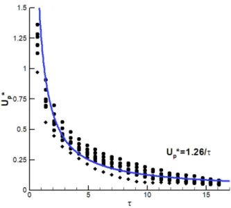
The propagation velocity was normalized by the droplet impact velocity, Up∗ = Up/U0, and Figure 5 shows its
evolution in the dimensionless time (τ ).
As can be seen, by the graphic, the dimensionless propagation velocity decreases with time following a defined trend. The blue line in the graphic represents an empirical correlation for the time evolution of the dimensionless propagation velocity of the first perturbation on the liquid film valid for 0 < τ ≤ 16.1. The dimensionless propagation velocity is inversely proportional to the dimensionless time and proportional to a parameter a which depends on the impact conditions, eq. (1).
Up∗=
a
τ (1)
If the variation of the dimensionless film thickness was not considered, the empirical constant a = 1.26 with a correlation coefficient of R2= 0.91.
Figure 5. Dimensionless propagation velocity of the first perturbation on the liquid film versus the dimensionless time.
Therefore, analysing the behaviour of the curves for each dimensionless film thickness separately shows that the parameter a is truly influenced by the dimensionless thickness. Although, its influence is not well defined for the available data. In this way, in eq. (2) values are proposed for the parameter a depending on the dimensionless film thickness tested in the experiments.
a = 0.90, δ = 0.4 a = 1.15, 0.5 ≤ δ ≤ 0.6 a = 1.30, 0.7 ≤ δ ≤ 1 (2)
As already mentioned, these a values are properly for the present work. However, for similar impact conditions, they could provide a good accuracy. Further investigation will be made changing other impact conditions (droplet diameter, fluids, impact velocity) in pursuance to assess their influence upon the parameter a.
Conclusions
The focus of this study was the bubbling phenomenon where a bubble is formed by the closure of the crown sheet. The phenomenon was reproduced for a constant W e of 1667 for 0.4 ≤ δ ≤ 1 with 100% occurrence. For the thinner film tested, δ = 0.1, it never occurred, and some events were seen for δ = 0.2 and δ = 0.3. Thus, lowering the depth of liquid film reduces the enclosure of the crown. Bubbling was captured both from the side and from below and it was physically described. Several factors could promote its formation. For all the dimensionless film thicknesses tested, the crown sheet angle was almost normal to the horizontal liquid film in the first stages of splashing which promotes its enclosure inwards. Increasing the liquid film thickness seems to thicken the hemispherical liquid-sheet and consequently, its lifetime. The liquid in the hemispherical sheet progressively drains by the walls turning the bubble thinner and susceptible to break. The phenomenon lifetime strongly depends on the amount of secondary atomisation which falls on the bubble when its thickness is thin enough to allow the bubble bursting.
The search for a boundary which predicts the bubbling formation seems justifiable. However, more experiments are necessary, including more fluids, impact velocities, and droplet diameters. The cavity formed collides with the solid surface at the bottom. That could influence other factor of the phenomenon like the capillary instability. Understand the resultant structures of this phenomenon is crucial to support its future applications. Both the dimensionless bubble height and diameter seem to be independent on the dimensionless film thickness. It is believed that the droplet initial diameter could play a major role in the bubble size. In this way, different diameters will be tested in future works. It was proposed an empirical correlation for the dimensionless propagation velocity of the first perturbation imposed to the liquid film in function of the dimensionless time.
Acknowledgements
The present work was performed under the scope of Aeronautics and Astronautics Research Center (AeroG) of the Laboratório Associado em Energia, Transportes e Aeronáutica (LAETA) – activities and it was supported by Fundação para a Ciência e Tecnologia (FCT) through the project UID/EMS/50022/2019 and also by the Ph.D. scholarship with the reference SFRH/BD/140009/2018.
Nomenclature a Parameter
Bo Bond number (Bo = W e/F r) Ca Capillary number (Ca = W e/Re) D0 Droplet diameter [mm]
DB Bubble diameter [mm]
D∗B Dimensionless bubble diameter (D ∗
B= DB/D0)
F r Froude number (F r = W e/Bo) h Film thickness [mm]
hB Bubble height [mm]
h∗B Dimensionless bubble height (h ∗
B= bB/D0)
La Laplace number (La = ρσD0/µ2)
Oh Ohnesorge number (Oh =√W e/Re) Re Reynolds number (Re = ρD0U0/µ)
t Time after impact [ms] U0 Droplet impact velocity [m/s]
Up Propagation velocity [m/s]
Up∗ Dimensionless propagation velocity (U ∗
p = Up/U0)
W e Weber number (W e = ρU02D0/σ)
δ Dimensionless film thickness (δ = h/D0)
µ Viscosity [Pa·s] ρ Density [kg/m3] σ Surface Tension [N/m] τ Dimensionless time References
[1] Ribeiro, D., Cunha, N., Barata, J., Silva, A., July 22-26, 2018, 14th International Conference on Liquid Atomiza-tion & Spray Systems.
[2] Worthington, A. M., 1908, “A study of splashes.”
[3] Engel, O. G., 1966, Journal of Applied Physics, 37(4), pp. 1798–1808.
[4] Pan, K. L., Cheng, K. R., Chou, P. C., Wang, C. H., 2008, Experiments in Fluids, 45(3), pp. 435–446. [5] Motzkus, C., Gensdarmes, F., Géhin, E., 2009, Journal of Aerosol Science, 40(8), pp. 680–692. [6] Pan, K. L., and Hung, C. Y., 2010, Journal of Colloid and Interface Science, 352(1), pp. 186–193.
[7] Geppert, A., Chatzianagnostou, D., Meister, C., Gomaa, H., Lamanna, G., Weigand, B., 2016, Atomization and Sprays, 26(10), pp. 983–1007.
[8] Liang, G., and Mudawar, I., 2016, International Journal of Heat and Mass Transfer, 101, pp. 577–599. [9] Ninomiya, N., and Iwamoto, K., 2012, AIP Conference Proceedings, 1428(2012), pp. 11–17.
[10] Guo, J.-H., Dai, S.-Q., Dai, Q., 2010, Acta Physica Sinica, 59(4), pp. 2601–2609. [11] Wang, A. B., and Chen, C. C., 2000, Physics of Fluids, 451, pp. 2155-2158. [12] Fedorchenko, A. I., and Wang A., 2004, Physics of Fluids, 16(5), pp. 1349-1365. [13] Roisman, I. V., Van Hinsberg, N. P., Tropea, C., 2008, Physical Review E, 77(4), pp. 1–7.
[14] Vasconcelos, D., Ribeiro, D., Barata, J., Silva, A., April 14-17, 2019, 4th Thermal and Fluid Engineering Con-ference.