U
NIVERSIDADE DE
L
ISBOA
Faculdade de Ciˆencias
Departamento de Inform´atica
LOAD BALANCING IN REAL SOFTWARE DEFINED
NETWORKS
Gonc¸alo Miguel Alves Semedo
DISSERTAC
¸ ˜
AO
MESTRADO EM ENGENHARIA INFORM ´
ATICA
U
NIVERSIDADE DE
L
ISBOA
Faculdade de Ciˆencias
Departamento de Inform´atica
LOAD BALANCING IN REAL SOFTWARE DEFINED
NETWORKS
Gonc¸alo Miguel Alves Semedo
DISSERTAC
¸ ˜
AO
MESTRADO EM ENGENHARIA INFORM ´
ATICA
Especializac¸˜ao em Arquitectura, Sistemas e Redes de Computadores
Dissertac¸˜ao orientada pelo Prof. Doutor Fernando Manuel Valente Ramos e co-orientado pelo Prof. Doutor Nuno Fuentecilla Maia Ferreira Neves
Acknowledgments
First of all I want to thank my parents for all the support and encouragement that was fundamental for me to achieve my goals. Without them I would not got this far, not only because of all the investment they made in my education, but also because of all the love and firm hand that kept me in the right path. I like to thank my sister for putting up with me and help me in my journey, she was also very important for me to achieve my goals. I also want to thank the rest of my family, especially my cousins Ricardo Alves, Andr´e Torrinha and Pedro Paiva throughout the time we spend together to relieve stress by doing some exercise or just by hanging out.
I want to give a special thanks to my longtime friends Diogo Santos, Miguel Silva and Susana Vilhena for all their friendship, support and advice.
I want to give a great thanks to all my companions Carlos Barata, Jo˜ao Martins, F´abio Santos, Tiago Aparicio, Tiago Posse, Jo˜ao Nascimento, Rafael Oliveira, Jos´e Carilho and Rita Henriques for all these 6 amazing years that we spent together on this journey that was the college life. We had awesome moments and lots of night outs, some of them partying while others studying.
Of course, I must thank my advisors professor Fernando Ramos and professor Nuno Neves for the opportunity to join this project and for all their guidance.
Finally I want to thank Vin´ıcius Congo for helping me with the bioinformatics appli-cation that made possible the third test and a more accurate result.
Resumo
Actualmente, configurar uma rede pode ser um processo demorado e penoso, prin-cipalmente quando estamos a falar de redes constitu´ıdas por centenas de routers e swit-ches. ´E necess´ario configurar cada um destes equipamentos individualmente, normal-mente usando a linha de comandos, num processo muito suscept´ıvel a erros. As redes definidas por Software ou Software Defined Networking (SDN) [19, 27] s˜ao um novo pa-radigma que surgiu recentemente e que visa resolver estes problemas de configurac¸˜ao e de gest˜ao de redes. A ideia principal de uma SDN consiste na centralizac¸˜ao da l´ogica do controlo da rede num controlador SDN (ou num grupo de controladores), que con-trola e monitoriza todo o comportamento da rede. Assim, h´a uma separac¸˜ao entre o plano de controlo que tem por func¸˜ao preencher as tabelas de encaminhamento dos switches com base nas decis˜oes do operador da rede (ou das aplicac¸˜oes que tomam as decis˜oes), e o plano de dados, isto ´e, o encaminhamento dos pacotes. Esta separac¸˜ao ´e poss´ıvel atrav´es da definic¸˜ao de uma API entre os switches e o controlador, como por exemplo o OpenFlow [30]. Uma rede SDN possibilita que as redes sejam program´aveis permitindo a definic¸˜ao do comportamento da rede a partir do controlador, facilitando a definic¸˜ao e implementac¸˜ao de aplicac¸˜oes complexas tais como balanceamento de carga, encaminha-mento ou seguranc¸a.
O objectivo deste trabalho consiste na construc¸˜ao de um balanceador de carga usando este novo paradigma. As principais diferenc¸as em relac¸˜ao aos distribuidores de carga convencionais, que s˜ao baseados em hardware especializado e caro, ´e que o que propomos ´e baseado em software sendo uma aplicac¸˜ao que corre em cima de um controlador. Al´em disso faz balanceamento de carga considerando n˜ao s´o o servidor para onde devemos enviar os dados, mas tamb´em o melhor caminho para chegar at´e ao servidor escolhido.
Para a construc¸˜ao do nosso projecto us´amos o controlador Floodligth [8], feito em Java. Usando este controlador avali´amos v´arias combinac¸˜oes de algoritmos de escolha de servidor e de algoritmos de escolha de caminho.
Como acreditamos n˜ao existir um algoritmo que seja o mais indicado para todas as aplicac¸˜oes, desenvolvemos uma nova aplicac¸˜ao de balanceamento de carga para redes SDN: MALOB (Multi-Algorithm Load Balancer), uma aplicac¸˜ao que selecciona o algo-ritmo de acordo com o tipo de pedido.
Um dos pontos mais relevantes deste trabalho prende-se com a sua avaliac¸˜ao. Para a realizac¸˜ao dos v´arios testes recorremos `a GENI [13], uma rede experimental de larga escala. A GENI possibilita o desenvolvimento de uma grande variedade de experiˆencias, tais como, desenho e avaliac¸˜ao de novos protocolos, servic¸os distribu´ıdos, gest˜ao de conte´udos ou servic¸os de gest˜ao de redes, usando uma rede f´ısica real. Uma das principais raz˜oes pela qual opt´amos pela GENI foi o facto de esta nos permitir explorar o potencial de novas tecnologias como as SDN. Com uma avaliac¸˜ao experimental feita numa rede real como a GENI conseguimos resultados que nos permitem tirar conclus˜oes mais precisas relativamente ao impacto do nosso trabalho.
Palavras-chave: Software-Defined Networking, Balanceamento de carga, OpenFlow, GENI, Floodlight.
Abstract
Nowadays, network management can be a painful and tedious process, especially when we consider large networks with hundreds of switches and routers. In traditional networks, it is necessary to configure each equipment, one by one, typically using a com-mand line in an error-prone process. Software Defined Networking (SDN) [19, 27] is a new paradigm that aims to change this current undesirable state of affairs. The main idea of SDN consists in logically centralizing network control in a SDN controller (or a cluster of controllers), which controls and monitors the behavior of the network. The goal is to separate the control plane from the data plane. This separation is possible by means of an API between the switches and the controller such as OpenFlow [30]. Networks thus become programmable, allowing the definition of the behavior of the entire network from a vantage point, the controller, thus facilitating the creation of advanced network policies, such as load balancing, routing and security.
The main goal of this project is to develop and evaluate a load balancer using this new paradigm. Conventional load balancers are expensive specialized hardware equipment whereas our proposal is based on a software application running on top of the SDN con-troller. Additionally, our solution enables load balancing to be performed not only based on server choice, but also on the best path to the chosen server.
To achieve our goal we used the Floodlight controller [8] implemented in Java. Us-ing this controller we evaluated several combinations of algorithms for server and path selection.
As particular algorithms are suitable for particular applications, we propose a Multi-Algorithm Load Balancer (MALOB), a load balancing application for SDNs that has the capability to adapt to the different types of requests, selecting the most appropriated al-gorithm accordingly with the type of request. One of the most relevant contributions of this dissertation is its evaluation. We used GENI [13], a large-scale testbed that en-ables the possibility of performing a variety of experiments, such as, protocol design and evaluation, distributed service offerings, content management and in-network service de-ployment. GENI allows us to explore the potential of underlying technologies such as SDN. An experimental evaluation made with a real network such as GENI, enabled us to take more faithful conclusions about the impact of our work.
Keywords: Software-Defined Networking, Load Balancing, OpenFlow, GENI, Floodlight.
Contents
List of Figures xiii
List of Tables xv
1 Introduction 1
1.1 Traditional Networks . . . 1
1.2 Software Defined Network, a new paradigm . . . 2
1.3 Motivation . . . 3 1.4 Contributions . . . 4 1.5 Work Plan . . . 4 1.6 Document Structure . . . 6 2 Related Work 7 2.1 Software-Defined Networking . . . 7 2.1.1 OpenFlow . . . 8 2.2 SDN controllers . . . 9 2.2.1 Nox . . . 9 2.2.2 Onix . . . 9 2.2.3 Floodlight . . . 11 2.3 Load Balancing . . . 11
2.3.1 Content-blind load balancing . . . 12
2.3.2 Content-aware load balancing . . . 12
2.3.3 Plug-n-Serve: An SDN Load Balancer . . . 13
2.4 Evaluation . . . 13
2.4.1 Mininet . . . 14
2.4.2 Mininet Hi-Fi . . . 14
2.4.3 GENI . . . 15
3 Design and Implementation 19 3.1 Application Design . . . 20
3.2 MALOB . . . 22
3.3.1 Maintaining Network State . . . 23
3.3.2 Maintaining Server State . . . 26
3.3.3 Load Balancing Algorithms . . . 26
4 Evaluation 29 4.1 Topology and Testbed Setup . . . 29
4.2 Evaluation Results . . . 30
4.2.1 HTTP Requests . . . 31
4.2.2 FTP Requests . . . 32
4.2.3 Bio Application Requests . . . 33
4.2.4 Discussion . . . 33
5 Conclusion 37
Acronyms 39
Bibliography 44
List of Figures
1.1 Traditional Networks Architecture . . . 2
1.2 Traditional Network vs SDN . . . 3
2.1 Network design using SDN . . . 8
2.2 NOX-based network . . . 10
2.3 Plug-n-Serve design . . . 14
2.4 Map with all GENI sites. . . 17
2.5 Map with all InstaGENI sites . . . 18
3.1 SDN Load Balancer Design . . . 19
3.2 Steps for a new request . . . 21
3.3 MALOB usage . . . 22
3.4 Total round-trip time of a LLDP packet . . . 24
3.5 Use of scripts to retrieve state information . . . 25
3.6 Paths bandwidth example . . . 27
4.1 Network Topology . . . 30
4.2 HTTP Results . . . 32
4.3 FTP Results . . . 33
4.4 CPU usage by request at Server-2 . . . 34
4.5 BioApp Results . . . 34
4.6 Network topology used to evaluate the performance of HT-PS against SL-PS. . . 35
4.7 Results for the HTTP test. . . 35
List of Tables
2.1 Example of an OF-enabled switch flow table . . . 9
3.1 REST Commands . . . 20
3.2 MALOB Services Table . . . 23
4.1 Algorithm combinations . . . 29
4.2 Node Configuration . . . 30
4.3 Links Throughput and Latency . . . 31
Chapter 1
Introduction
Computer networks are the spine of many businesses today. These networks are getting bigger and bigger with thousands of devices that have to be configured and managed. Nowadays configuring and managing a network is a complicated, tedious and error-prone process. To avoid this undesirable state of affairs, a new paradigm called Software-Defined Networking (SDN) [19, 27] has been proposed. This new paradigm consists in separating the data plane from the control plane. In a SDN a logically centralized controller handles the control plane.
The main goal of this project is to create a load balancer application for SDN ar-chitectures and evaluate it in a real testbed. Contrary to traditional load balancers, our application is capable of not only choosing the best server to handle the request, but also select the best path to that server.
1.1
Traditional Networks
Enterprise IT departments have very limited options to get the best performance from their network while the demands on the quality of service are always increasing. Normally, they have to use device-level management tools and manual processes to configure each device, which in many cases can be thousands. To meet the several business and technical needs, over the last few decades the network industry has evolved protocols to deliver higher performance and reliability, broader connectivity, and more stringent security. This variety of protocols and devices results in very complex setups that represent one of major problems of today networks. For example, when a new device must be added or moved, engineers must change configurations of switches, routers, firewalls, and update Access Control Lists (ACLs), Virtual Local Area Networks (VLANs), quality of service (QoS), and other protocol-based mechanisms using low-level device-level management tools. A long, complicated, tedious, and error-prone process.
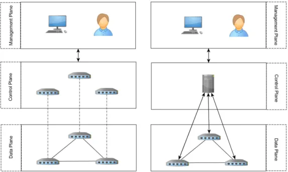
As shown on Figure 1.1, the network can be divided into three different planes: the management plane, the control plane, and the data plane. In the first plane we have
2 Chapter 1. Introduction
management applications used by engineers for motorization and configuration of the network. The control plane represents the network protocols defined by the management plane. This plane controls the data plane defining how it should behave according with the rules imposed by the management plane. The data plane is responsible for forwarding the data. In current networks the control plane and the data plane are handled by the same network devices and the whole structure is highly decentralized, which means, operations such adding a new protocol must be deployed in every network component. Although this architecture has been quite effective in terms of network performance, the difficulty to add new features led to the addition a plethora of devices such as: dispatchers, man-agement middleboxes, firewalls, etc, increasing the network cost and complexity, and as a consequence making its management more difficult.
Figure 1.1: Traditional Networks Architecture
1.2
Software Defined Network, a new paradigm
Software-Defined Networking (SDN) is a new paradigm in networks. The main idea of SDN consists in the centralization of network control in a logically centralized program – the SDN controller – which controls and monitors the behavior of the network. With this program it is possible to control and manage the entire network by writing applications that run on top of it. By separating the control plane from the data plane, it becomes easier to configure the network. Networks thus become programmable, allowing the definition
Chapter 1. Introduction 3
of the behavior of the entire network from the controller, and the possibility to easily cre-ate advanced network policies, such as load balancing. Figure 1.2 presents the difference between traditional networks and Software-Defined Networks, where in the first the con-trol plane is handle by the multiple network devices, while in SDNs the concon-trol plane in handle by software controller hosted in a server or a cluster of servers.
Figure 1.2: Traditional Network (left) vs SDN (right)
1.3
Motivation
To achieve better performance internet services are replicated, with load balancers dis-tributing work by the replicas. The common architecture consists in putting a hardware-based load balancer - a dispatcher - at the entrance of the network. This dispatcher uses load balancing algorithms such as simple Round-Robin or more sophisticated content-based algorithms, to distribute the load by the several replicas of the server. Since all the requests must go through the dispatcher, this component may become a bottleneck, so usually it is necessary to replicate the dispatcher too. This method can be costly, ranging from around $2,000 to close to hundreds of thousands of dollars[3]. Motivated by this fact, in this work we investigate the possibility of building a load balancer as a software application in an SDN infrastructure. This solution is cheaper because it is software based and the application runs in the server that hosts the controler. In addition, it may achieve better performance because it becomes possible to not only choose which server handles
4 Chapter 1. Introduction
1.4
Contributions
We will evaluate the combination of both server and path selection algorithms to un-derstand which algorithms have a better performance. As we anticipate that no single algorithm has the best performance in every situation, we propose MALOB, a Multi-Algorithm Load Balancer that has the capability of adapting according to the type of request, and choosing the algorithm that fits better to the current request. Using the ben-efits of the SDN paradigm this load balancer takes into account different variables such as link latency, link bandwidth, and CPU usage. The source code was made available open-source on GitHub1.
For evaluation, we used the Global Environment for Network Innovations (GENI) [13], a large-scale testbed that enables us to perform the evaluation in a realistic non-structured Wide Area Network (WAN) environment. Using GENI we are able to obtain more realis-tic results about the impact of our solution in real Software Defined Networks.
As a summary, the main contributions of our work are:
• Multi-Algorithm Load Balancer (MALOB), an adaptable load balancer application for the Floodlight [8] controller;
• An evaluation of different kinds of load balancing algorithms for server selection and path selection;
• Evaluation of the load balancing algorithms on an non-structured WAN network using GENI [13], a large scale testbed.
1.5
Work Plan
In this section we present our work plan, the challenges we faced and the required changes to the initial plan.
Study of the State of the Art
Between October and January, we focused on studying the state of the art. By reading some literature about SDN, we learned how the separation of the control plane from the data plane may bring benefit to the current state of affairs in networking. We have noticed that most of the evaluation of SDN applications is made by using the Mininet emulator (which will be explained later) and, due the lack of experiments using large scale test beds, we decided to use GENI, a large testbed that enabled us to create a real network with multiple machines, aiming to obtain a more accurate view of the performance of our application.
Chapter 1. Introduction 5
Familiarization with the Floodlight controller
During the following two months, we experimented using the SDN controller on Mininet. After some research we were able to create a network on Mininet, which allowed us to start learning how the controller works. For that we focused on creating different load balancing algorithms.
Familiarization with the GENI Testbed
From April until the end of May, we studied the possibility of using this platform for evaluation. At the end of May we built our non-structured WAN topology and started running the first algorithms developed.
Selection and Implementation of the Algorithms
We started discussing the algorithms that were worth a deeper evaluation. After an anal-ysis of possible alternatives, we decided to evaluate three algorithms for path selection, and three algorithms server selection. We finished the implementation of all algorithms by the end of July.
Test and evaluation using GENI
The tests ran on GENI until the end of August. We tested the algorithms considering three different types of requests, since we anticipated that some algorithms would perform bet-ter than others, depending on the type of request. First, for simple Hypertext Transfer Protocol (HTTP) requests, the latency on the path is the variable that has the most im-pact, since it is dealing with small files. Then, we moved to File Transfer Protocol (FTP) requests because the transfer of large files implies that the chosen path should have the highest throughput possible. Finally, we considered an application for genome data pro-cessing, motivated by the need of having an application that requires more processing time from the servers. In this case, unlike the other two, it is not the time to transfer that matters, but the response time of the server.
Differences from the initial plan
During the course of this project we realized that performing an evaluation using a real test bed is an arduous task. The main change to the initial plan occurred while creating the topology using the GENI platform. We tried both the ExoGENI and the InstaGENI designs, which took some time because the resources were not always accessible. Since the network crosses the entire United States, it was susceptible to a series of problems. Just to give an example of the realism of our evaluation setting, on one occasion one site
6 Chapter 1. Introduction
1.6
Document Structure
This document is organized as follows:
• Chapter 2 – Gives a review of related work. We present the state of the art on SDN and load balancing. We explain how SDN operates and some of its key functions. We also present various load balancing algorithms. Finally, we discuss several possibilities for evaluating network experiments.
• Chapter 3 - Describes the design of our load balancing application explaining its architecture and how we implemented it.
• Chapter 4 - Describes the setup used to test our algorithms, and the results of our experiments.
Chapter 2
Related Work
In this section we will explain the SDN paradigm and how future networks may benefit from this novel architecture. We give an overview on load balancing algorithms, and conclude with a summary of the evaluation platforms that are used in our work.
2.1
Software-Defined Networking
Software-Defined Networking (SDN) [19, 27] is a new paradigm in networks. The main idea of SDN consists in the centralization of network control in a logically centralized program – the SDN controller – which controls and monitors the behavior of the network. The goal is to separate the control plane from the data plane. This separation is possible by means of an Application Programming Interface (API) between the switches and the controller, such as OpenFlow [30]. Networks thus become programmable, allowing the definition of the behavior of the entire network from the controller and the possibility to create advanced network policies such as load balancing, routing and security.
Figure 2.1 illustrates the various layers that constitute an SDN. The first layer, called application layer, consists of the applications that define the behavior of the network, com-monly using the Representational State Transfer API [18]. This API uses the Hypertext Transfer Protocol (HTTP) to allow remote applications to send instructions to the con-troller or retrieve information from the concon-troller. In the control layer we have a logically centralized software-based SDN controller, responsible for handling the control plane and maintain a global view of the network. This controller has the job of translating the appli-cations instructions to the data layer by means of the OpenFlow API. It is also responsible to give applications an up-to-date view of the network state. The data layer is composed of the network devices responsible for packet forwarding, such as switches and routers. The communication between the data layer and the control layer is made by OpenFlow.
8 Chapter 2. Related Work
Figure 2.1: Network design using SDN
2.1.1
OpenFlow
OpenFlow [30] is a protocol that enables the communication between the switches and the SDN controller. OpenFlow started as a mechanism for researchers to realistically evaluate their experiments, as it enables the separation of experimental traffic from production traffic. This allows the use of a network switch for experiments without interfering with normal traffic. OpenFlow allows the modification of the flow tables of the switches, using a well-defined interface, by issuing commands from the controller. An OpenFlow-enabled switch (OF switch) can match packets against the different headers which enable more dynamic and flexible forwarding instructions than common network devices.
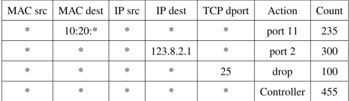
In Table 2.1 we illustrate a flow table that supports OpenFlow. The table shows the flow rules used to evaluate what action the switch should take when a packet for that par-ticular flow arrives. The first 5 columns represent the packet headers that can be matched (this is what defines a flow). The column “Action” represents the action, defined by the controller, that the switch must perform when it matches on that row. Finally the last column represents the number of packets received by the switch that matched that flow. For example, we can see that all packages with Transmission Control Protocol (TCP) des-tination port 25 will be discarded and that the switch has already discarded 100 of those packets. The unknown packets (all the first 5 columns have only an *) are forwarded to
Chapter 2. Related Work 9
the controller, which is the default behavior, the controller can then decide what action to perform to those packets.
MAC src MAC dest IP src IP dest TCP dport Action Count * 10:20:* * * * port 11 235 * * * 123.8.2.1 * port 2 300
* * * * 25 drop 100
* * * * * Controller 455
Table 2.1: Example of an OF-enabled switch flow table
2.2
SDN controllers
Controllers are the core component of an SDN. They oversee the behavior of the entire network and implement the decisions to achieve the desired state for the network. They are a logically centralized program that offers services and applications for controlling the network. It is important to emphasize that a logically centralized program does not mean that we have a centralized system. Actually, the controller can be distributed and replicated for fault tolerance and/or better performance [26]. In any case, applications are written as if the network view was stored on a single machine [21].
2.2.1
Nox
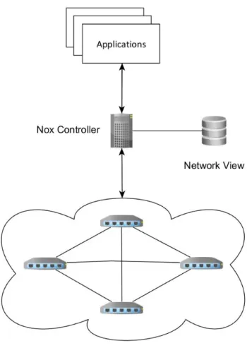
NOX [21] was the first SDN controller and was written in C++ and Python. As shown in Figure 2.2, a NOX-based network consists of a set of switches and one server, running the NOX controller software and the management applications over it. The NOX programing model is event-driven, meaning that, the data plane triggers events, like a Packet In event, and applications are notified of the event. NOX has core applications to discover and observe the network components. These applications are responsible for creating and updating a single database containing all network observations and data (network view), providing observation granularity at the switch-level topology, showing the locations of users, hosts, middleboxes, and other network elements [21]. Like any other centralized controller, Nox has to handle all flows in the network making it a possible bottleneck. Anyway this controller is able to handle around 100000 flows per second [21], which is considered enough for a good range of networks [15].
2.2.2
Onix
10 Chapter 2. Related Work
Figure 2.2: NOX-based network
called Network Information Base (NIB) that stores the current state of the network. The state in the NIB is distributed and replicated among all Onix instances using basic state distribution primitives. Onix also provides a general API which allows, depending on the desired implementation, to make trade-offs among consistency, durability, and scalability.
Contrary to other controller designs, the NIB sits between the management plane and the control plane, and it is through this database that the applications interact indirectly with the data plane. The management plane modifies the NIB and the controller reads those modifications and translates them in commands to the data plane. In the other way around, the controller updates the NIB according to the events triggered by the data plane, and notifies the applications about the updates made in the NIB. Every time a NIB is modified, the NIBs of the other Onix instances must be updated, for the sake of consistency. Onix provides the possibility of choosing between strong or eventual consistency for this purpose. For strong consistency it offers a transactional persistent database, and for eventual consistency it has a memory based Distributed Hash Table (DHT) available.
Chapter 2. Related Work 11
2.2.3
Floodlight
Floodlight [8] is an enterprise-class, Apache-licensed, Java-based OpenFlow Controller. This is the one we have chosen to use in our project because it is designed to offer high-performance and scales well with the number of network components [8]. The fact that it is implemented in Java also contributed to this decision.
The Floodlight controller is based on another controller called Beacon [17]. Java was the chosen programming language because it offers the best balance between performance and user friendliness. It is also portable, which means it can run on a variety of operative systems. In addition, Beacon (and Floodlight) has a good and simple API and comes with useful applications:
• Device manager: tracks devices seen in the network including information on their addresses, last seen date, and the switch and port last seen on;
• Topology: discovers links between connected OpenFlow switches;
• Routing: provides shortest path layer-2 routing between devices in the network; • Web: provides a Web user interface.
One advantage of Beacon and Floodlight is the runtime modularity, the capability of not only starting and stoping applications while it is running, but to also add and remove them, without shutting down the controller process. Applications are fully multithreaded having blocking (Shared Queue) and non-blocking (Run-to-completion) algorithms for reading OpenFlow Messages. The evaluation presented in [17] concluded that Beacon was the controller with best performance when compared to NOX [21], Pox [5] and Mae-stro [32].
2.3
Load Balancing
Web applications scale by running on multiple servers to be able to service an increasing number of users that demand Web content. To achieve the desired performance, load balancers are used to distribute the request by the replicas. This results in important benefits such as scalability, availability, manageability, and security of Web sites [20]. The Load balancer job is to choose which server should handle the next request, using algorithms such as Round-Robin. After receiving a request from the client, it applies the load balancing algorithm and forwards the request to the chosen server.
Load Balancers today consist of expensive specialized hardware, the dispatcher, lo-cated at the entrance of the network [37]. This dispatcher is a special component used only for load balancing so it can handle many requests with good performance. The
12 Chapter 2. Related Work
balancer, which increases the cost of the solution further. A limitation of the traditional load balancers is that they only take into account server choice, not taking into consid-eration the traffic load. This limitation is something we explore in our work by creating algorithms that evaluate the state of the links, taking into consideration not only server choice itself, but also taking into consideration the best path to the chosen server.
2.3.1
Content-blind load balancing
The first category of load balancer is called Content-blind load balancing [20]. This type of load balancer is unaware of the application information contained in the incoming re-quest. These load balancers can work at layer-2 or layer-3. In a layer-2 forwarding mode, both the load balancer and the servers are in the same Internet Protocol (IP) subnet. The load balancer uses the Media Access Control (MAC) address available in the data link layer information to determine the output interface port for that packet, after running the load balancer algorithm. In layer-3 forwarding, the load balancer and servers have dif-ferent IP addresses and in this case the load balancer works as a router. Two forwarding techniques have been implemented in a dispatcher-based web cluster using layer-3 rout-ing: Network Address Translation (NAT) and IP Tunneling (IPTun). The first one consists of rewriting the layer-3 destination address of the incoming packet to the IP address of the real server selected by the load balancer. IPTun consists of the encapsulation of IP datagrams within IP datagrams, with the source and destination IP address specifying the virtual IP address of the system and the target server IP address, respectively. The Vir-tual Internet Protocol (VIP) is an IP address assigned to multiple applications residing on multiple servers, rather than being assigned to a specific server or network interface card. Incoming data packets are sent to the VIP address and routed to actual network interfaces using the MAC address.
In this type of load balancers, the most common algorithms used for forwarding pack-ets are:
• Round Robin: the load balancer chooses the next server in a circular way;
• Random: the load balancer chooses the next server randomly;
• Least Loaded: the Load balancer chooses the server with the lowest load;
• Least Connections: the Load balancer chooses the server with smallest number of TCP connections.
2.3.2
Content-aware load balancing
Content-aware load balancing [20] is a category of load balancers where the load balancer is aware of the packet’s content data. In this architecture each server may provide a
Chapter 2. Related Work 13
different service but the client does not know the specific machine that provides it with the service. It is the load balancer’s job to forward each package to the correct server. For this, the load balancer analyses the package content (HTTP request). This is thus an architecture that works at the application level. One big advantage of this approach is the possibility to use caching techniques on the servers. Applications can store frequent replies in cache, making more efficient the processing of the following requests. Example architectures include: TCP Splicing [29], Redirect Flows [16], Socket Cloning [38].
2.3.3
Plug-n-Serve: An SDN Load Balancer
Part of our interest in this problem has arisen from Plug-n-Serve [24]. The motivation of Plug-n-Serve is to transform load balancing into a network primitive. As an SDN load balancer, it benefits from the SDN architecture where a logically centralized controller handles the control plane. The load balancer application uses this controller to configure the data plane in accordance with the application decisions. The algorithm used in this load balancer is called LOBUS (Load-Balancing over UnStructured networks). The state LOBUS needs to track, includes the load on the servers, the response time of the servers and the congestion of the links. The algorithm determines the current state of the network and servers and, then, based on this information, chooses the appropriate server to handle the request and chooses the best path in order to minimize response times.
On Figure 2.3 (taken from [24]), we have a diagram that shows the Plug-n-Serve design.
The controller has three modules: Flow manager, Net Manager, and Host Manager. The Net Manager is responsible to oversee network behavior, topology, and utilization levels. This is used to gather useful information for the application to be able to choose the best path. The Host Manager monitors the state and load of the network servers. This component gathers information like the host CPU usage or the number of TCP connec-tions, which allows the application to choose the server that, should handle the request. The Flow Manager manages route flows according to the load balancing application. It is also responsible to inform the application when a new flow arrives on a switch.
Plug-n-Serve follows the design of Aster*x [22], a prototype that was created to initi-ate a meaningful debiniti-ate on designing load-balancing systems for large-scale services. We believe the idea behind Aster*x and Plug-n-Serve is solid, but both short papers (a poster and a demo) do not detail the algorithms they introduced, and they do not compare with other alternatives. The present work aims to fulfill those gaps.
2.4
Evaluation
14 Chapter 2. Related Work
Figure 2.3: Plug-n-Serve design (Source: [24])
2.4.1
Mininet
Mininet [28] is an emulator written in python that allows the evaluation of a network with several components in a single computer. Mininet differs from other emulators because it employs lightweight virtualization (by using Linux containers) and supports the SDN paradigm. It can run real code and support several topologies. This emulator has some limitations, namely the precision of the results with high loads, which may not be accu-rate. The CPU resources are multiplexed in time, and for that reason the Linux scheduler does not guarantee that a component that is ready to send a packet, to do so.
2.4.2
Mininet Hi-Fi
Mininet Hi-Fi [23] extends the original Mininet architecture by adding mechanisms for performance isolation, resource provisioning, and monitoring for performance fidelity. This version overcomes the limitations of its predecessor, isolating the resources used by virtual hosts and switches. For that purpose Mininet Hi-Fi uses the following OS-level features from Linux:
Chapter 2. Related Work 15
host) to be treated as a single entity for scheduling and resource management; • CPU Bandwidth, enforces a maximum time quota for a cgroup within a given period
of time;
• Traffic Control, configures link properties such as bandwidth, delay, and packet loss.
In this way, resources are carefully provisioned by splitting the CPU among containers and leaving some margin to handle packet forwarding, based on offline profiling, thus yielding a result that matches hardware.
Mininet-HiFi lets the experimenter allocate link speeds, topologies, and CPU fractions based on their estimated demand, and can also monitor performance fidelity to help verify that an experiment is operating realistically. As links run at a fixed-rate, packets should leave at predictable times whenever the queue is non-empty. To monitor host fidelity, the CPU idle time is observed. CPU bandwidth limiting ensures that no virtual host receives excessive CPU time, but it can happen that a virtual host does not receive sufficient time to execute its workload. Nevertheless, Mininet Hi-Fi is a very useful tool to evaluate networks with good fidelity.
2.4.3
GENI
Although Mininet-Hi-Fi provides mechanisms for performance isolation, it is still an eval-uation platform that does not represent real hardware or real users. In this study our goal was to evaluate our ideas in a real SDN. For that reason, we decided to use the Global Environments for Network Innovations (GENI) [13]. GENI is a virtual laboratory test bed for large-scale network experimentation where researchers can create their net-work topologies using real equipment. In general, test beds like GENI are platforms that enable the possibility of deployment and evaluation of large, realistic experiments with real hardware and real users. This development environment provides customizable soft-ware, hardsoft-ware, and networking components for researchers to create their experiments. GENI’s original motivation was to overcome the limitations imposed by the current net-work infrastructures that severely limit the potential for innovation in the global, public Internet. GENI also explores the potential of emerging technologies such as SDN. Virtu-alization enables experimentation to run at reasonable cost, so GENI uses it to combine heterogeneous resource types, providing a platform for network science researchers to perform experiments that move beyond simulation. GENI also provides:
• Scalability: experiments can range from small laboratory to a national scale;
16 Chapter 2. Related Work
• Execution environment diversity, ranging from isolated laboratory style controlled environments to internet environments.
In order to support a large range of users, resources must be shared while giving the impression that those resources are exclusive. GENI borrows the concept of sliceabil-ity [33], the virtualization of a shared physical resource into multiple virtual machines providing some degree of isolation and the illusion of exclusive resources. Similarly, network resources can be also virtualized. The most common way to achieve this is by means of virtual local area networks (VLANs) that provide a well-understood degree of data isolation. However, VLANs do not offer meaningful performance isolation or pro-grammatic control. For the latter, the SDN paradigm offers a more flexible means for network virtualization.
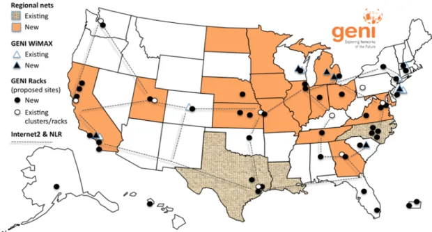
The GENI network sites are mainly composed of university campus in the United States, as shown in Figure 2.4. Each site has a chief information officer (CIO) that is re-sponsible for the maintenance and accessibility of the site. In order to achieve that support from each site’s CIO, GENI organized a program to educate universities on the potential benefits to their campus of emerging paradigms like SDN. Because this technology of-fers the possibility of supporting enhanced campus network management capabilities as well as enabling more effective and cost-effective approaches to network security, over fifty universities joined this program. A key goal of GENI’s current expansion phase is to achieve initial deployments of this technology in parallel with production networks at national scale. This deployment will result in a revolutionary new programmable, virtual-ized, distributed collection of resources (networks, computers and storage), a global scale deeply programmable cloudthat will support the GENI research mission, and as well as enabling research and education in a wide variety of areas such as big data, cloud-based applications, or security.
As a summary, using GENI brings the following benefits:
• Amount and diversity of resources: GENI provides more resources than other test beds or laboratories for network experimentation. It gives access to hundreds of nation-wide distributed resources including computation and network;
• Realistic networks: GENI permits a growing number of experiments to move be-yond simulation and into emulation and realistic deployment environments;
• Non-IP connectivity across resources: GENI allows users to set up Layer 2 connec-tions between compute resources and run Layer 3 and above protocols connecting these resources;
• Deep programmability: using the SDN paradigm, GENI gives the possibility to program not only the hosts but also the switches of the network;
Chapter 2. Related Work 17
Figure 2.4: Map with all GENI sites. (Source: www.geni.net)
• Control the experiment’s environment: we can get exclusive access to certain re-sources like CPU, RAM and network rere-sources, and hence the ability to repeat experiments under similar conditions.
InstaGENI
In each campus, the basic deployment unit of computation and storage is called a GENI rack. Each rack has multiple compute nodes, disk-based persistent storage, and Open-Flow switches. At the moment two distinct GENI rack types exist, ExoGENI [10] and InstaGENI [12]. The first was built by the Renaissance Computing Institute, emphasizing performance using IBM hardware. The second was built by an HP team, emphasizing affordability using HP hardware. The InstaGENI design was the chosen for our project mainly because it provided us with more sites and a better geographical dispersion than ExoGENI. In figure 2.5 we show the location of the InstaGENI sites.
Each InstaGENI rack consists of five experiment nodes, one control node, an Open-Flow switch for internal routing, and data plane connectivity to the Internet. In our work the experimental nodes used Xen virtualization [11]. This virtualization platform allows multiple operating systems to share conventional hardware in a safe and resource man-aged fashion, but without sacrificing either performance or functionality. Also, one of the images hosted on Xen nodes supports Open vSwitch (OVS)) [34]. OVS is an open-source software switch designed to be used as a virtual switch in virtualized server environments that supports OpenFlow. With this software virtual machines can forward traffic between different Virtual Machines (VMs) on the same physical host and also forward traffic
be-18 Chapter 2. Related Work
Figure 2.5: Map with all InstaGENI sites
across the wide area, while permitting deep programmability. Various techniques can be used for that purpose. In our projected we used Ethernet-over-GRE (EGRE) Tunnels, an IP tunneling technique where packets are multiplexed based on an Ethernet frame’s des-tination MAC address instead of IP addresses, avoiding the IP-address collisions that can happen in this type of environment.
Chapter 3
Design and Implementation
The load balancing application developed in this thesis was built on top of the floodlight controller, which controls all OpenFlow switches on the network, as shown in Figure 3.1. Our application is an extension of floodlight’s simple load balancer, that currently only uses the round-robin algorithm for choosing the server for the next request, and the shortest path (by number of hops) for selecting the path to the server. We use these algorithms as baseline.
20 Chapter 3. Design and Implementation
3.1
Application Design
Three key primitives must be defined for our application to work: Virtual IPs (VIPs), poolsand members. VIP is the virtual IP of the service that clients use to make requests. This is the IP clients use when making a request to the service. They are unaware that this is VIP or that the service is replicated. When a new request is sent, it arrives at the first edge switch and, as it is the first packet of this flow, it is forwarded to the controller. When it arrives at the controller, the application checks the destination IP. If it is a VIP, the application runs the load balancing algorithm and selects the target server and the path to reach it. The controller, using the information from the application, creates the necessary entries in the switch flow tables and pushes them into the data plane. In Figure 3.2 we have an example of this process. We will return to this figure below. Pool is the list of servers that correspond to a certain VIP. It is from this list that the algorithm selects the target server. Finally, a member represents a server in a pool’s list. This primitive has important attributes that define the state of the represented server, such as the CPU usage, the number of TCP connections, or the response time. These are used by some of the algorithms to select the next server.
Using floodlight’s Representational State Transfer (REST) API [6, 18], we can easily define these primitives, as in Table 3.1. For example in the REST command to define a VIP, five data fields are presented: the “id”, identifier of the VIP; the “name”, name of the VIP; the “protocol” and “port”, optional fields used for example if the design requires different VIPs to handle different protocols; the “address”, the VIP address; and finally the url with the address of the controller were the data is posted.
Primitive REST Command
VIP curl -X POST -d ’{“id”:“1”,“name”:“vip1”,“protocol”:“icmp”,“address”: “10.0.0.100”,“port”:“8”}’ http://< ControllerIP >/quantum/v1.0/vips/ Pool curl -X POST -d ’{“id”:“1”,“name”:“pool1”,“protocol”:“icmp”,“vip id”:
“1”}’ http://< ControllerIP >/quantum /v1.0/pools/
Member curl -X POST -d ’{“id”:“2”,“address”:“10.0.0.4”,“port”:“8”,“pool id”: “1”}’ http://< ControllerIP >/quantum/v1.0/members/
Table 3.1: REST Commands to define important application primitives
Considering Figure 3.2, in the first step the client makes a request to the service’s VIP. Then (step two), the switch realizes that it does not have any flow in its table for this new packet, so it sends that packet to the controller using the OpenFlow protocol, triggering a PacketIn event at the controller (step 2). Upon receiving the new packet, the controller informs the load balancing application about the event (step 3). The application checks if the Destination IP of the packet matches any of its VIPs, if so, the application runs the
Chapter 3. Design and Implementation 21
Figure 3.2: Steps for a new request
load balancing algorithm to choose the destination server and the path to reach it (step 4). From the results of the algorithm the application tells the controller to start a PacketOut event to the chosen server using the selected path (step 5). Note that the application chooses a path for the request and for the corresponding reply. So, on the sixth step, the controller pushes the new flows into the necessary switches to enforce the paths indicated by the application. Since we are using a VIP in step 6.1, special actions are needed. While in steps 6.2 and 6.3 the action is to tell the switch to which port the packets of this flow should go, in step 6.1 the switch will also have to convert the destination IP (VIP) into the chosen server IP, and then in the backward direction to convert again from the server IP into the VIP for the reply. The same is true for the MAC address. Finally, the controller pushes back the first packet with the new destination IP to the switch. Since all switches have the necessary flows on their tables, the request (and the reply) can travel throughout
22 Chapter 3. Design and Implementation
3.2
MALOB
Different applications have different requirements. A web browsing application requires short response times, whereas for a large file transfer, high throughput is preferable. For that reason, different service requests may benefit from distinct load balancing algorithms. In light of that, we created MALOB, a Multi-Algorithm Load Balancer that has the capa-bility to adapt to the different types of requests. In the design of MALOB we considered three broad types of requests. First requests that prefer short response time. For these, the load balancer should choose the path with the lowest latency (Web browsing applica-tions is the prime example). Second one that perfers the path with the highest throughput (file transfer applications, for instance). Finally, one that requires a significant amount of processing (say a, genome processing application). The first is used when clients request relatively small data with high intensity but requiring insignificant processing. HTTP re-quests are an example of such: the response to the HTTP GET request must be returned as quickly as possible, since pages are very small, making latency the prime factor to con-sider. The second one is a request for a larger amount of data. Downloading files using protocols such as FTP are an example of this type of request where the throughput a path can offer is the variable with highest impact on the download time. In the last type of application we consider, requests require a significant processing. For these applications, path latency or throughput do not have a great impact and choosing the server with highest available CPU is the most important factor.
Figure 3.3: MALOB usage
Considering this, upon receiving a new request MALOB analyses the destination port of the request, checks its services table (Table 3.2) and decides which algorithm fits better that type of request. For example, as can be seen in Figure 3.3, when the application receives a request with destination port 80, the port used by HTTP requests, the load
Chapter 3. Design and Implementation 23
balancer uses the shortest path-latency server algorithm. As the name hints, this algorithm selects the server whose path offers the lowest latency. If, on the other hand, the request is for port 21, used by FTP, the server chosen is the one whose path offers the highest throughput. The third example port we have is for a bioinformatics application, which requires a huge amount of processing. In this case, the load balancer uses the algorithm that chooses the server with lowest CPU usage. To set up the MALOB service table (Table 3.2) we used floodlight’s Rest API to define new services that use predefined ports, and the algorithm that will be used for those requests. An example of one such command is:
• curl –x POST –d ’{“service name”:“BioApp ”,“algorithm”:“3”,“port”:“6789”}’ http://< ControllerIP >/quantum/v1.0/services/
One advantage of using the REST API is that we can modify the service table in runtime, without the need to stop and reset the controller.
Service Name Port Algorithm
HTTP 80 1
FTP 21 2
BioApp 6789 3 Default - 1
Table 3.2: MALOB Services Table. In the last colum we present the algorithm identifiers: 1 - Shortest Latency-Path Server; 2 - Highest Throughput-Path Server; 3 - Lowest CPU Usage.
3.3
Implementation
This section presents the implementation details. We include a description of the modi-fications made to two of the controller’s default applications: the original Load Balancer application and the Link Discovery application. We also describe all the load balancing algorithms evaluated in this thesis, and how they were implemented.
3.3.1
Maintaining Network State
The SDN paradigm allows us to have a global view of the entire network from a logically centralized location, giving us the possibility to take into account several variables about network state, such as the link’s latency and bandwidth, thus allowing us to create more advanced routing algorithms. In this section we explain how the SDN controller keeps
24 Chapter 3. Design and Implementation
Network Latency
One load balancing algorithm takes path latency into account, so we need to keep track of this latency between every pair of links. For this purpose, we leverage on an application built on top of floodlight: Link Discovery. This application is used by the controller to discover the topology. Using this application the controller is able to discover the links between OF switches. This application, periodically commands OF switches to flood Link Layer Discover Protocol (LLDP) packets and Broadcast Domain Discovery Protocol (BDDP)1packets through all their ports in order to build a view of the whole topology. The LLDP packets are not forwarded by the switches. When a switch receives one of these packets from another switch it sends it to the controller. This way one LLDP packet only travels between two directly connected switches, making it possible to calculate the latency of every link.
To calculate the latency between two OF switches, we calculate the round trip of the LLDP packets. As the controller-switch link delay influences the overall round trip (particularly in the WAN setting we are considering), we need to perform a correction on the estimated value.
Figure 3.4: Total round-trip time of a LLDP packet
Consider Figure 3.4 to understand why. The total round trip time of a LLDP packet (RT TT otal) is influenced by three variables: latency between S1and the controller (LS1−C),
the latency between S1 and S2 (LS1−S2) and the latency between S2 and the controller
(LS2−C). Since we only need the latency between switches S1 and S2, we have to
elimi-nate the other two variables. To that end, when the controller starts the discovery process (floodlight has a 15 seconds interval between discoveries), it also sends an ECHO REQUEST OF message to each switch. Every time a switch receives an ECHO REQUEST it replies
Chapter 3. Design and Implementation 25
with an ECHO REPLY. By calculating the time it takes for these packets to travel between the switch and the controller, we are able to obtain an approximate measure for those two variables we want to eliminate. As a result, we obtain the latency between S1and S2:
LS1−S2 = RT TT otal − ( RT TLS
1−C+RT TLS2−C
2 )
Network Throughput
One of the algorithms evaluated uses the throughput of the paths to determine the best path. To measure the throughput in each link of the network we use the tool Iperf [41]. Iperf measures maximum TCP throughput between two hosts. Iperf reports throughput, delay, jitter and datagram loss between two nodes. This tool was installed on every node of the network and, by means of a script, it was periodically executed between every pair of directly connected nodes. To send the throughput information collected by the nodes to the controller, we devised the following technique presented in Figure 3.5.
When the script running iperf on a node finishes collecting the throughput information, a UDP packet that contains the information collected is sent with a special IP that does not belong to any server or client. When the packet arrives at the first OF switch it realizes that it does not have any entry in its flow table that matches the packet, so it sends it to the controller. The controller, upon receiving the packet sent by the OF switch, analyzes the destination IP of the packet and realizes that the packet contains information about the throughput of a link between two directly connected nodes. In order for the controller to be able to update its information, it needs the IP of the nodes at each end of the link and the throughout value of the link. The IP of one of the nodes is the IP of the sender of the packet, the other two values are retrieved from the data of the packet. Finally, the controller discards the packet.
26 Chapter 3. Design and Implementation
3.3.2
Maintaining Server State
In this thesis we use two variables to define the state of the servers: CPU usage and the number of active TCP connections. A script was developed to retrieve this data for every server. The technique used to send this information to the controller is the same as for the throughput above. Next we describe how the script is used to obtain those two variables.
CPU Usage
Using the ımpstat command from the sysstat package, the script is able to retrieve CPU reports that include this information. This command has two arguments; the first argument is the time interval between reports while the second is the number of reports, calculating in the end the average value between reports.
Number of TCP Connections
To retrieve the number of TCP connections, the load balancer application increments a counter that represents the number of active TCP connections of one server, every time that server is chosen. Since it would be time-consuming for the controller to control when a connection ends, we use an additional technique to refresh this counter. A script on the servers runs the command netstat −an|grep “server IP” |grep -c “ESTABLISHED”, to periodically retrieve the number of active TCP connections on that server. Hence the number of TCP connections is periodically updated in the application. The use of the counter and its periodic refresh is important when multiple requests are in a queue waiting for the load balancer to chose the server that will handle the next request. Without the refresh all the request in the queue would be sent to the same server until the update from the servers arrived which would not be effective.
3.3.3
Load Balancing Algorithms
In this section we make a detailed description of the load balancing algorithms that were evaluated.
Algorithms for Path Selection
In an SDN, we have the possibility of controlling the path’s every flow follows in the network. Therefore, after selecting the server, it is possible to select the best path for that server. To choose the best path, we evaluated two versions of the shortest path algorithm, and a new algorithm that selects the path that provides the highest throughput:
• Shortest Path by number of Hops (SPH): the chosen path is the one with the least number of hops between the client and the server. This is the algorithm used in conventional networks.
Chapter 3. Design and Implementation 27
• Shortest Path by Latency (SPL): the chosen path is the one with the lowest latency. This latency is the sum of the latency on each link of the route (set of links) between the server and the client.
• Highest Throughput Path (HTP): the selected path is the one that has the highest available throughput. The throughput is the amount of data that the link can transmit per second. Note that the best path is the one with highest throughput in the least throughput link. To make this point absolutely clear in Figure 3.6 we illustrate a toy example. In this figure we have two paths, each composed of two links: path 1 has an 80 Mb/s link and another of 10 Mb/s, while path 2 has two links with 20 Mb/s throughput each. Despite path 1 having the best link (80 Mb/s), the best path is the second one, as its least throughput link is the 20 Mb/s, which compares favorably to the 10 Mb/s for path 1.
Figure 3.6: Paths bandwidth example
The first algorithm is the one used by the current floodlight’s load balancer application. It uses the Dijkstra’s algorithm [40] for selecting the path using the least number of hops. For the second algorithm, we changed the Dijkstra’s algorithm in such a way to use the latency between nodes, as the variable, instead of the number of hops. The third algorithm is not a variation of the Dijkstra’s algorithm. When a new request arrives, the algorithm calculates the maximum throughput in each possible path to the target server, and selects the one with the highest value.
Algorithms for Server Selection
28 Chapter 3. Design and Implementation
• Round-Robin (RR): this is the most common load balancing algorithm, it simply chooses the next server in a circular way. Being one of the most common and widely used, it will be employed as a baseline.
• Least Number of TCP Connections (LC): this algorithm chooses the server with the least number of active TCP connections.
• Least CPU Usage (CPU): in this algorithm, the server with lowest CPU usage is chosen.
SDN-Based Server Selection Algorithms
With SDN we are more aware of the state of the network, so we can use different variables to evaluate the best load balancing solution. Using the potential this paradigm has to offer, we developed two new algorithms. The main difference between these two SDN-based algorithms and the traditional ones is that the selection of the server depends on the path. In traditional algorithms the server is chosen based on server conditions (CPU usage, number od connections, etc., as seen before).
• Shortest Latency-Path Server (SL-PS): chooses the server whose path between itself and the client offers the lowest latency.
• Highest Throughput-Path Server (HT-PS): chooses the server whose path between itself and the client has the best throughput.
The first algorithm calculates the lowest latency routes between the client and all servers. It is similar to the SPL algorithm, but the calculation is made to all servers. After having the set of lowest latency routes to each server, the algorithm chooses the server with the lowest latency route of the set. In a WAN environment this will normally be the server closest to the client. The HT-PS algorithm is similar, but instead of finding the lowest latency path, it finds the best throughput path to all servers.
Chapter 4
Evaluation
The main objective of our evaluation is to assess the impact of a load balancer based on the SDN paradigm in real networks. To this end, we will run our experiment in the Global Environments for Network Innovations (GENI) [13]. As said before, GENI is a virtual laboratory for large-scale networks experimentation where researchers can create their network topologies with real equipment and evaluate them with real usage. The target of our evaluation is a WAN environment. We evaluated different combinations of algorithms for server and path selection and compared their performance considering three types of requests: HTTP requests, a large file transfer, and a CPU-heavy application related to genome data processing.
We considered the algorithms described in Section 3.3.3. A summary of all combina-tions that were tested appears in Table 4.1.
Shortest Path Hops Shortest Path Latency Highest Throughput Path Round-Robin RR+SPH RR+SPL RR+HTP
#Connections LC+SPH LC+SPL LC+HTP CPU Usage CPU+SPH CPU+SPL CPU+HTP
Shortest Latency-Path Server (SL-PS) Highest Throughput-Path Server (HT-PS)
Table 4.1: Algorithm combinations formed by server choice algorithms (rows) and path choice algorithms (columns)
4.1
Topology and Testbed Setup
Using GENI resources we were able to create a non-structured WAN across the United States, as show on Figure 4.1. The nodes on the network are virtual machines with the
30 Chapter 4. Evaluation
characteristics presented in Table 4.2. The virtual machines that work as a switch have Open vSwitch [34, 7] installed.
Table 4.3, displays a snapshot of the throughput and latency of the links on this setup. This table shows that exists heterogeneity in this network, with links with 90 Mb/s of throughput while others only have 12 Mb/s. The same goes for the latency that ranges from 2 ms to 36 ms. This heterogeneity is very important in order to achieve realistic and representative results in our evaluation.
Figure 4.1: Network Topology
Nodes #CPU GHz RAM Switches 1 2.10 512
Clients 1 2.10 512 Servers 2 and 3 1 2.10 512 Server-1 4 2.10 1024 Controller 2 2.10 1024
Table 4.2: Node Configuration
4.2
Evaluation Results
We considered 3 types of requests in our evaluation: HTTP requests, large FTP file trans-fer, and a compute-intensive bioinformatics application. Each experiment consists of ap-proximately 3000 HTTP requests, 500 FTP requests and 300 requests for the bioinfor-matics application. The performance metric that was used is the response time, which is defined as the time since the client made the request until it received the reply. To com-pare the performance of each algorithm we present the median of the response time of all
Chapter 4. Evaluation 31
Source Destination Throughput (Mb/s) Reverse (Mb/s) Latency (ms) Client-1 Server-1 57.8 58.1 15 Client-1 Kansas 30.7 26.8 21 Client-1 Server-3 12.1 23.9 36 Client-2 Server-1 39.9 51.2 19 Client-2 Kentucky 52.2 53.0 11 Client-2 Server-2 89.7 83.0 10 Client-3 Server-2 90.3 90.4 7 Client-3 Kentucky 56.7 53.6 9 Client-3 Client-4 62.6 57.0 14 Client-4 Kentucky 76.9 71.8 8 Client-4 Server-3 91.2 91.1 2 Server-1 Kansas 20.3 17.4 28 Server-3 Kansas 11.7 15.3 16 Kansas Kentucky 36.7 39.1 10
Table 4.3: Links Throughput and Latency
requests and, to have a notion of its variation, we present error bars with the 90th and 10th percentile.
4.2.1
HTTP Requests
In this experiment, each client requested around 15000 html pages (5 pages per request) for about 2 hours. Every page had 60 KB, which is the average size for an html page [2]. The motivation for this experiment is to assess the performance of an application that needs a short response time, guaranteeing that the response is received as fast as possible. In Figure 4.2, we can see that the SDN-based algorithms, SL-PS and HT-PS, per-formed better. They achieved a median value of 0.2 seconds, while the other nine com-binations had median response times ranging from 0.4 to 0.6 seconds. The reason why both had similar performances is because in this setup the server whose path’s had better throughput is also the one with the lowest latency. We will look at this with more detail in section 4.2.4. Taking a look at the other algorithms, SPL is the best as latency is in-deed the most important factor. The SPH algorithm achieves very similar results as the lowest latency path is usually the one with fewer hops. The HTP algorithm had the worst
32 Chapter 4. Evaluation
Figure 4.2: HTTP Results
irrelevant. This algorithm sometimes selects a longer path, which although having more throughput also has more latency. We can also observe that the variation in the first nine combinations is larger than on the SDN-based algorithms. In WAN environments, there are multiple paths to the same destination each one with distinct characteristics that have a major influence on the response time of some applications. Therefore, selecting the server based on the path is a good option for this type of requests
4.2.2
FTP Requests
In this test, clients requested 150 files with 100 MB each for about 2 hours using the file transfer protocol (FTP). In this experiment, we want to assess the performance of the algorithms considering applications that require high throughput.
Again, like in the HTTP experiment and for the same reason, the SL-PS algorithm had a similar performance as the HT-PS (see Figure 4.3). They were again the algorithms with best performance, achieving median response times of 18 seconds, with a small variation. The first three algorithms had a similar performance among them, and performed poorly when compared with the SDN algorithms. They achieved median response times around 35 seconds with a larger variation, with some requests tooking more than 50 seconds to be responded. Nevertheless, when using the HTP algorithm that takes throughput into account when choosing the path to the reach the chosen server, their performance was improved. This improvement is due to the fact that it does not matter if packets take a longer path if that path has the highest throughput, and therefore it can transfer more bytes per second than the others. As we suspected, these applications also benefit when the target server is selected based on the path in such WAN environment.
Chapter 4. Evaluation 33
Figure 4.3: FTP Results
4.2.3
Bio Application Requests
Although in WAN environments the state of the links influences the response time for some applications, for others it may not be crucial, namely when the time to process a request is large. In the third set of experiments, we therefore used a compute-intensive application, related with genome treatment, where clients have a file with ADN sequences and the servers have a protein database that they use to determine how many proteins an ADN sequence contains.
In this experiment the clients sent around 100 sequences to the servers, and these responded with the number of proteins found in those sequences. The required CPU usage for the requests of this application is very high. We can see this in Figure 4.4, where we present the impact of one request of each application evaluated (in server-2).
As we predicted, the CPU algorithm performed better than in the previous experi-ments. As we can see in Figure 4.5, the CPU algorithm achieved a median response time of around 35 seconds, while the other algorithms achieved a median response time of around 65 seconds. Path delays or throughput are not fundamental for this type of ap-plication, which demonstrates that the best load balancing algorithm is dependent of the client application.
4.2.4
Discussion
In the first two experiments, we concluded that selecting the target server based on the path would be the best option. However we were not able to understand the difference be-tween the two SDN-based algorithms. To understand that, we created a smaller topology,
34 Chapter 4. Evaluation
Figure 4.4: CPU usage by request at Server-2
Figure 4.5: BioApp Results
was two have two servers available: one with a highest throughput link but highest la-tency, and the other with shortest latency but with a lower bandwidth connection. We run the HTTP and FTP tests again, but only for the two algorithms in question.


![Figure 2.3: Plug-n-Serve design (Source: [24])](https://thumb-eu.123doks.com/thumbv2/123dok_br/19287673.990261/32.892.169.742.155.587/figure-plug-n-serve-design-source.webp)