Author’s Accepted Manuscript
Behaviour on Non-Loadbearing Tabique Wall
Subjected to Fire – Experimental and Numerical
Analysis
Débora M. Ferreira, Alexandre Araújo, Elza M.M.
Fonseca, Paulo A.G. Piloto, Jorge Pinto
PII:
S2352-7102(16)30279-0
DOI:
http://dx.doi.org/10.1016/j.jobe.2016.11.003
Reference:
JOBE193
To appear in:
Journal of Building Engineering
Received date: 18 November 2015
Revised date:
1 November 2016
Accepted date: 3 November 2016
Cite this article as: Débora M. Ferreira, Alexandre Araújo, Elza M.M. Fonseca,
Paulo A.G. Piloto and Jorge Pinto, Behaviour on Non-Loadbearing Tabique Wall
Subjected to Fire – Experimental and Numerical Analysis,
Journal of Building
Engineering,
http://dx.doi.org/10.1016/j.jobe.2016.11.003
This is a PDF file of an unedited manuscript that has been accepted for
publication. As a service to our customers we are providing this early version of
the manuscript. The manuscript will undergo copyediting, typesetting, and
review of the resulting galley proof before it is published in its final citable form.
Please note that during the production process errors may be discovered which
could affect the content, and all legal disclaimers that apply to the journal pertain.
Behaviour on Non-Loadbearing
Tabique
Wall
Subjected to Fire
–
Experimental and
Numerical Analysis
Débora M. Ferreira
1*, Alexandre Araújo
1, Elza M. M. Fonseca
2, Paulo
A. G. Piloto
2, and Jorge Pinto
31
Department of Applied Mechanics, Polytechnic Institute of Bragança, Bragança,
Portugal
2
LAETA, INEGI, UMNMEE, Department of Applied Mechanics, Polytechnic
Institute of Bragança, Portugal
3
C-MADE, School of Sciences and Technology, Department of Engineering,
University of Trás-os-Montes e Alto Douro, Portugal
*
[email protected]
Abstract. Tabique construction is one of the most used traditional building techniques and it can
be found almost everywhere in Portugal with special incidence in the northeast region. Tabique
construction elements can be described as a timber structure filled on both sides with an
earth-based render. Tabique elements can be found in ancient buildings, from simple construction as
rural dwellings to more urban sophisticated ones. This paper presents a study of the behaviour of
tabique walls, concerning its fire resistance. Therefore, an experimental analysis was performed
using tabique wall panel specimens. Such wall panels were made in pine wood with an earth-based
render finishing. In order to assess the thickness effect of the earth-based render on the fire
resistance of the wall, three specimens with different render thicknesses of 15 mm, 10 mm and 5
mm were tested in a fire-resistance furnace according to the ISO 834 [1] standard fire curve. Fire
resistance is a measure of the ability of a building element to resist a fire, usually the time for
which the element can meet appropriate criteria during exposure to a standard fire resistance test.
By this way it is possible to increase the safety of people and property. Two performance criteria
were verified which are the integrity and the insulation. In addition, a numerical model was also
developed in order to assess the tabique wall behaviour under fire conditions, which was validated
using the obtained experimental results.
Keywords:
tabique wall; fire resistance; traditional construction; timber;
non-loadbearing wall.
1 Introduction
In the historic city centres of the north of Portugal, most of the existing buildings are ancient and
they were built using techniques that have fallen in disuse due to the natural technological progress
of the construction sector. Several of these buildings are abandoned and show an advanced state of
degradation. Thus, it is important to perform rehabilitation and conservation processes of this
heritage.
The usage of natural materials such as wood, earth and stone has evolved to industrialized
solutions that result in environmental impacts. In recent decades, the sustainable construction
concept has been developed based on the principles of recycling and maximizing resources,
protecting and stimulating the creation of healthy environment, leading to the reduction of the
environmental impact of the construction sector. In order to support the different stakeholders in
the above referred sector, research projects and knowledge dissemination on sustainable
development construction have been conducted [2].
The tabique is one of the main Portuguese traditional building techniques based on raw
materials such as earth and wood, which was extremely relevant until the introduction of the
reinforced concrete technique in the beginning of the 20th century. The tabique building technique
consists of using natural and non-processed building materials, with simple procedures. In general,
a tabique wall is composed by a simple timber structure covered with an earth-based material. The
timber frame elements are nailed to each other and the most common timber frame solution is
formed by vertical boards linked to each other by horizontal elements. In general, both materials
are locally available in abundance, can be recycled, and are consequently more sustainable [3].
Tabique walls may be key structural elements because they connect horizontal structural
elements located at different levels of a building. They contribute for bearing capacity during the
occurrence of an earthquake, due to energy dissipation. For instance, during the earthquake that
occurred in Lisbon in 1755, constructions built with tabique walls (or similar) had presented better
structural behaviour under seismic action compared than the ones built with masonry walls.
Some research studies have highlighted the advanced deterioration level of this type of
construction and the recommended the need for retrofitting actions [4-6]. At the same time, it was
also stated that there is still a lack of publications related to tabique constructions which may be
available to scientific and technical communities.
Therefore, the main goal of this research work is to study experimentally and numerically the
behaviour of real-scale tabique walls subjected to fire conditions using different earth-based render
thicknesses. Thus, three wall panels with different render layer thicknesses of 15 mm, 10 mm and
5 mm were tested. The overall dimensions of the panels are 990×975×95 mm3. It was concluded
that the earth-based render works as fire protection of the timber frame which allows the tabique
wall to present adequate behaviour under fire conditions. The obtained results may give guidance
for rehabilitation actions in buildings with a significant state of deterioration [7, 8] and also
provide new information about the behaviour of this tabique non-loadbearing wall under fire.
2
Tabique
panels and construction details
The timber structure of the tabique panels is formed by vertical boards which are connected to
each other by laths placed on both sides [9]. It was used Pinus pinaster and taking into account
structure was then covered with an earth-based render corresponding to a traditional building
solution. Fig. 1 shows some building details of typical tabique walls.
Fig. 1 Tabique wall building details.
In order to evaluate the behaviour against fire, three tabique panels were manufactured by this
way in the Strength of Materials Laboratory at Polytechnic Institute of Bragança.
2.1 Timber structure
As it was stated above, vertical boards and laths are the main elements of the timber structure.
Both elements are separated to each one 35 mm. The respective cross section is 170×25 mm2 and
30×25 mm2. These dimensions correspond to average values obtained from [9]. Fig. 2 shows some
stages of the manufacturing of the timber structure of the panels. Meanwhile, Fig. 3 schematically presents the geometrical detail of the timber structure.
Fig. 2 Some stages of the manufacturing of the timber structure of the panels.
A
B
9525
975
3 5
25
30
90
58
65
35
170 35 th = 15 (10;5) 5
B-B
A
B
A-A
990
dimensions in mm
Fig. 3 Geometrical detail for timber structure of panels.
2.2 Earth-based render
The timber structure of the panels was covered with an earth-based render applied on both sides.
At a first stage, it was adopted the render composition delivered in previous studies [4] which do
not considered lime or cement necessary. However, in this case and after some preliminary tests, it
was concluded that it was convenient to include a 8% mass content of cement CEM II/B-L-32,5 R
(white). The application of the render was performed in two main stages. In the first stage, the
empty spaces of the timber structure were filled with the render (Fig. 4). In the second stage, the
final coating was applied (Fig. 5). After this procedure, the panels remained in hygrometric
controlled conditions of the laboratory for 30 days and they dried naturally at a room temperature
around 18ºC and air humidity of about 75%.
Fig. 4 Timber structure filled with earth-based Fig. 5 Final coating.
2.3
Tabique
wall instrumentation
The thermal behaviour of tabique walls exposed to the fire was evaluated using several
thermocouples for measuring both internal and external temperatures of the wall. The entire
procedure is based on European standard for the general requirements for fire testing [10] and the
specific requirements for the fire testing of non-loadbearing walls (testing conditions, specimen
preparation, specimen fixation, conditioning and instrumentation) [11]. According to these
standards two performance criteria should be evaluated through all tests: the insulation and
integrity criteria.
The insulation criterion is the time, in completed minutes, for which the test specimen
continues to maintain its separating function during the test without developing temperatures on its
unexposed side which increase the average temperature above the initial average temperature: i) by
more than 140ºC, ii) or increase more than 180ºC at any location of the unexposed side above the
initial average temperature.
The integrity is the ability to prevent the fire and the smoke transmission through the element.
The integrity criterion will be verified throughout the experiments by employing a cotton wool pad
saturated in ethyl alcohol.
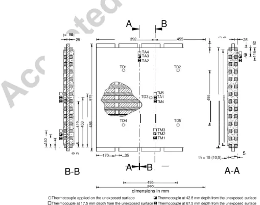
As it was stated above, the main goal is to study experimentally and numerically the behaviour
of tabique walls subjected to fire conditions using different earth-based render thicknesses. Hence,
wire type K thermocouples have been placed at different depths in order to obtain temperature
records inside the render (TA) and the wood (TM). The unexposed surface was also instrumented
using type K thermocouples welded on copper discs protected by plasterboard (TD) used for
measuring temperatures at specific panel points in order to assess and to verify the insulation
criterion. The thermocouples were placed according to Fig. 6.
95 25
975
419 453 486
150 1 1 6
8 2
B-B
A
B
392 455 TA4 TA3 TA2TD1 TD2
TD3 TM5 TA1 TM4
TD4 TD5
TM3 TM2 TM1 170 35
A
B
3 5 25 82 49 116 4 95 905865th = 15 (10;5) 5
A-A
495990
dimensions in mm
Thermocouple applied on the unexposed surface Thermocouple at 42.5 mm depth from the unexposed surface
Thermocouple at 17.5 mm depth from the unexposed surface Thermocouple at 67.5 mm depth from the unexposed surface
Fig. 6 Panels geometry and thermocouples location.
2.4
Tabique
panel coupled to the fire-resistance furnace
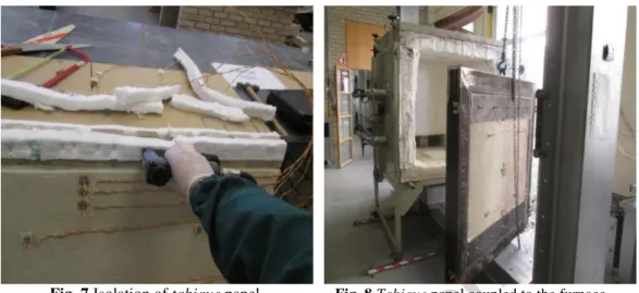
Before coupling the panel, a 50 mm thick rock wool was nailed along the perimeter of the panel in
order to avoid gas or flame escaping between the rim and the panel, Fig. 7. The tabique panels
were then fixed into a support and coupled to the furnace, Fig. 8.
Fig. 7 Isolation of tabique panel. Fig. 8 Tabique panel coupled to the furnace.
3 Experimental tests
The experimental tabique panels were tested in the fire resistance furnace existing in the Strength
of Materials Laboratory at Polytechnic Institute of Bragança, which is able to carry out ISO 834
standard fire tests, as defined in Fig. 9.
Furnace imposed temperature ISO 834
panel th = 15 mm panel th = 10 mm
T [ºC] panel th = 5 mm
1000
800
600
400
200
0
0 600 1200 1800 2400 3000 3600
t [s]
Fig. 9 ISO 834 and imposed temperature curves
At the beginning of the tests, the tabique wall panels were at the ambient laboratory
temperature of about 21°C and air humidity around 65%.
During the test, the integrity of the wall was evaluated throughout the cotton wool pads test
unexposed surface temperature according to European standard [10]. At the final stage of the tests,
a significant amount of smoke releasing from burning wood (Fig. 11) was noticed.
In order to evaluate the fire insulation behaviour of the earth-based render thickness effect, the
three panels were covered with different render layer thicknesses (th) equal to 15 mm, 10 mm and
5 mm.
Fig. 10 Integrity criterion proofing. Fig. 11 Smoke release.
3.1
Tabique
panel with th = 15 mm of earth-based render
The first tested sample was the wall panel with th = 15 mm of earth-based render. The lack of
knowledge on tabique fire behaviour and the smoke release from the burning timber, which could
indicate the ignition of the wood panel, led us to finish the test after 35 min. Fig. 12 shows the wall
panel when the furnace door was opened. It can be observed that the earth-based render did not
crack nor collapsed and that the laths burnt due to the small spaces created near the anchorage
points of the wall panel. The earth-based render of the fire exposed surface of the panel was
removed for a better perception of the fire effect on the laths, see Fig. 13. In general, it was noticed
that the timber did not suffer significant damage. However, a char layer was created around the
laths. In terms of the performance criterion, there was no deformation of the panel regarding
load-bearing capacity. On the other hand, the integrity criterion was also verified because there was no
flame or ignitions of the cotton. At the same time, the insulation criterion was as well verified
taking into account that the higher value of temperature measured in thermocouple TD3 was of
55°C.
Fig. 12 Tabique wall panel at the end of the test. Fig. 13 Timber structure after the test.
3.2
Tabique
panel with th = 10 mm of earth-based render
From the analysis of the results obtained in the previous test (th = 15 mm) it was decided to extend
the test duration from 35 min to 60 min in this case (tabique wall panel with th = 10 mm).
Nevertheless, both insulation and integrity criteria were met. The recorded temperatures of the
unexposed surface of the panel were always below 90°C. There was also no deformation of the
panel. Fig. 14 shows the timber structure burning during the test. Meanwhile, Fig. 15 shows the
panel in flame when the door of the furnace was opened.
Fig. 14 Flame from wood combustion. Fig. 15 Tabique wall panel when the door was
opened.
Afterwards, the flame was extinguished and the tabique wall panel was forced to cool using tap
water. At this stage, it was possible to observe the existence of cracks in the exposed surface of the
panel. A large vertical crack was formed at the centre of the tabique wall panel and also some
other small ones in horizontal direction (Fig. 16). The final aspect of the timber structure can be
observed in Fig. 17, which shows the complete carbonization of the horizontal (laths) and the
vertical timber elements of the tabique wall panel. Based on the scale of damage caused to the
tabique wall panel and the large amount of smoke release it was decided to shorten the duration of
the third test.
3.3
Tabique
panel with th = 5 mm of earth-based render
The third tabique wall panel (th = 5 mm) was tested during 15 min, which was the duration found
to be the one corresponding to the plateau of the graphs that can be observed from Fig. 28 to Fig.
32. When the furnace door was opened and the tabique wall panel was cooled (using water spray),
the fire exposed surface presented signs of spall. In fact, the earth-based render layer separated
rapidly from the wooden structure due to the thermal shock generated by the water particles in
contact with the hot surface. Fig. 18 shows the aspect of the tabique wall panel at the end of the
test and Fig. 19 shows the timber structure after removing the earth-based render layer. It is
possible to verify that the timber structure remained intact. In terms of the performance criterion, it
was also verified that there was no deformation of the panel. The integrity criterion was also met
because there was no flame or ignitions of the cotton. Finally, the insulation criterion was as well
met since the higher temperature value measured by thermocouple TD3 was 21°C.
Fig. 18 Tabique wall panel
afteropening the furnace door.
Fig. 19 Timber structure after the test (th = 5 mm).
4 Numerical analysis
A finite element analysis was performed using the Ansys software. A nonlinear thermal and
transient analysis was conducted using plane elements with 8 nodes (Plane 77). Two different
cross-sections of the tabique wall, AA and BB as shown in Fig. 3, were modelled in numerical
simulation. Particular attention was given to the non-linearity due to the thermal properties
dependence of wood and earth-based render material used in tabique walls [12].
The wood thermal properties have a nonlinear behaviour that depends on the evolution
temperature as defined in annex B of Eurocode 5 [13]. The thermal properties to be considered are
the thermal conductivity, the specific heat and the density, as shown in Fig. 20. It was considered a
density and an emissivity of the wood equal to 450 kg/m3 and 0.8, respectively.
The render properties were determined according to several documents that characterize the
thermal behaviour of the soil as it is stated in the Eurocode 6 [14] and in Nguyen [15]. The
considered thermal properties of the soil used in the tabique wall panels were established and
adjusted after several numerical simulations which were validated using the obtained experimental
results. Fig. 21 presents the thermal properties of the earth-based render considered in the
numerical analysis. The density and the emissivity of the render were considered equal to 1290
kg/m3 and 0.85, respectively.
Specific heat [kJ/kgK] Density ratio Thermal conductivity [W/mK]
12 14
12 10
10
8
8
6
6
4 4
2 2
0
0
0 200 400 600 800 1000 1200
Temperature [ºC]
Specific heat [kJ/kgK] Thermal conductivity [W/mK]
0 200 400 600 800 1000 1200
Temperature [ºC]
Fig. 20 Thermal properties of wood. Fig. 21 Thermal properties of earth-based
render.
The following figures (Fig. 22 to Fig. 27) show the mesh used in the numerical model with the
two different materials and also the obtained temperature patterns for each section (AA and BB,
see Fig. 3) in the last time step for tabique wall panels with th = 15 mm (Fig. 22 and Fig. 23), th =
10 mm (Fig. 24 and Fig. 25), and th = 5 mm (Fig. 26 and Fig. 27), respectively.
BB
AA
28.2°C 834.7°C
62.5°C 834.7°C
Fig. 22 Temperature results in section AA –
tabique wall panel with th = 15 mm, t = 35 min.
Fig. 23 Temperature results in section BB –
tabique wall panel with th = 15 mm, t = 35 min.
AA BB
74.85°C 926.39ºC 39.13°C 930.35°C
Fig. 24 Temperature results in section AA –
tabique wall panel with th = 10 mm, t = 60 min.
Fig. 25 Temperature results in section BB –
tabique wall panel with th = 10 mm, t = 60 min.
AA BB
30.93°C 711.81°C 17.42°C 712.44°C
Fig. 26 Temperature results in section AA –
tabique wall panel with th = 5 mm, t = 15 min.
Fig. 27 Temperature results in section BB –
The grey colour is related to the burned timber, according to the criterion of char layer
formation applied by the isothermal of 300 ºC, defined by Eurocode 5 [13].
5 Experimental and numerical results
The following graphs (from Fig. 28 to Fig. 33) show the experimental time-temperature evolution
of the fire exposed surface (T_e) and the corresponding numerical results (T_n) of the tabique wall
panels with 15 mm, 10 mm and 5 mm render thickness, respectively, and related to the
thermocouples located on the wooden structure (TM) and on the earth-based render (TA).
5.1
Tabique
panel with th = 15 mm of earth-based render
For the tabique panel with th = 15 mm, the test was performed over a period of time of 35 min
corresponding to a maximum real temperature in the furnace of 863ºC.
From Fig. 28, it can be seen that thermocouples TM1 and TM4 (which are placed in the wood
at 67.5 mm depth from the unexposed fire surface) recorded the highest temperatures of
approximately 100°C. Concerning the thermocouples located near the unexposed surface (17.5
mm deep), the temperature remained almost unchanged (ambient temperature). The covering layer
isolated the heat coming from the furnace for a period of 140 s approximately until it reached the
laths existing in the fire exposed face. At that moment, the temperatures recorded by
thermocouples TM1 and TM4 rose linearly until 97°C. At that temperature, the thermocouples
inserted in the vertical boards (TM2) and in the laths of the unexposed side (TM3 and TM5) began
to register an increase of temperature. The plateau occurred at the temperature of 97°C is due to
water evaporation. In this process, both materials accumulate energy in an endothermic process.
When the water evaporation ended, the temperatures measured by thermocouples TM1 and TM4
increased again, following the same evolution that in the first stage of the test. At the end of the
test (2100 s), temperatures of 29°C and 132ºC were registered in thermocouples TM3 and TM4,
respectively.
Although the maximum recorded temperature in the furnace was of 863ºC, it must be noticed
that the corresponding temperature recorded near the exposed surface was of 132ºC, which
represent a temperature reduction of 85%.
Temperature measurements were recorded through earth-based render thickness. Higher
temperature was recorded in thermocouples located near the fire exposed surface, as it was
expected.
Thermocouples located in the wooden structure (TM)
T [ºC] TM1_e TM2_e TM3_e TM4_e TM5_e
200 TM1_n TM2_n TM3_n TM4_n TM5_n
150
TM5 TM4
100
TM3
TM2
TM1
50
0
0 300 600 900 1200 1500 1800 2100
t [s]
Fig. 28 Time-temperature evolution of the wooden structure of the tabique wall panel with th =
15 mm.
Regarding the results obtained for the earth-based render (Fig. 29), the thermocouples placed
near the fire exposed side (TA1 and TA2) started to record an increasing temperature after
approximately 300 s until attain the moisture loss plateau, at 600 s. The duration of this plateau
was about 670 s while the temperature increased from 90°C to 100°C, followed by a temperature
increasing until the end of the test. The thermocouples inserted near to the unexposed surface
(TA3 and TA4) behaved similarly, measuring an initial temperature rise until the moisture loss
plateau, recording lower temperatures compared to TA1 and TA2, due to the render layers. The
highest recorded temperature was about 180°C which was measured near the fire exposed side. In
contrast, the lowest temperature (about 80°C) was registered in 17.5 mm depth in the render.
Thermocouples located in the earth-based render (TA)
T [ºC] TA1_e TA2_e TA3_e TA4_e
200 TA1_n TA2_n TA3_n TA4_n
TA4 TA3 TA2
150
TA1
100
50
0
0 300 600 900 1200 1500 1800 2100
t [s]
Fig. 29 Time-temperature evolution of the earth-based render of the tabique wall panel with th
5.2
Tabique
panel with th = 10 mm of earth-based render
For the tabique panel with th = 10 mm, the test was performed over a period of 60 min
corresponding to a maximum temperature in the furnace of 947°C.
From Fig. 30 it can be seen that the measurements of the thermocouples TM1 and TM4 which
were placed in the wood (at 67.5 mm depth from the unexposed fire surface), indicate that the
temperature started to rise at t = 200 s until the wood moisture evaporation plateau was reached.
This plateau was longer than the occurred in the previous test due to the fact that the render of the
exposed fire surface was rebuilt and it had less drying time in the laboratory. After the moisture
loss plateau the temperature curves followed a similar trend until the end of the test. The
thermocouples TM1 and TM4 recorded the highest temperatures of 240°C approximately.
For t = 2100 s the same temperature of 100ºC approximately was recorded in both tabique wall
panels with 15 mm and 10 mm of render thickness. Regarding the measurements of the
thermocouples located near the unexposed surface, 17.5 mm deep, the temperature remained
practically unchanged until t = 1200 s, increasing to around 100ºC at the end of test.
Although the maximum recorded temperature in the furnace was of 947ºC, it must be noticed
that the corresponding temperature recorded near the exposed surface was of 240ºC, which
represent a temperature reduction of 75%.
Thermocouples located in the wooden structure (TM)
T [ºC] TM1_e TM2_e TM3_e TM4_e TM5_e
300
TM1_n TM2_n TM3_n TM4_n TM5_n
250
200 TM5
TM4
150
TM3 TM2
100 TM1
50
0
0 600 1200 1800 2400 3000 3600
t [s]
Fig. 30 Time-temperature evolution of the wooden structure of the tabique wall panel with th =
10 mm.
Regarding the earth-based render (Fig. 31), the higher measured temperature of about 380°C
was recorded near to the fire exposed side for t = 3600 s. For t = 2100 s, it was measured the
temperature of 180ºC approximately which corresponds to a similar testing scenario as occurred in
the panel with 15 mm render thickness. The lowest temperature (about 100°C) was recorded at a
17.5 mm depth in the render.
Thermocouples located in the earth-based render (TA)
T [ºC] TA1_e TA2_e TA3_e TA4_e
400 TA1_n TA2_n TA3_n TA4_n
TA4
350 TA3 TA2
300
250 TA1
200
150
100
50
0
0 600 1200 1800 2400 3000 3600
t [s]
Fig. 31 Time-temperature evolution of the earth-based render of the tabique wall panel with th
=10 mm.
Comparing Fig. 29 and Fig. 31 it is noticed that there is a plateau around the temperature of
100°C. This is due to the moisture content of each panel. This phenomenon would be more
expected in the panel which had the higher render layer thickness. This fact did not happen
because the panel with th = 10 mm broke when it was placed in the test frame and it was required
to rebuild it. The test was performed 24 hours afterwards and the amount of water of the render
was superior to that existing in the panel with th = 15 mm.
5.3
Tabique
panel with th = 5 mm of earth-based render
For the tabique panel with th = 5 mm the test was performed over a period of 15 min
corresponding to a maximum temperature in the furnace of 737°C.
It can be seen in Fig. 32 that the thermocouples TM1 and TM4 recorded the highest
temperatures of 100°C approximately. At the end of the test, the moisture loss plateau was not
complete. Regarding the thermocouples located near the unexposed surface, 17.5 mm deep, the
temperature remained practically unchanged during the entire test duration.
Although the maximum recorded temperature in the furnace was of 737ºC, it must be noticed
that the corresponding temperature recorded near the exposed surface was of 100ºC, which
Thermocouples located in the wooden structure (TM)
T [ºC] TM1_e TM2_e TM3_e TM4_e TM5_e
100 TM1_n TM2_n TM3_n TM4_n TM5_n
75
TM5 TM4
50
TM3 TM2 TM1
25
0
0 100 200 300 400 500 600 700 800 900
t [s]
Fig. 32 Time-temperature evolution of the wooden structure of the tabique wall panel with th =
5 mm.
Concerning the earth-based render (Fig. 33), the higher measured temperature of about 80°C
were recorded near to the fire exposed side. Meanwhile, the lowest temperature (about 50°C) was
registered at 17.5 mm depth.
Thermocouples located in the earth-based render (TA)
T [ºC] TA1_e TA2_e TA3_e TA4_e
125 TA1_n TA2_n TA3_n TA4_n
TA4 TA3 TA2
100
75 TA1
50
25
0
0 100 200 300 400 500 600 700 800 900
t [s]
Fig. 33 Time-temperature evolution of the earth-based render of thetabiquewall panel with th =
5 mm.
In terms of the numerical simulation, the time-temperature evolution of both earth-based render
and timber is in accordance with the experimental results. The material moisture release
phenomenon estimated by the thermocouples TM1 and TM4 was simulated numerically with
accuracy. The discrepancies between experimental and numerical results may be due to different
causes such as the natural tabique wall panel performance, the existence of some internal cracking
that may affect the measurements, the possible thermocouples displacement, the material
heterogeneity, among other. In general, a good correlation between the numerical and the
experimental results was obtained, mainly at the final stage of the experiments.
5.4 Thermocouples applied in the unexposed surface
Fig. 34 shows the temperatures recorded by the thermocouples applied in the unexposed surface of
the tabique wall panels.
T [ºC]
TD1_e TD2_e TD3_e TD4_e TD5_e TD_nAA TD_nBB
100
A B
80
TD1 TD2
60
a) TD3
40 TD4 TD5
20
A B
0
0 300 600 900 1200 1500 1800 2100
t [s]
T [ºC]
TD1_e TD2_e TD3_e TD4_e TD5_e TD_nAA TD_nBB
100
A B
80
TD1 TD2
60
b) TD3
40 TD4 TD5
20
A B
0
0 600 1200 1800 2400 3000 3600
t [s]
T [ºC]
TD1_e TD2_e TD3_e TD4_e TD5_e TD_nAA TD_nBB
100
A B
80
TD1 TD2
60
c) TD3
40 TD4 TD5
20
A B
0
0 100 200 300 400 500 600 700 800 900
t [s]
From Fig. 34 it is noticed that the temperatures of the unexposed surface remained practically
unchanged at around 21ºC until t = 900 s. According to EN 1363-1 [10], the insulation criterion
was verified.
5.5 Global damage comparison
A comparison between numerical and experimental fire damage modelling is done in Fig. 35 and
for the last stage of the test.
Tabique panel with th = 15 mm Tabique panel with th = 10 mm Tabique panel with th = 5 mm
Fig. 35 Final results of material damages: numerical and experimental modelling.
It can be seen in Fig. 35 that the numerical simulation predicted that approximately half of the
laths existing in the surface subjected to fire action burned for tabique wall panel with th = 15 mm.
This fire scenario was confirmed experimentally proving that there is a good agreement between
the numerical modelling and the experimental test regarding the final result.
For the tabique wall panel with th = 10 mm, the numerical prediction corresponded to the
damage that actually occurred in the structure. As it can be seen in Fig. 35, the laths were
completely burned. The vertical boards were slight affected because they showed a reduced rate of
carbonization. There was also a good relation between numerical and experimental simulations
despite some small differences.
Regarding the tabique wall panel with th = 5 mm, the numerical simulation shows that
approximate 1/3 of the thickness of laths suffered burning. In fact, a partial carbonization of laths
occurred experimentally. The numerical model captured quite accurately again the experimental
behaviour.
6 Infrared (IR) thermography
In the following figures we can see the infrared (IR) thermography diagrams at different testing
stages. The IR thermography is very helpful in this study because it allows us verifying the effect
of isolating the timber with an earth-based render and also the non-uniform thermal behaviour
across the wall, for instance. The results of the IR thermography complement the above ones
because the surface temperatures of the entire unexposed surface of the panel can be assessed. In
contrast, thermocouples measure temperatures locally. This field measurement is of great
importance to define the position of thermocouples used to find maximum temperature events in
future tests.
6.1
Tabique
panel with th = 15 mm of earth-based render
Fig. 36 shows the temperature evolution for the tabique panel with 15 mm of earth-based render
thickness.
(t = 10 min) (t = 20 min)
(t = 30 min) (t = 35 min)
Fig. 36 Infrared thermography of the tabique wall panel with th = 15 mm.
The minimum temperature recorded throughout the test is 22.6°C. The average temperature at
the end of the test was 52°C. According to IR thermography, the temperature of the outer face of
the panel began to increase at 20 min approximately, and ranged to a maximum of 85°C. In this
panel, the highest experimental temperature of 55ºC was recorded by the TD3 thermocouple (refer
to Fig. 34).
6.2
Tabique
panel with th = 10 mm of earth-based render
Fig. 37 shows the evolution of the temperature of the outer face of the tabique wall panel with a
(t = 10 min) (t = 20 min)
(t = 30 min) (t = 40 min)
(t = 50 min) (t = 60 min)
Fig. 37 Infrared thermography of the tabique wall panel with th = 10 mm.
In this case, the minimum temperature recorded throughout the test is 58°C. The average
temperature at the end of the test was 76°C, as shown in Fig. 37. According to the IR
thermography, the increasing of temperature was noticed after 10 min and ranged to a maximum
of 90°C. For current test, the highest experimental temperature of 70ºC was recorded by the TD5
thermocouple (refer to Fig. 34). In this case there is a sharp increase of the temperature because the
panel has a lower render thickness.
6.3
Tabique
panel with th = 5 mm of earth-based render
Fig. 38 shows the temperature evolution of the tabique panel with 5 mm of earth-based render
thickness.
(t = 5 min) (t = 10 min)
(t = 12 min) (t = 15 min)
Fig. 38 Infrared thermography of the tabique wall panel with th = 5 mm.
In this case, the minimum temperature recorded throughout the test is 21°C. The average
temperature at the end of the test was 28°C. According to IR thermography, the increasing of
temperature of the outer face of the panel was noticed after 5 min and it reached the maximum
value of 35°C. At the same time, the highest experimental temperature of 26ºC was recorded by
TD1 thermocouple (see Fig. 34). The temperature evolution was more pronounced in this panel
because its render layer is thinner.
6.4 Comparison between
tabique
panels with different
earth-based render thicknesses
Fig. 39 presents the IR thermography diagrams obtained at t = 900 s for each tested panel. Fig. 40
shows the time-temperature evolution of the unexposed surface.
T [ºC] IR1 IR2 IR_3 IR_4 IR_5 100
IR 1 IR 2
80
IR 3
60
IR 4 IR 5
40
20
0
0 300 600 900 t [s] 1200 1500 1800 2100
15 mm thick render layer
T [ºC] IR1 IR2 IR3 IR4 IR5
100
IR 1 IR 2
80
IR 3
60
IR 4 IR 5
40
20
0
0 600 1200 1800 2400 3000 3600
t [s]
10 mm thick render layer
T [ºC] IR1 IR2 IR3 IR4 IR5
100
IR 1 IR 2
80
IR 3
60
IR 4 IR 5
40
20
0
0 100 200 300 400 t [s] 500 600 700 800 900
5 mm thick render layer
Fig. 40 Time-temperature evolution of the tabique wall panels by IR thermography
(unexposed surface).
From Fig. 36 to Fig. 39 the wood insulation effect is noticed as well as the insulation effect of
the different earth-based render thicknesses considered. At t = 3600 s, the surface temperature
increased up to 80ºC, which means that the insulation criterion was fully verified because the
average temperature increase did not exceed 140°C in relation to the initial average temperature.
Moreover, the maximum temperature at any point of the unexposed surface did not exceed the
final temperature of 180°C. Therefore, it can be concluded that the earth-based render acted as a
fire exposure protecting layer for the wooden structure improving the overall fire performance of
this type of building element.
Fig. 40 shows the time-temperature evolution of the points of the unexposed surface in where
the thermocouples were placed and using infrared thermography (see Fig. 3). Comparing the
respective time-temperature evolution obtained by these two data acquisition procedures it is
possible to figure out that there is adequate accordance.
7 Conclusions
This paper presents the first research study related to fire behaviour of tabique walls, concerning
its fire resistance. An experimental program including tabique panels manufactured in laboratory
was developed. The tabique panel represents a portion of a real-scale wall, and all the dimensions
are real ones, like the tabique panels that can be met in real buildings. Experimental results
allowed the authors to verify that both criteria (insulation and integrity) defined in the European
standard for fire resistance tests [10, 11] were fulfilled by the three tested tabique wall panels for
the whole test duration.
The insulation criterion verification was conducted according to the relation between the
average temperature increase and the average initial temperature, which was not higher than
140°C. Moreover, the maximum temperature at any point of the unexposed surface of the tabique
panel did not exceed the final temperature of 180°C, above the initial average.
The integrity criterion was observed throughout the experiments by employing a cotton wool
pads saturated in ethyl alcohol. No flame or ignitions of the cotton have been identified. However,
a significant amount of smoke release from burning wood was noticed at the final stage of the test.
The earth-based render acted as a fire protection layer to the wooden structure improving
significantly the fire resistance of this building construction element.
The tabique walls behaviour was similar in all experimental tests. It can be seen that the
highest temperatures were recorded near to the exposed surface, as it was expected. The
temperature evolution was more pronounced in tabique panel with thinner render layer.
Concerning the temperatures recorded at 1/5 depth from the unexposed surface, the temperature
remained almost unchanged at the ambient value.
The time-temperature evolution shows that the first part of the graphics remains unchanged
because a covering layer isolated the heat coming from the furnace during a period of 120 s at 200
s approximately until it reached the laths existing in the fire exposed face. At that moment, the
temperature near to the exposed surface rose linearly until the wood moisture evaporation plateau
was reached. Afterwards, the temperatures of the unexposed surface began to increase. In this
process, both materials accumulate energy in an endothermic process. When the water evaporation
ended, the measured temperatures increased again, following the same evolution slope than the
Temperature measurements were recorded through earth-based render thickness.
Comparing the three tabique wall panels for t = 900 s, the maximum imposed temperature in
the furnace was of 737ºC, while the corresponding temperature recorded near the exposed surface
was of 100ºC, which represent a temperature reduction of 85%.
The numerical temperatures show good agreement with the experimental results (temperature
and position of the char layer). The numerical models were validated experimentally, allowing
calibrating and adjusting the material properties used in the tabique wall panels.
The obtained results may be valuable because they allow improving the knowledge and
simulation on tabique walls behaviour subjected to fire conditions. In particular, they contribute to
predict the failure criteria due to fire, increasing the safety of people and property.
References
[1] ISO, ISO 834-1 - Fire-resistance tests - Elements of building construction – Part 1: general requirements, 1999.
[2] A. Cepeda, A. Murta, J. Lousada, J. Pinto, L. Fernandes, P. Tavares, P. Silva, H. Varum, Tabique construction in Alto Tâmega, Structures and Architecture (2010).
[3] J. Pinto, G. Gulay, J. Vieira, V. Meltem, H. Varum, I. Bal, A. Costa, Save the Tabique Construction, Structures and Architecture (2014).
[4]J. Pinto, H. Varum, D. Cruz, D. Sousa, P. Morais, P. Tavares, J. Lousada, P. Silva, J. Vieira, Tabique Construction Characterization in Douro North Valley, Portugal: A First Step to Preserve this Architectural Heritage, 2nd WSEAS International Conference on Urban Rehabilitation and
Sustainability (URES’09). Environmental Science and Sustainability, WSEAS Press, Baltimore,
USA, 2009, pp. 48-53.
[5] J. Pinto, H. Varum, A. Cepeda, P. Tavares, J. Lousada, P. Silva, J. Vieira, Study Of The Traditional Tabique Constructions In The Alto Tâmega Region, Wessex Institute of Technology, UK, 2010, pp. 299-307.
[6]S. Cunha, J. Pinto, A. Paiva, A. Briga-Sá, N. Soares, H. Varum, D. Ferreira, A contribution for the improvement in thermal insulation of tabique walls coated with metal corrugated sheets, Journal of Building Services Engineering Research & Technology 36(4) (2015) 439-454.
[7] P. Kuklík, M. Charvátová, The behavior of OSB board´s fire protection coating under the nominal fire, M2D 2015 - 6th International Conference on Mechanics and Materials in Design, P. Delgada/Azores, Portugal, 2015, pp. 2409-2414.
[8] M. Drdácký, M. Kloiber, Considerate SDT methods for safety assessment of historic timber, M2D 2015 - 6th International Conference on Mechanics and Materials in Design, P. Delgada/Azores, Portugal, 2015, pp. 2349-2350.
[9]A. Araújo, E. Fonseca, D. Ferreira, P. Piloto, J. Pinto, Fire behaviour of tabique walls, IFireSS - International Fire Safety Symposium, Coimbra, Portugal, 2015, pp. 109-110.
[10] CEN, EN 1363-1 - Fire resistance tests - Part 1: General requirements, Central Secretariat, Brussels, 1999.
[11]CEN, EN 1364-1 - Fire resistance tests for non-loadbearing elements - Part 1: Walls, Central Secretariat, Brussels, 2015.
[12] D. Ferreira, A. Araújo, E. Fonseca, P. Piloto, Fire behaviour of tabique wall - experimental and numerical study, M2D 2015 - 6th International Conference on Mechanics and Materials in Design, P. Delgada/Azores, Portugal, 2015, pp. 2331-2340.
[13]CEN, EN 1995-1-2 - Eurocode 5: Design of timber structures - Part 1-2: General – Structural fire design, Central Secretariat, Brussels, 2004.
[14] CEN, EN 1996-1-2 - Eurocode 6: Design of masonry structures - Part 1-2: General rules – Structural fire design, Central Secretariat, Brussels, 2005.
Highlights
First research related to fire behaviour of tabique wall.
The insulation criterion was verified on tabique wall exposed to fire.
The integrity criterion was verified as no flame or ignitions have been identified.
The earth-based render significantly improved the fire resistance.
The numerical model show good agreement with the experimental results.