Experimental Behaviour and Numerical Analysis of
dampers
MR Dampers
M. T. Braz-César
Polytechnic Institute of Bragança, Portugal
R. C. Barros
University of Porto, Portugal
SUMMARY:
This paper presents the results of an experimental and numerical analysis developed to study the non-linear hysteretic behavior of MR dampers. In the first section a brief review of the numerical models available to simulate their behavior will be presented. To obtain and analyze the hysteretic behavior of MR dampers, a device was experimentally tested under several input excitations. Based on the experimental results an identification procedure was carried out to determine the parameters that are necessary to develop a numerical model. Finally, results from experimental investigations and numerical analyses are summarized and compared.
Keywords: MR dampers, hysteretic response, parametric models.
1. INTRODUCTION
MR dampers are semi-active devices that can achieve high-level controllable forces and better performance than passive systems although preserving the performance reliability of passive devices and with low energy requirements. However, the highly nonlinear behavior of a MR Damper related with its semi-active nature increases the level of complexity of the behavior numerical modeling, especially when parametric models are used.
In the present paper is presented the experimental testing and numerical modeling of the RD-1005-3 MR damper manufactured by Lord Corporation. To predict the behavior of the MR damper, it is necessary to use a numerical procedure capable to capture its non-linear hysteretic response. However, some experimental data are needed to calibrate and validate the numerical response for a specific MR damper. The usual approach to determine the MR damper behavior involves measuring the MR damper response at a constant operating current level (or voltage) under a sinusoidal displacement of the damper piston. Hence, an experimental study was carried out under different current magnitudes, frequencies and amplitudes of excitation in order to characterize the MR damper response. The experimental data will be presented and analyzed and will be used to identify the model parameters that are required to develop some parametric models for this device. These models must predict the experimental nonlinear hysteretic response of the MR damper in the whole operating range to allow developing an accurate numerical model.
2. NUMERICAL MODELS
Among the modeling techniques, parametric models appear to be an easy and reliable approach to obtain a mathematical model of the physical MR damper. Several numerical models are available to predict the response of MR dampers. Table 2.1 presents a brief description of the available models for MR dampers. Among these, the Bingham model, the Bouc-Wen and the Modified Bouc-Wen models are some of the most common models utilized to predict the MR damper behavior.
Table 2.1. MR dampers Models classification
Modelling technique MR damper Models
Bingham models
- Original Bingham model - Modified Bingham model - Gamota and Filisko model
- Updated Bingham model by Occhiuzzi et al. - Three-element model by Powell
Bi-viscous models
- Nonlinear bi-viscous model
- Nonlinear hysteretic bi-viscous model - Nonlinear hysteretic arctangent model - Lumped parameter bi-viscous model
Visco-elastic-plastic models - General visco-elastic-plastic models - Visco-elastic-plastic model by Li et al Stiffness-viscosity-elasto-slide model - Stiffness-viscosity-elasto-slide (SVES) model
Hydro-mechanical model - Hydro-mechanical model
Maxwell models - BingMax model by Makris et al. - Maxwell Nonlinear Slider model
Bouc-Wen models
- Simple Bouc-Wen model - Modified Bouc-Wen model
- Bouc-Wen model for shear mode dampers - Bouc-Wen model for large-scale dampers - Current dependent Bouc-Wen model
- Current-frequency-amplitude dependent Bouc-Wen - Non-symmetrical Bouc-Wen model
Dahl models - Modified Dahl model
- Viscous Dahl model
LuGre models - Modified LuGre model by Jimenez and Alvarez - Modified LuGre model by Sakai et al
Hyperbolic tangent models - Hyperbolic tangent model by Kwok et al Sigmoid models - Sigmoid model by Wang et al and Ma et al Equivalent models - Equivalent model by Oh and Onoda
Phase transition models - Phase transition model
2.1. Bingham model
Stanway et al (1987) proposed a mechanical model based on the Bingham plastic model to characterize the ER damping mechanism. This model is known as the Bingham model and combines a Coulomb friction element in parallel with a viscous dashpot as shown in Fig. 2.1.
Figure 2.1. Bingham model for MR dampers c0 fc x F – fi fi ˙ ˙ ˙ fi fi fl fl fl fi ˙ ˙ − ˙ ˙ − ˙ ˙ ˙ fl ˙ fl fl fl fi fi fluid fl fl fi flu fl ˙
π [ ˙ − ˙ ¨
Form the equilibrium of the mechanical element configuration the force generated by the MR dampers can be expressed as
( ) ̇ ( ̇) (2.1)
where ̇ is the velocity of the external excitation, c0 is the damping coefficient, fc is the frictional force
and f0 is the force offset related with the presence of an accumulator.
2.2. Bouc-Wen model
The simple Bouc-Wen model has three components: a spring, a dashpot and a Bouc-Wen block, in a parallel configuration as shown in Fig. 2.2.
Figure 2.2. Simple Bouc-Wen model for MR dampers
According to the mechanical configuration shown in Fig. 2.2, the damping force is given by
( ) ̇ ( ) (2.2)
where c0 is the viscous coefficient, k0 the stiffness coefficient and z is an evolutionary variable
associated with the Bouc-Wen block and governed by
̇ | ̇| | | ̇| | ̇ (2.3)
The parameters c0, k0, α, β, γ, n and A are usually called characteristic or shape parameters of the Bouc–Wen model and are functions of the current, amplitude and frequency of excitation.
2.3. Modified Bouc-Wen model
The modified Bouc-Wen model combines a simple Bouc-Wen block with two new mechanical components (a spring and a dashpot) as shown in Fig. 2.3.
Figure 2.3. Modified Bouc-Wen model for MR dampers
Bouc-Wen x F c0 k0 Bouc–W fi
α β γ –
–W
fi
–W
ntifi
α γ β
Modifie –W
fig
˙ −
˙ α ˙ −
fi
˙ −γ| ˙ − ˙ − −β ˙ − ˙ ˙ − ˙
ifi –
γ β
odifi –W
)–(
tifi
α γ β
fie
α α α α
α fi
fi fi
˙ −η −
η fl η
–W )–(
ntifi
α α γ β η
Bouc–W
fi
α β γ –
–W
fi
–W
ntifi
α γ β
Modifie –W
fig
˙ −
˙ α ˙ −
fi
˙ −γ| ˙ − ˙ − − β ˙ − ˙ ˙ − ˙
k k c F x y Bouc-Wen 0 0 c1 1 ifi – γ β odifi –W )–( tifi
α γ β
fie
α α α α
α fi
fi fi
˙ −η −
η fl η
–W )–(
ntifi
In this parametric model, the MR damper force can be obtained by the following equations:
( ) ( ̇ ̇) ( ) ( ) ̇ ( ) (2.4)
where z is the evolutionary variable given by
̇ | ̇ ̇| | | ( ̇ ̇)| | ( ̇ ̇) (2.5)
and y is the internal displacement of the MR damper given by
̇ ( ) ̇ ( ) (2.6)
In these equations, c0 represent the viscous damping at large velocities, c1 the viscous damping to
produce the roll-off effect observed at low velocities, k0 regulate the stiffness at large velocities, k1 is
related with the accumulator stiffness and x0 is used to account for the effect of the accumulator. As in
the simple Bouc-Wen model, the non-linear shape of the hysteretic curve can be adjusted by changing the values of the Bouc-Wen block parameters A, β, γ and n. Usually, these parameters are considered fixed while the parameters α, c0, c1 are assumed to be functions of the applied current.
3. EXPERIMENTAL PROGRAM
The RD-1005-3 MR damper has a conventional cylindrical body configuration filled with 50 ml of MR fluid and comprising the piston, the magnetic circuit with a coil resistance of 5 Ω and the accumulator. The enclosing cylinder is 41.4 mm in diameter and the damper is 208 mm long in its extended position with ±2.5 cm stroke. The device can operate within a current range from 0.0 A up to 2.0 A with a recommended input value of 1.0 A for continuous operation and can deliver a peak force of 2224 N at a velocity of 51 mm/s with a continuous operating current level of 1.0 A. The MR damper can reach at least 90% of maximum level during a 0.0 amp to 1.0 amp step input in less than 25 milliseconds.
A series of sinusoidal displacement excitation tests were performed to measure the response under different loading conditions in order to obtain the MR damper hysteretic response. The device was mounted into the MTS hydraulic actuation system and was then excited with a sinusoidal displacement. Several arrangements of amplitudes, frequencies and input current/voltage were studied in order to obtain the required experimental data to conveniently characterize the damper response. A thermocouple was connected with to the MR damper enclosure to verify if the operating temperatures developed during the tests are within the device range to avoid overheating.
The sinusoidal excitation was directly produced using the MTS controller device and the measured response data, i.e., the load cell signals (force) and the hydraulic actuator displacement, were collected and recorded with the MTS software in a data acquisition system connected to the controller. These data were later processed with MATLAB package to obtain the response plots and also to obtain the model parameters through an identification procedure.
Table 3.1 sinusoidal excitation parameters RD-1005-3 MR damper
Parameter Values
Frequencies (Hz) (0.50, 1.00, 1.50, 2.00)
Amplitudes (mm) (2.0, 4.0, 6.0, 8.0, 10.0)
Current supplies (A) (0.00, 0.10, 0.20, 0.25, 0.50, 0.75, 1.00)
The testing procedure was carried out with a fixed frequency and amplitude sinusoidal displacement for a specific current supply repeating this process for every parameter combination (Table 3.1). The experimental data of the parametric study for MR dampers are typically grouped according to the variability of the different parameters sets as current input tests, frequency-dependent tests and amplitude-dependent tests.
Figure 3.1. Experimental results (1Hz, 4mm and variable current input)
Fig. 3.1 shows the result for the current input tests. As expected, the damping force increase along with the operating current level and the typical rheological behavior of the MR damper is observed. When the device is operating without an operating current, the damper response exhibits a reduced hysteretic behavior with a narrow hysteretic loop while operating with a non-zero constant input current level the damper exhibit a significantly larger hysteretic behavior.
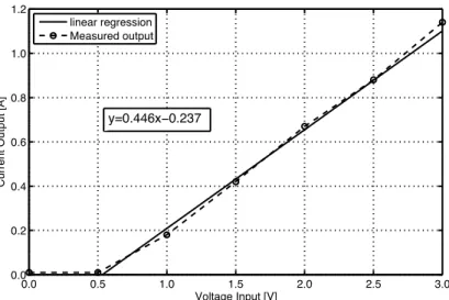
Figure 3.2 Voltage-to-current converter relationship (RD-1005-3)
The response time was also studied. According with the device specifications, the MR damper can reach at least 90% of maximum level in response to a step input (0.0 A to 1.0 A) in less than 25 milliseconds at a constant piston velocity of 2 in/sec (51 mm/sec). A parametric study was carried out for four input voltages (1.0, 1.5, 2.0 and 2.5 V).
The procedure used to compute the response time from the experimental data is shown in figure 3.3. The initial and final values of the measured response times for the step input with 2.0 V were found to be 17 ms (95% limit) and 43 ms (5% limit) respectively. Therefore, the activation of the MR fluid (OFF-ON) is significantly faster than the deactivation (ON-OFF) process due to the residual magnetization effect.
Figure 3.3. Response time for a square wave voltage of 2.0 V
The response time can be considered as a first-order time lag in the device response. Hence, the rise time can be included using a first-order filter given by
̇ ( ) (3.1)
where νinput is the desired command signal input applied to the converter, uinput is the real signal output and η=1/T is a time constant parameter. In this case, the measured output signal can be approximated by the time constant η=130 sec-1
.
0.10 0.15 0.20 0.25 0.30 0.35 0.40 0.45 0.50 0.55 0.60 0.65 0.70
0.00 0.25 0.50 0.75 1.00 1.25 1.50 1.75 2.00 2.25 2.50
M
e
as
ured
v
ol
tag
e
[V
]
Time [s]
95%
5%
4. NUMERICAL SIMULATION
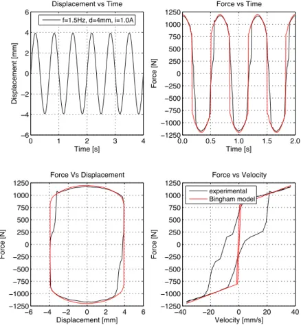
4.1. Bingham Model
The Bingham model involves the identification of three parameters (fc, c0 and f0). The force due to the accumulator can be determined directly from the experimental response since the accumulator produces a nearly constant force offset (f0 =40N) that can be measured by centering the experimental response plot. The parameters fc and c0 are voltage/current dependent and their values were computed with the parameter identification procedure previously described.
( ) (4.1)
( ) (4.2)
Fig. 4.1 show the experimental vs numerical response (f=1.5Hz, A= 4mm and I= 1.00A).
Figure 4.1. Experimental vs. numerical response Bingham model (1.50 Hz, 4mm and 1.00A)
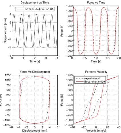
4.2. Bouc-Wen Model
The force offset f0 =40N has the same value of the Bingham model force offset and was assumed that n=2. It was observed that parameters A, β, γ show slow change with frequency, amplitude and input current.Then, the average values of the current independent parameters are A=30.852, β=0.081 mm-2, γ=1.507 mm-2 and k0 =1.984 N/mm. The current dependent parameters are given by
( ) (4.3)
Figure 4.2. Experimental vs. numerical response Bouc-Wen model (1.50 Hz, 4mm and 1.00A)
Fig. 4.2 shows the results for the Bouc-Wen model when the damper is driven with a harmonic excitation of 1.50 Hz with 4mm amplitude and an operating current of 0.75A. The results show that the simple Bouc-Wen model is capable to characterize the MR damper hysteretic response. However, the predicted computational results are still far from a perfect representation of the hysteretic behavior.
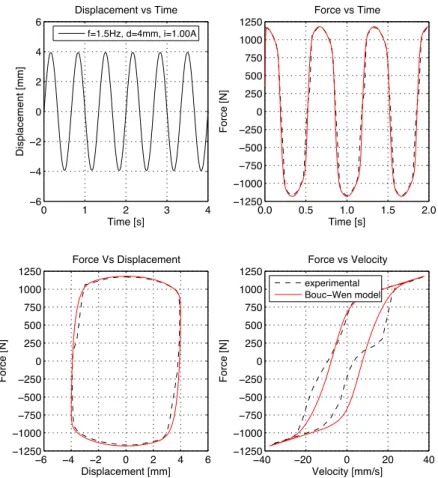
4.3. Modified Bouc-Wen model
The Modified Bouc-Wen model or Spencer model is a variation of the simple Bouc-Wen model to improve the nonlinear force-velocity hysteretic response of MR dampers since the simple Bouc-Wen model does not reflect the roll-off effect in the region where the acceleration and velocity have opposite signs and the magnitude of the velocities are small.
It was assumed that n=2 and the force offset, defined by k1(x-x0) that represent the force due to the accumulator existence, has the same value of the Bingham and the simple Bouc-Wen model force offset (f0 =40 N). The average values of the current independent parameters A=10.013, β=3.044 mm-2, γ=0.103 mm-2 and k0 =1.121 N/mm were found. The parameters α, c0 and c1 are described as functions of the input current by
( ) (4.5)
( ) (4.6)
( ) (4.7)
Figure 4.3. Experimental vs. numerical response Modified Bouc-Wen model (1.50 Hz, 4mm and 1.00A)
Fig. 4.3 show the numerical response obtained with the modified Bouc-Wen model. Comparing the three models is clear that the Bingham model can be used in very simple simulations of the damper response; although this model can reproduce the overall response, it is unable to process the typical non-linear hysteretic behavior of these dampers. The simple Bouc-Wen model is a more detailed model with the ability to simulate the non-linear hysteretic response; but the resulting hysteretic loops are incapable to reproduce the roll-off effect observed at low velocities. To overcome this problem, the enhanced Modified Bouc-Wen was developed and the roll-off effect was introduced in the numerical simulation. The drawback of the more elaborated modes is related with the number of parameters that are involved in the identification procedure, which increases the required computational work.
5. CONCLUSIONS
The present article addressed the non-linear hysteretic properties of MR dampers, presenting a general review of the available parametric modelling approaches. In the first section the parametric models were presented and three of the most common approaches were extensively reviewed. An experimental testing procedure was carried out to characterize the response of a commercial MR damper and the experimental data were used to develop several numerical models. These models require the definition of some model parameters that must be initially found to construct a realistic numerical response. Thus, an identification routine was developed and the predicted response was compared with the experimental data. As expected, more complex models are computationally cumbersome but are significantly more accurate than simpler models.
ACKNOWLEDGEMENT
REFERENCES
Carlson J.D. and Spencer Jr., B.F. (1996). Magneto-rheological fluid dampers: scalability and design issues for application to dynamic hazard mitigation. Proc. 2nd Workshop on Structural Control: Next Generation of Intelligent Structures. 99–109.
Cesar, M.B., . Barros R.C. (2010). Semi-Active Control of a Metallic Scaled Frame with a MR Damper: Numerical and Experimental Research. School and Symposium on Smart Structural System Technologies (S3T-2010). 419-440.
Dyke, S.J., Spencer Jr., B.F. (1997). A Comparison of Semi-Active Control Strategies for the MR Damper. Proceedings of the IASTED International Conference, Intelligent Information Systems.
Gattulli, V., Lepidi, M., Potenza, F.(2010). Mitigation of Seismic Vibration by Semi-Active Control. School and Symposium on Smart Structural System Technologies (S3T-2010). 347-367.
Guerreiro, L., Barros, R.C., Bairrão, R. (2007). Algorithms for Semi-Active Devices Control. Proceedings of ECCOMAS Thematic Conference “Computational Methods in Structural Dynamics and Earthquake
Engineering” (COMPDYN 2007). 262-268.
Guerreiro, L., Oliveira, C., Bairrão, R., Barros, R.C. (2010). Control Algorithms Development for Adaptative Protection Systems – Application to Bridges. School and Symposium on Smart Structural System Technologies (S3T-2010). 401-418.
Guglielmino, E., Sireteanu, T., Stammers, C.W., Ghita, G., Giuclea, M. (2008). Semi-active suspension control: improved vehicle ride and road friendliness. Springer.
Ikhouane, F., Rodellar, J. (2007). Systems with hysteresis: Analysis, identification and control using the Bouc-Wen model. John Wiley & Sons.
Li ,W.H., Yao, G.Z., Chen, G., Yeo, S.H., Yap, F.F. (2000). Testing and steady state modeling of a linear MR damper under sinusoidal loading. Smart Materials and Structures, 9, 95-102.
Oliveira, C.F., Bairrão, R., Barros, R.C., Guerreiro, L. (2008). The New Generation of Seismic Semi-Active and Active Protection Systems. Proceedings of the 4th European Conference on Structural Control, 8-12. api s i, , ilu , J. (2003). Analysis of parametric models of MR linear damper. Journal of Theoretical and
Applied Mechanics, 41:2, 215-240.
Spencer Jr., B.F., Dyke, S.J., Sain, M.K., Carlson, J.D. (1997). Phenomenological model of a magnetorheological damper. Journal of Engineering Mechanics, 123, 230-238.
Wang, D.H., Liao, W.H., (2011). Magnetorheological fluid dampers: a review of parametric modelling. Smart Materials and Structures, 20, 023001.