International Conference on Renewable Energies and Power Quality (ICREPQ’16) Madrid (Spain), 4th to 6th May, 2016
Renewable Energy and Power Quality Journal
(RE&PQJ) ISSN 2172-038 X, No.14 May 2016Development of a System for the Usability of Forest Residues for Electric Energy
Production
S. Baranovschi
1, A. Roque
1,2, D. Sousa
2,3and V. Fernão Pires
1,2 1Department of Electrical EngineeringESTSetúbal/Instituto Politécnico de Setúbal Campus of IPS, Estefanilha, 2914-761 Setúbal, Portugal
Phone/Fax number:+351 265790000; [email protected], [email protected], [email protected]
2INESC-ID
Av. Alves Redol 9, 1000-029 Lisboa, Portugal Tel. +351 213100300; Fax +351 213100235 Lisboa, Portugal
3DEEC AC-Energia, Instituto Superior Técnico, Universidade de Lisboa
Av. Rovisco Pais, 1 – 1049-001 Lisboa, Portugal, Tel.: +351 218417429, Fax: +351 218417167, [email protected]
Abstract.
Forest residue mass from timber harvests is a renewable resource that can be used for electrical utility production. Under this context, this work presents the development of a system for harnessing forest residues. The system consists in several different parts, constituting a complex mechanical-hydraulic-electrical coupling system. With the development of this system, forest residues and derivatives can be used through thermoelectric plants to produce electric energy. In this paper, the proposed system, due to its specific structure, supports a wider range of forest residues that can be processed, i.e., mixed residues of different sizes and shapes can be used simultaneously. In addition, this solution may allow to skip pre-processing fragmentation.Key words
Biomass; Forest residues; Electric Energy; Renewable resource.
1. Introduction
An important part of the electric supply is derived from coal fire plants. However, these power plants pollute the environment with toxins and contribute to the greenhouse effect, contributing to the rise of the global temperatures [1]. However, instead of using coal for the production of electrical energy, other products like biomass could be used. In fact, the use of biomass for the production of electrical energy is considered a renewable resource harvested from a several types of sources, such as brush, willow matter, crops, waste, timber, and forest residues [2,3]. The use of wood is a promising feedstock since it can be obtained from multiple sources. On other hand, wood biomass is less expensive when compared with fossil fuels, being the amount of carbon dioxide emitted during the burning process typically 90 % less and, in addition, wood contains
minimal amounts of sulfur and heavy metals. Due to this, forest detritus has been proposed to be used for the electrical energy production [4-7].
The residues for biomass plants are characterized by their dimension, moisture content and proportion of silica. Usually, the final product of the residues to be used in biomass power plants is generally accomplished through fragmentation processes. The residues are crushed and smashed between the rotating and fixed parts of a cutting machine, remaining in a closed cycle until a suitable size of the fragments are achieved. The systems used in the processes of fragmentation can be driven by internal combustion engines or by electric motors. Systems that use internal combustion engines are less efficient, however they can be installed in deforestation fields, for primary treatment of the trees branches, bushes and roots. Primary treatment involves the partial fragmentation of material in order to facilitate the accommodation of the same in heavy container vehicles. Regarding the machines that operate with electric motors, their use will be difficult in deforestation zones due to the lack of a power supply. In industrial environment the machines driven by electric motors are more advantageous due to its high efficiency and clean operation since they do not emit greenhouse gases into the atmosphere.
Under this context, this paper presents the development of a chipping machine for forestry residues which are pre-fragmented. The development of this machine will undergo several phases that determine its technical characteristics. The development of this machine is based on the following factors: amount of fragmented material in output discharge, operating safety, equipment life and ease of maintenance. It is necessary to emphasize the first
factor since it will be decisive for the size of the machine and hence their power consumption.
2. Proposed System
The proposed system consists essentially in three very distinct parts: the mechanical, the hydraulic and the electric. A - Machanical Part
The mechanical part is responsible by the fragmentation of forest or industrial residues. This fragmentation is achieved by the inertia of a rotating cylinder in order to cause fragmentation of residues. In fact, this fragmentation is due to the cutting blades mounted on the cylinder and fixed blades as shown in Fig. 1.
Fig. 1. View of the cutting chamber and of the cutting cylinder.
The residues that entering into the cutting chamber are pushed by blades placed on the rotating cylinder to the counter blades where they are crushed. The distance between the two cutting elements (blades and counter-blades) should be between 0.3 mm to 0.4 mm. Fig. 2 shows the cutter cylinder, being visible the location of the cutting blades. The characteristics of the cutting cylinder are shown in Table I.
Table I: Main characteristics of the cylinder and pulley
Cylinder Pulley
Diameter (m) 0.8 1.7 Weight (kg) 7911 1260 Volume (m3) 1 0,16 Surface (m2) 20.5 6,2 Moment of inertia (kgm2) 729 289Fig. 2. Cutting Cylinder.
Fig. 3 shows a view of the cutter cylinder where it is visible the brackets for the blades, the support of the opposite blades and sieve. The sieve separates the cutting chamber from the discharge chamber and is intended to set the maximum size for the crushed material.
Fig. 3. View of the cylinder incorporated in the system: (a) Support of the blades (b) support of the opposite blades (c)
sieve.
B - Hydraulic Part
The hydraulic system is designed to drive four hydraulic jacks, two in the front door and two in the rear door. The hydraulic jacks are solely used during the maintenance to the interior of the machine.
a) Rear door
b) Front door Fig. 4. Hydraulic Jacks.
The hydraulic system has a safety valve which is activated when the system pressure reaches 150 bar. There are flux controllers that in case of overloading during the expansion block the flux in the opposite direction. In the case of any failure of electrical nature there is the neutral position in the valves that control the direction of the flux, in order to immediately lock the oil in both directions. This eliminates the possibility of the doors fall in case of blackout.
The technical data of the hydraulic system are:
Maximum operating pressure: 150 bar
Displacement: 82 cm3/rev
rpm: 1200 (hydraulic pump motor)
C - Electrical Part
The operation of the proposed solution depends mainly on of the electrical part. The electrical part of the system comprises four electric motors M1, M2, M3 and M4 that are described below.
The residues are placed inside of the cutting chamber by a conveyor belt in driven by electric motor (M2) and the help of the feed cylinder driven by the motor (M4). The residues are fragmented by the cutting cylinder, which is driven by electric motor (M1). After the fragmentation, the residues are driven out of the machine by a conveyor belt out through the motor (M3).
In Fig. 5 is shown the electric motor M1 and the transmission system of the motor to the load (cutting cylinder). The transition system comprises two pulleys, one with a smaller size that is placed on the motor shaft, and the other one with larger size that is placed on the load shaft. Motor M1 provides mechanical energy to the cylinder that fragments the biomass (forestry or industrial) to later be used in biomass power plants for the production of the electricity.
Fig. 5. View of the M1 motor and transmission system.
The main characteristics of the cutting cylinder and pulley are presented in Table I.
Fig. 6. illustrates the transportation system of the residues for the cutting cylinder, where is visible the cutting cylinder, the feed cylinder, the feed chamber, the conveyor belt and the motor M2. The feed conveyor belt is intended to put the biomass in the cutting chamber. Motor M2 is designed to drive the conveyor belt that carries the biomass from the feed chamber to the cutting chamber.
Fig. 6. System for the transportation of the residues for the cutting cylinder.
In Fig. 7 is represented the view of the transportation system where is visible the feed cylinder and motors M3 and M4. The electric motor M3 is intended to drive the conveyor belt that carries the already fragmented biomass. The motor M4 is intended to drive the feed cylinder.
Fig. 7. Transportation system of the residues after passing the cutting cylinder.
3. Sizing of the Electric Motors
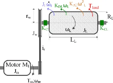
As described, this system requires several electric motors. For the sizing of the motors is necessary to take into consideration the load torque, Tload (Fig. 8), [8].
Fig. 8. Equilibrium of binaries in a system with elastic coupling.
The load torque of the motor is given by:
𝑇𝑚= 𝐽𝑡𝑑𝜔𝑑𝑡𝑚+ 𝑇𝑟+ 𝑇𝑙𝑜𝑎𝑑 (1)
where:
𝑇𝑟 - Resistant torque associated to the frictions: static,
viscous and turbulent 𝑇𝑙𝑜𝑎𝑑 - Load torque
The total inertia momentum can be calculated as follows: 𝐽𝑡= 𝐽𝑚+ 𝐽𝐿+𝑤´ (2)
where:
𝐽𝑡 - Total inertia momentum seen from the motor shaft
𝐽𝑚 - Inertia momentum of the motor
𝐽𝐿+𝑤´ - Inertia momentum of the load (cylinder) seen
from the motor shaft and Inertia momentum of the pulley (reduction gear) seen from the motor shaft For a homogeneous cylinder with specific mass μ the inertia moment can be given by:
𝐽𝐿= ∫ ∫ ∫ 𝑟0𝐿𝐿 0𝑅𝐿 02𝜋 𝐿2𝜇𝑟𝐿𝑑𝜃𝑑𝑟𝐿𝑑𝑙𝐿=12𝜋𝐿𝐿𝑅𝐿4𝜇 (3)
Where the cylinder mass is:
𝑀𝐿= 𝜇𝜋𝑅𝐿2𝐿𝐿 (4)
Taking into account the mass of the cylinder the inertia moment is given by:
𝐽𝐿=12𝑅𝐿2𝑀𝐿 (5)
The gear ratio of the reduction gear box can be given by the following expression:
𝑖𝑟=𝜔𝜔𝑚
𝐿 (6)
The inertia moment of the load (cylinder) seen from the motor shaft is given by:
𝐽𝐿´ =𝜂1 𝑟
1
𝑖𝑟2𝐽𝐿 (7)
where 𝜂𝑟 is the efficiency of the reduction gear box.
Regarding the biggest pulley that is integrated in the reduction gearbox, the inertia moment can be calculated by: 𝐽𝑤=12𝑟𝑤2𝑀𝑤 (8)
Making the reduction of this moment of inertia to the motor shaft, the new following expression is obtained:
𝐽𝑤´ =12𝑟𝑤 2
𝑖𝑟2𝑀𝑤 (9)
The resistive torque is inherent in each type of load and can have various origins. The resistant binaries considered are the following:
Resistant torque due to static friction or Coulomb
This torque is associated with dry friction, causing higher resistant torque in the transition from rest to motion. This torque can be given by:
𝑇𝑟= {+𝐾−𝐾𝐶 𝑓𝑜𝑟 𝜔 > 0
𝐶 𝑓𝑜𝑟 𝜔 < 0 (10) Resistant torque due to viscous friction
This torque is proportional to the velocity and is given by:
𝑇𝑟= 𝐾𝐷𝐿𝜔𝐿 (11)
Resistive torque associated with the turbulent flow of the fluids
This torque is described approximately by a quadratic function given by:
𝑇𝑟= 𝐾𝐴𝐿𝜔𝐿2 (12)
The gear ratio is given by the inverse of the torque, affected by the efficiency of the gearbox, 𝜂𝑟. According to
this the following relationship is obtained: 𝑖𝑟=𝜂1
𝑟
(𝑇𝐿+𝑤+𝑇𝑙𝑜𝑎𝑑)
𝑇𝑚 (13)
The torque seen from the motor shaft can be determined by:
𝑇𝑚=𝜂1 𝑟[
𝐽𝐿+𝑤𝜔̇𝐿+𝐾𝐷𝐿+𝑤𝜔𝐿+𝐾𝐴𝐿+𝑤𝜔𝐿2+𝐾𝐶𝐿+𝑤
𝑖𝑟 + 𝑇𝑙𝑜𝑎𝑑] (14)
The torque seen from the motor shaft as function of the motor speed is given by:
𝑇𝑚= 𝐽𝐿+𝑤´ 𝜔̇𝑚+ 𝐾𝐷𝐿+𝑤 ´ 𝜔 𝑚+ 𝐾𝐴𝐿+𝑤 ´ 𝜔 𝑚2+ 𝐾𝐶𝐿+𝑤 ´ + 𝑇 𝑙𝑜𝑎𝑑´ (15) where the inertia moment of the cutting cylinder and pulley seen from the motor shaft is given by equations (7) and (9), and linear and quadratic coefficients of friction are given respectively by:
𝐽𝐿+𝑤´ =𝜂1 𝑟 1 𝑖𝑟2𝐽𝐿+𝑤 (16) 𝐾𝐷´𝐿+𝑤= 1 𝜂𝑟 1 𝑖𝑟2𝐾𝐷𝐿+𝑤 (17) 𝐾𝐴´𝐿+𝑤= 1 𝜂𝑟 1 𝑖𝑟3𝐾𝐴𝐿+𝑤 (18) 𝐾𝐶´𝐿+𝑤= 1 𝜂𝑟 1 𝑖𝑟 (19) 𝑇𝑙𝑜𝑎𝑑´ =𝑇𝜂𝑙𝑜𝑎𝑑𝑟𝑖𝑟 (20)
The angular acceleration seen from the motor shaft is 𝜔̇𝑚= 7.1 𝑟𝑎𝑑/𝑠2.
The power of the motor is given by:
𝑃𝑚= 𝑇𝑚𝜔𝑚 (21)
For the operation of the machine under no load, the torque caused by the cylinder, by the pulley and by the torque due to static friction is 4532.7 Nm. During the operation process, the load torque is not constant since it depends of the type of material that is being processed. Thus, it was considered an increase of load torque by 20 %, which is equivalent to consider for the resistance torque a value of 5439.2 Nm. For a transmission ratio, 𝑖𝑟= 2.8 , and an
efficiency of the transmission system of 85 %, resistant torque from the point of view of the motor shaft, M1 is approximately 2285 Nm.
Considering the motor speed of 993 rpm, the power of the motor M1 should be greater than 236.6 kW.
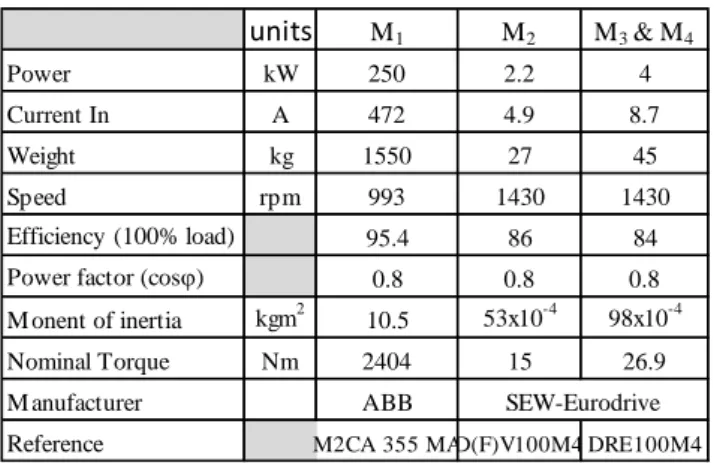
According to this, the selected motor to drive the system was an ABB motor Ref. M2CA 355 MA, whose main features are listed in table II.
Table II. – Characteristic of the electric motor.
4. Control System
The electric actuators that are used in the system are controlled via a programmable logic controller (PLC). The PLC that can be used to implement this part of the system is a Siemens S7-200 with CPU 224 or equivalent. This PLC allows the expansion of both digital and analog inputs/outputs. The analog ports allow to control the electrical drives connected to the electric motors. This PLC has 10 digital inputs and 14 digital outputs. This PLC may be connected to a source of 230 V, 50 Hz and has a DC source of 24 V. The PLC receives signals from different sensors of the system or the communication network Profibus DP and processes these signals according to the algorithm previously defined and providing their signs on the output ports. Fig. 9 shows the simplified scheme for the connections to this PLC.
Fig. 9. Simplified scheme of the integration of the sensors with the PLC.
The variables used in the programming of the PLC are: S4- Stop
S5- Start
S6 - Button: Open the front door
S7- Button: Close the front door
S8- Button: Open the back door
S9- Button: Close the back door
S10- Security key: Hydraulic pump
S11- Operating Mode Selection
Q2- Thermic relay of the transformer 230V/24V
Q3- Thermic relay of the motor M1
Q4- Thermic relay of the motor M2
Q5- Thermic relay of the motor M3
Q6- Thermic relay of the motor M4
K4- Contactor: motor M2
K7- Contactor: motor M1
K8 - Contactor: motor M3
K9- Contactor: motor M4
Y1x1- Electrovalve: Direct direction of the front door
Y1x3- Electrovalve: Inverse direction of the front door
Y2x1 - Electrovalve: Direct direction of the rear door
Y2x3- Electrovalve: Inverse direction of the rear door
VF1- Electrical drive for motor M1
VF2- Electrical drive for motor M2
VF3- Electrical drive for motor M3
VF4- Electrical drive for motor M4
S1 - Detector: Front Door
S2- Detector: Back Door
S3- Detector of presence of the sieve
Stop - Emergency stop
5. Conclusion
In this work it was presented the development of a system for the usability of forest residue biomass for electric energy production. The proposed system essentially consists in three very distinct parts, the mechanical, the hydraulic and the electric. The mechanical part is responsible by the fragmentation of forest or industrial residues. The hydraulic system is designed to drive the four hydraulic jacks, two in the front door and two in the
units M1 M2 M3 & M4 Power kW 250 2.2 4 Current In A 472 4.9 8.7 Weight kg 1550 27 45 Speed rpm 993 1430 1430 Efficiency (100% load) 95.4 86 84
Power factor (cosj) 0.8 0.8 0.8
M onent of inertia kgm2 10.5 53x10-4 98x10-4
Nominal Torque Nm 2404 15 26.9
M anufacturer ABB
Reference M2CA 355 MAD(F)V100M4 DRE100M4
rear door. Finally, the electric system comprises four electric motors. These motors are used to provide mechanical energy to the cylinder that fragments the biomass and to the belts.
The proposed solution can be a step forward among the biomass processing systems since it accepts mixed residues of different sizes and shapes, and may allow to skip pre-processing fragmentation.
This solution focused over various areas of planning, however some of them were not extensively explored and has to be tested outside the virtual environment. An endurance test of the material regarding the fragmentation is essential for the determination of the load torque, and hence the choice of the main engine.
Furthermore, the electrical system can be completed with a level sensor mounted on the inner wall of the grinding compartment, an inductive sensor mounted on the shaft of the cutting cylinder and an inductive sensor mounted on the shafts of the drums of the conveyor belts. Nevertheless the developed machine fulfill the requirements that initially was predicted, thus its design can serve as a starting point for the construction of a testing prototype.
Acknowledgement
This work was supported by national funds through Instituto Politécnico de Setúbal and Fundação para a Ciência e a Tecnologia (FCT) with reference UID/CEC/50021/2013.
References
[1] M. A. Lamoureux. “Electricity Production and Greenhouse Gas Emissions”, IEEE Power Engineering Review Vol. 22, Issue 11, pp. 22-24Nov. 2002.
[2] S. Pérez, C.J. Renedo, D. Silió, A. Ortiz, M. Mañana, “Potential Production of Electrical Energy from Forest Biomass in the North of Spain: Cantabria”, International Conference on Renewable Energies and Power Quality’05, Zaragoza, March 2005.
[3] S. Pérez, C.J. Renedo, A. Ortiz, M. Mañana, F. Delgado, C. Tejedor. “Energetic density of different forest species of energy crops in Cantabria (Spain)”, Biomass and Bioenergy, vol. 35, Issue 11, pp. 4657-4664, November 2011.
[4] P. Hakkila. “Utilization of Residual Forest Biomass”, Springer Series in Wood Science, 1989.
[5] Sh. Karaj, T. Rehl, H. Leis, J. Muller. “Analysis of biomass residues potential for electrical energy generation in Albania”, Renewable and Sustainable Energy Reviews, vol. 14, pp. 493-499, 2010.
[6] A. Pyasi, S. Deng, V. M. Thomas. “Biomass Forwards and Futures Market to Support Bioenergy Development”, IEEE Energy 2030 Conference, pp. 1-6, November 2008.
[7] J. Dai, Jun-Jian Wang, A. T. Chow, W. H. Conner. “Electrical energy production from forest detritus in a forested wetland using microbial fuel cells”, GCB Bioenergy, vol. 7, Issue 2, pp. 244-252, March 2015.
[8] J. Palma, “Accionamentos Electromecanicos de Velocidade Variável”, Fundação Calouste Gulbenkian, ISBN: 972-31-0839-9, 1999.