Daniel João Pires
de Mendonça Silva
Estratégias de entrecruzamento para melhoria
das propriedades de membranas proteicas
nanofibrosas
Crosslinking strategies to improve properties of
protein-based nanofibrous membranes
Daniel João Pires
de Mendonça Silva
Estratégias de entrecruzamento para melhoria
das propriedades de membranas proteicas
nanofibrosas
Crosslinking strategies to improve properties
of protein-based nanofibrous membranes
Dissertação apresentada à Universidade de Aveiro para cumprimento
dos requisitos necessários à obtenção do grau de Mestre em Biotecnologia, realizada sob a orientação científica do Doutor José António Teixeira Lopes da Silva, Professor Auxiliar do Departamento de Química da Universidade de Aveiro
“Vem por aqui" — dizem-me alguns com os olhos doces Estendendo-me os braços, e seguros De que seria bom que eu os ouvisse Quando me dizem: "vem por aqui!" Eu olho-os com olhos lassos, (Há, nos olhos meus, ironias e cansaços) E cruzo os braços, E nunca vou por ali... A minha glória é esta: Criar desumanidades! Não acompanhar ninguém. — Que eu vivo com o mesmo sem-vontade Com que rasguei o ventre à minha mãe Não, não vou por aí! Só vou por onde Me levam meus próprios passos... Se ao que busco saber nenhum de vós responde Por que me repetis: "vem por aqui!"?
o júri
presidente Prof.ª DoutoraLuísa Alexandra Seuanes Serafim Martins Leal
Professora Auxiliar do Departamento de Química da Universidade de Aveiro
Prof. Doutor José António Teixeira Lopes da Silva
Professor Auxiliar Departamento de Química da Universidade de Aveiro
Doutora Paula Alexandrina de Aguiar Pereira Marques
Equiparada a Investigadora Principal do Centro de Tecnologia Mecânica e Automação (TEMA) da Universidade de Aveiro
Agradecimentos Venho em primeiro lugar agradecer ao meu orientador Professor José António Lopes da Silva por esta jornada de descoberta e criação, e por toda a paciência, atenção e consideração.
Agradeço também àqueles que colaboraram comigo para a realização de processos técnicos ao longo do trabalho, nomeadamente: Dra. Manuela Marques, Departamento de Química, pela realização da Análise Elementar; Tiago Silva, Departamento de Engenharia de Materiais e Cerâmica, pela a análise SEM; Dr. Igor Bdikin, Departamento de Mecânica, pela a análise AFM.
Por último e igualmente importante, agradeço a toda a rapaziada e familiares que foram estando presentes.
palavras-chave Nanofibras, electrofiação, gliadina, biopolímeros, ligações-cruzadas, calor, genipina, ácido cítrico, eco-amigável
resumo O objetivo deste estudo foi desenvolver uma matriz nanofibrosa e ecológica de gliadina de trigo para ser submetida e testada a agentes de reticulação alternativos, calor, genipina, ácido cítrico e o convencional e tóxico glutaraldeído, de modo a que as conhecidas limitações estruturais e de resistência mecânica de fibras proteicas pudessem ser ultrapassadas, nomeadamente quando utilizadas em ambiente aquoso. Nanofibras lisas, bem definidas e sem grânulos de gliadina, com um diâmetro médio de 665 nm, foram produzidas por eletrofiação a uma concentração otimizada de 30% de gliadina (m/v), utilizando como solvente uma mistura de ácido acético/etanol. A maioria dos métodos de reticulação testados não conduziu a resultados satisfatórios, no que respeita à obtenção de membranas nanofibrosas de gliadina que preservassem a sua integridade estrutural e porosidade quando em contacto com a água. O procedimento de reticulação por calor não teve um impacto significativo nas propriedades das fibras, as quais continuaram solúveis em água.Em contraste, a capacidade resistência à água das membranas foi aumentada através de genipina, glutaraldeído e ácido cítrico, mas apenas a combinação de genipina e calor, a 120ºC, foi capaz de manter ligeiramente a estrutura porosa e fibrosa da matriz proteica. O tratamento com genipina a uma concentração de 5% (m/m) permitiu obter membranas com propriedades mecânicas melhoradas. O tempo de reação entre genipina e a proteína, assim como o tempo de maturação após eletrofiação, revelaram-se parâmetros importantes para o aumento da tolerância à água e melhoria das propriedades mecânicas. O tratamento a 120ºC tornou as fibras mecanicamente melhores, destacando-se aquelas tratadas com uma concentração de genipina de 5% após um tempo de armazenamento de um mês e aquelas tratadas com uma concentração de genipina de 10%. O tratamento tradicional com vapor de glutaraldeído resultou em fibras com uma capacidade de alongamento significativamente maior e com um aumento de força à rutura, embora o aumento do tempo de reação leve também a um significativo encolhimento da membrana e aumento da sua rigidez.
keywords Nanofibers, electrospinning, gliadin, biopolymers, crosslinking, genipin, citric acid, heat, eco-friendly.
abstract The aim of this study was to develop an eco-friendly gliadin electrospun nanofibrous matrix and its appropriate crosslinking to improve mechanical properties and water resistance. Smooth, well-defined and beadless gliadin nanofibers, with an average diameter of 665 nm, were produced by electrospinning at an optimized concentration of 30% gliadin (w/v), using a mixture of acetic acid/ethanol as the solvent. Different crosslinking methods have been tested, such as heat, genipin, citric acid, and the conventional and toxic glutaraldehyde. Most of the crosslinking methods tested did not lead to satisfactory results in obtaining gliadin nanofibrous membranes that preserved their structural integrity and porosity when in contact with water. The heat-crosslinking procedure did not have a significant impact on the properties of the fibers, which remained soluble in water. In contrast, the water-resistance ability of the membranes was increased through the treatments with genipin, glutaraldehyde and citric acid, but only the combination of genipin and heat treatment at 120 °C was able to slightly maintain the porous and fibrous structure of the protein matrix. Treatment with genipin at a concentration of 5% (w/w) allowed obtaining membranes with improved mechanical properties. The reaction time between genipin and the protein, as well as the time of maturation after electrospinning, were important parameters for water tolerance increase and improvement of the mechanical properties. The treatment at 120 °C increased the fibers mechanical resistance, especially those treated with a concentration of 5% genipin after a storage time of one month and those treated with 10% genipin. The traditional treatment with glutaraldehyde vapor resulted in fibers having significantly greater elongation and increased strength at break, although the increase in reaction time also lead to significant membrane shrinkage and increased stiffness.
Preface
Dear fellows, friends and respectful people, I present to you, without any more delays: ”Crosslinking strategies to improve properties of protein-based nanofibrous membranes”. The result of an entire academic year, under the academic guidance of Professor António Lopes da Silva.
The objective of this present work lies in the development of a protein-based fibrous membrane and consequent comparative study of crosslinking approaches, that aim to enhance their mechanical, structural and water stability properties, so that a better and sustainable substitute fibrous matrix can be produced to compete with those non eco-friendly. Fibrous gliadin mats, were obtained through the electrospinning technique, with a previous extraction of gliadin protein from wheat gluten. The subsequent crosslinking treatments are based on the use of genipin, heat, citric acid and the traditional glutaraldehyde.
Written in chapters this thesis is divided into five main parts: the first, the introduction, will provide a bibliographic review on the electrospinning world, meaning the theoretical know-how and the latest developments, innovations, and applicability, focusing on a sustainable and ecological policy, namely biopolymers and eco-friendly processes. It follows by second part, ”Materials and Methods”, with a description of all laboratory methods progressively employed, in order to achieve the proposed global objective. A third and fourth part, will contemplate the obtained results, with an analysis and discussion, as well as the achieved conclusions, respectively. The chapter “Future Objectives” closes the approached and explored theme in this thesis, with future considerations and opportunities.
Making a personal contextualization to the dear reader, about the unfolding of this work, in the early beginning of the academic year a challenge was set. After some minor deviations and change of objectives, the challenge was set. Yet, other changes came along the way. But for someone with the eagerness to create something from the start, “change” was something to be expected of, as part of the process. Once, during my lab time, my esteemed thesis advisor confirmed it. Because not only the scientific battle against the unknown is sometimes a difficult one to win, but in fact, this is how science is produced. As my Professor said to me that time, “Results might not appear as we would wish or expect, because it is part of the deal”. Back then, what I concluded was that, putting aside the frustration, readaptation through the change would be a necessary tool to successfully reach the end. For you, dear reader, to concretely contextualize you, my Master’s thesis theme changed from “Nanofibrous membranes for lactose removal from milk and whey” to “Crosslinking strategies to improve properties of protein-based nanofibrous membranes”. This change was a premeditated and weighted choice, reflecting the need to invest and explore more about the obtained protein fibers, knowing their limitations. Consequently, with the objective to solidify the knowledge in this matter, to pave future successful developments, an attempt has been made to overcome various technical and scientific challenges, about protein-based electrospun fibers, maintaining in the best interests an ecological mentality.
Equally important, for me, during all research process, was to be aware and respect my timeline, and therefore I would have only a year. Thus, despite my great personal satisfaction, the full potential of the project or what could still be explored or optimized, this year would pass, and would pass quickly. And that was it. Fidel Castro reminds me exactly that, when on his last know known speech, at the VII Cuban Communist Party Congress, in Havana, he realizes “Soon I will be 90. It was not the fruit of any effort, it was the whim of fate. Soon I will be like all the rest. Everybody's turn comes”.
It remains for me to thank all those, without excluding anyone, that gave me somehow any kind of contribution and made this process more dynamic, exciting and bearable. A great thank you to all of you! To the reader I wish you an excellent curiosity journey. Be aware that patience, enthusiasm, self-criticism is advised to continue reading forward, because in the end it aims to confirm answers, incite questions and even raise doubts.
I
Contents
Contents ... I List of Figures ... III List of Tables ... VI Notation ... VII List of Abbreviations ... VII
1. Bibliographic Review ... 1
1.1. Electrospinning ... 3
1.1.1. Historic and Current Background ... 3
1.1.2. Theoretical Principles ... 7 1.1.3. Mechanical Setup ... 8 1.1.4. Controlling Parameters………... 9 1.1.4.1. Solution Parameters ... 10 1.1.4.2. Processing Parameters ... 12 1.1.4.3. Ambiental Parameters ... 13
1.2. Biodegradable Polymers and its Applications in Electrospinning ... 14
1.2.1. Synthetic Polymers ... 15
1.2.2. Biopolymers ... 16
1.2.2.1. Polysaccharides ... 17
1.2.2.2. Proteins ... 18
1.2.3. Crosslinking of Electrospun Fibers ... 22
1.2.3.1. Ecological approaches for Protein-based mats ... 26
1.2.4. Use of Green Solvents in the Process ... 31
1.2.5. Global Opportunities in the Food Industry: A Strategy for Lactose Removal ... 32
2. Materials and Methods ... 35
2.1. Materials ... 37
2.2. Extraction of Gliadin from wheat gluten ... 37
2.2.1. Elementary Analysis of Gliadin and WG Powder ... 38
2.3.1. Electrospinning System Setting ... 39
2.3.2. Preparation of gliadin solutions ... 40
2.3.3. Optimization of electrospinning parameters ... 41
2.4. Crosslinking of Gliadin Fibers ... 41
2.4.1 Crosslinking with genipin ... 43
2.4.2 Crosslinking by thermal treatment ... 43
2.4.3 Crosslinking by genipin and thermal treatment ... 43
2.4.4 Crosslinking with citric acid ... 44
2.4.5 Crosslinking by glutaraldehyde vapor ... 44
2.5. Characterization of the electrospun fibrous mats ... 45
2.5.1. Fiber Morphology ... 45
2.5.2. Swelling Degree ... 46
2.5.3. Contact Angle ... 47
2.5.4. Mechanical Properties ... 48
2.5.5. Statistical Data ... 49
3. Results and Discussion ... 51
3.1. Development and Optimization of Gliadin Electrospun Mats ... 53
3.1.1 Gliadin extracted powder ... 53
3.1.2 Preliminary evaluation of the concentration effect in glacial acetic acid ... 53
3.1.3 Concentration effect ... 56
3.2. Crosslinking of Gliadin Fibers ... 62
3.2.1 Fiber morphology ... 62
3.2.2 Aqueous behavior: Stability, swelling degree and contact angle ... 70
3.2.3 Mechanical properties ... 81
4. Conclusion ... 87
5. Future Objectives ... 91
III
List of Figures
Figure 1 – Fibers in a Spider web [1] ... 3
Figure 2 – Characterization of fibers according its diameter [2] ... 4
Figure 3 – Scopus keyword search “electrospinning”, for articles, until 2017. A) Published articles by year - approximately after 2000 there was an exponential increase in publications; there was a slight decrease from 2015 to 2016. B) Published articles by country/territory – China is the leader in publishing articles on electrospinning, followed by United States; Portugal published so far 148 articles [21] ... 6
Figure 4 – Scopus keyword search “electrospinning”, for articles, until 2017. Published articles by subject area – The leading subject area of publishing on electrospinning is Materials Science, followed by Chemistry, and then Engineering [21] ... 6
Figure 5 – Observational experiments of electrospun fiber formation process. A) Deformation of a pending droplet by electric fields. B) Cone-shaped droplet and rectilinear jet region, at elevated electric fields. C) Looping trajectory of the jet. D) Deposition of the fiber in a collector (Adapted) [1]. ... 8
Figure 6 – Illustration showing electrospinning mechanical setup and process (Adapted) [22] ... 9
Figure 7 – Process of increasing viscosity to obtain fine and beadless fibers: A-D) Illustrations; E–H) Scanning Electron Microscope (SEM) micrographs, showing its increasing viscosity values [22] ... 11
Figure 8 – Increasing the electric field can lead to a cone deformation: A) ideal cone shape; B–D) strong deviations on the cone shape, resulted of a higher voltage [30] ... 12
Figure 9 – Categorization of biodegradable polymers into two families (natural polymers and synthetic polymers), which one of those divided into two groups [23] ... 15
Figure 10 – Example of some biopolymers and their comparative properties [68] ... 16
Figure 11 – SEM micrograph of electrospun fibers of wheat gluten low MW Fraction. A) Fibers obtained were not uniform or smooth. B) Fibers without fine definition at a higher magnification [119] ... 20
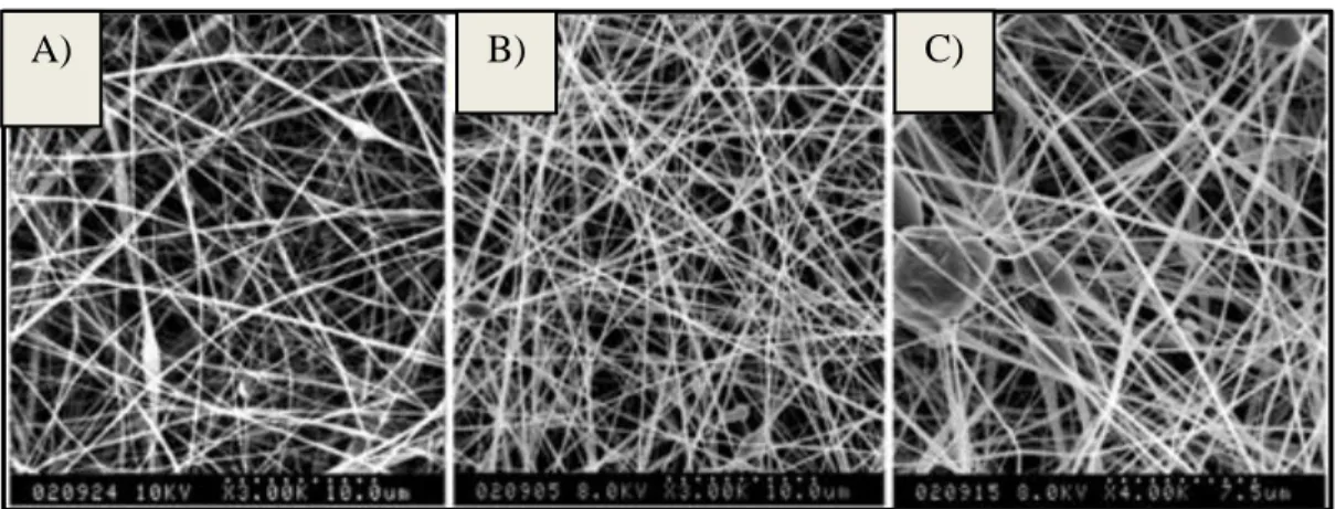
Figure 12 – SEM micrograph of electrospun fibers prolamins at their optimized concentrations. A) Hordein nanofibers (150 mg/mL). B) Gliadin nanofibers (200 mg/mL). C) Zein nanofibers (300 mg/mL) [121] ... 21
Figure 13 - SEM micrograph of zein electrospun fibers, without any treatment. A) Zein fibers at 2000X. B) Zein fibers after wetting with water and drying (Adapted) [130]. ... 22
Figure 14 – Illustration of crosslinking methods applied in biopolymers electrospun fibers. A) Chemical crosslinking. B) Physical Crosslinking. C) Enzymatic crosslinking [129]. ... 25
Figure 15 – Crosslinking reaction mechanism of genipin with primary amine groups to form the genipin blue-pigment [155]. ... 27
Figure 16 – SEM micrographs of crosslinked silk fibroin/hydroxybutyl chitosan after wetting with water. A) Genipin treated fibers for 48h. B) Glutaraldehyde treated fibers for 24h. C) Ethanol treated fibers for 24h (Adapted) [158]. ... 28
Figure 17 – Crosslinking effect of CA on zein spun fibers, 26% (w/w) zein. A) Effect of CA concentration on the tenacity. B.1) Non-crosslinked after washing and drying; B.2) Crosslinked after washing and drying; 6% (w/w) CA and 3.3% (w/w) sodium hypophosphite monohydrate (Adapted) [169]. ... 30
Figure 18 – Crosslinking interactions between proteins amine groups reacting with citric acid carboxyl groups, to form amide linkages [175]. ... 31
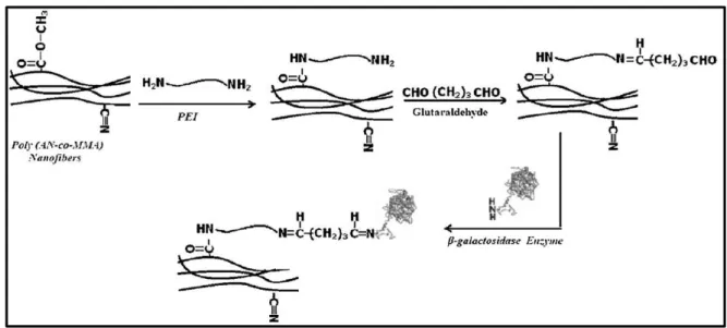
Figure 19 – Illustration of the process treatment of electrospun fibers. Modification of the matrix surface with addition of spacer-arms (PEI), with posterior treatment with glutaraldehyde to introduce functional groups for covalent bounding with immobilized β–galactosidase [194] ... 34
Figure 20 – SEM micrographs, at 5000X magnification, of electrospun nanofibers immobilized with β– galactosidase: A) Normal immobilized spun fibers. B) Immobilized spun fibers, stored at 4ºC, 15% relative humidity, for 4 weeks. C) Immobilized spun fibers, stored at 4◦C, 70% relative humidity, for 4 weeks [195]. ... 34
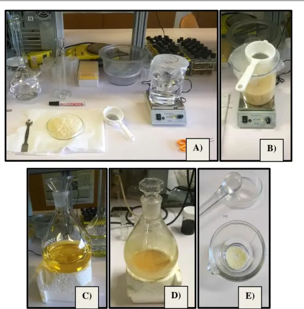
Figure 21 – Gliadin extraction from commercial gluten powder. A) Dispersion preparation; B) Dispersed gluten in ethanol 70% (v/v); C) Yellowish supernatant obtained after centrifugation; D) Viscous gliadin-rich fraction
after rotary evaporation; E) Final dried protein powder. ... 38 Figure 22 – Working laboratorial electrospinning setup, in the hotte. A) Syringe pump (on the center); rotating drum (on the right); rotating speed regulator (on the left). B) Voltage power supplier that connects to the tip of
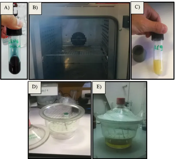
the needle syringe and to the rotating drum. ... 39 Figure 23 – Crosslinking approaches. A) Genipin spinning solution, prepared overnight, with a characteristic
blue coloration. B) Yellow whitish 9% CA solution, after a reaction time of 48h. C) Fibrous membranes placed inside the venting oven. D) Preparing desiccator with a metallic net support for fibers. E) Sealed desiccator, in
the hotte, already containing fibers and the yellowish 50% GLU solution, in the bottom. ... 45 Figure 24 – Sputter-coated fibrous samples with a thin layer of gold. ... 46
Figure 25 – Controlled ambient, at 25ºC, with constant smooth agitation, where fibrous samples are hydrating for 24h, to determine the swelling degree. ... 47 Figure 26 – Contact angle measurements using deionized water. A) Contact angle equipment (Dataphysics contact angle system OCA-20). B) 5 µl water drops (sessile drop). C) Fiber mat sample over a cover glass, in the testing plate, with water drops on the surface, during tests. ... 48 Figure 27 – Mechanical tests of membranes on a texturometer (model TA.Hdi, Stable Micro Systems, England). A) Mounted equipment ready to begin tensile trails. B) Close image of the two fixed metal grips, aligned vertically, with a grip length separation of 50 mm. C) Close image of membrane strip attached vertically under tension. D) Close image of sample rapture cause by a uniaxial tensile strength, during the test ... .49 Figure 28 – Gliadin solutions, in 100% acetic acid, with increasing protein content: 10%, 20%, 40%, 60% gliadin (w/v) (from the left to right). test ... .52 Figure 29 – Photographs taken on the produced fibers from gliadin spinning solution from 10 to 45% (w/v). Images from B) to L) are taken at the OM at 1000X magnification. A) Collected spun mat of 20% gliadin in the aluminum foil. B) Electrospraying generated from 10% gliadin. C) Electrospraying generated from 15% gliadin. D) 20% gliadin fibers, where is it possible to observe beads (red circle). E) 25% gliadin fibers, where is it also possible to observe beads, although less (red circle). F) 30% gliadin fibers, with even fewer beads (red circle). Possible to observe branched fibers (brown circle). G) 35% gliadin fibers. H) Larger and irregular fibers from 40% gliadin. I) Larger and irregular fibers from 45% gliadin, also some visible branched fibers (brown circle). J) Close-up image of 20% gliadin fibers. Visible beads (red circle). K) Close-up image of 30% gliadin fibers. Visible beads (red circle). L) Close-up image of 40% gliadin fibers. Visible branched fibers (brown circle). . .55 Figure 30 – 25% Gliadin spinning solutions. A) Gliadin dissolution in acetic acid/deionized water, 85:15, 70:30 and 50:50 (from the left to the right). B) Gliadin dissolution in acetic acid/ethanol, 85:15, 70:30 and 50:50 (from the left to the right). C) Gliadin dissolution in acetic acid/ethanol/deionized water mixtures, 70:15:15 and 50:25:25 (from the left to the right). ... .57 Figure 31 – Photographs taken from optical microscope observations (at 1000X magnification) for electrospun fibers from the 25 % gliadin spinning solution: A) Solvent mixture = 85% Acetic Acid and 15% Water. Presence of beads marked in a red circle. B) Solvent mixture = 70% Acetic Acid and 30% Water. C) Solvent Mixture = 50% Acetic Acid and 50% Water. D) Solvent Mixture = 85% Acetic Acid and 15% Ethanol. Presence of beads marked in a red circle. E) Solvent Mixture = 70% Acetic Acid and 30% Ethanol. F) Solvent Mixture = 50% Acetic Acid and 50% Ethanol. G) Solvent Mixture = 70% Acetic Acid, 15% Water and 15% Ethanol. Presence of beads marked in a red circle. H) Solvent Mixture = 50% Acetic Acid, 25% Water and 25% Ethanol. I) Close-up image of the fibrous network, using 50% Acetic Acid and 50% Ethanol, at 100X magnification. Multiple solution drops visible (brown circle). ... 59 Figure 32 – Photographs of the produced fibers from the gliadin spinning solution, at the OM, at 1000X magnification. A) 30% Gliadin. Solvent Mixture = 85% Acetic Acid and 15% Ethanol. B) 30% Gliadin. Solvent Mixture = 70% Acetic Acid and 30% Ethanol. Visible branched fibers (brown circle). C) 35% Gliadin. Solvent Mixture = 85% Acetic Acid and 15% Ethanol. Visible branched fibers (brown circle). D) 35% Gliadin. Solvent Mixture = 70% Acetic Acid and 30% Ethanol. Visible branched fibers (brown circle). ... 60 Figure 33 – Micrographs of gliadin fibers at their optimized concentration. A) SEM at 1000X magnification. B) SEM at 5000X magnification. C) SEM at 50000X magnification. D) Topography AFM image. E) Topography AFM image, with higher amplification. ... 61 Figure 34 - Topography AFM image of gliadin fibers at their optimized concentration ... 62 Figure 35 – Photographs of uncrosslinked and heat-induced crosslinked fibers, at the OM, at 1000X
V Figure 36 – Photographs of uncrosslinked and heat-induced crosslinked fibers, at the OM, at 1000X magnification. A) G30. B) T60_O. C) T120_O. ... 64 Figure 37 – Micrographs of G5_O fibers. A) SEM at 1000X magnification. B) SEM at 5000X magnification. C) SEM at 15000X magnification. D) Topography AFM image. E) Topography AFM image, with higher amplification. ... 65 Figure 38 – Topography AFM image of G5_O fibers. ... 65 Figure 39 – Photographs of genipin and heat crosslinked fibers, from OM observations. A) G2.5_O120, at 1000X magnification. B) G5_O120, at 1000X magnification. C) G5_OM120, at 1000X magnification. D) G7.5_O120, at 1000X magnification. G) G10_O120, at 1000X magnification. F) Close-up image of G5_O, at 400X magnification. Brown solution drop noticeable ... 66 Figure 40– Photographs of glutaraldehyde crosslinked fibers, from OM observations, at 400X magnification. A) GLU2. B) GLU4. C) GLU24. ... 67 Figure 41– SEM Micrographs of GLU4 fibers. A) At 1000X magnification. B) At 5000X magnification. C) At 25000X magnification. Figure 42 – Elementary analysis spectrum of GLU4 fibers by SEM-EDS. ... 67 Figure 42 – Elementary analysis spectrum of GLU4 fibers by SEM-EDS ... 68 Figure 43 – Photographs of citric acid crosslinked fibers from OM observations. A) CA9, at 50X magnification. Visible grains (red circle). B) CA5, at 1000X magnification. C) CA9, at 1000X magnification. D) CA13, at 1000X magnification ... 69 Figure 44 – SEM Micrographs of CA13 fibers. A) At 1000X magnification. B) At 5000X magnification. C) At 15000X magnification. ... 69 Figure 45 – Elementary analysis spectrum of CA13 fibers by SEM-EDS. ... 70 Figure 46 - Colorimetric mapping of Carbon (C), Sodium (Na) and Nitrogen (N) elements in the CA13 crosslinked sample. ... 70 Figure 47 – Photographs of genipin and heat crosslinked fibers, from OM observations at 1000x magnification. A) G2.5_O120. B) G5_O120. C) G5_OM120. D) G7.5_O120. G) G10_O120 ... 77 Figure 48 – Tensile strength (MPa) of crosslinked and uncrosslinked gliadin fibers. Full bars represent mean and respective tracing bars represent the standard error of the mean of 10 samples. Results data labeled with different letters exhibit statistical differences, considering p-values<0.05. ... 82 Figure 49 –Young's modulus (MPa) of crosslinked and uncrosslinked gliadin fibers. Full bars represent mean and respective tracing bars represent the standard error of the mean of 10 samples. Results data labeled with different letters exhibit statistical differences, considering p-values<0.05. . ... 82 Figure 50 – Comparison of strain (%) at breaking of crosslinked and uncrosslinked gliadin fibers. Full bars represent mean and respective tracing bars represent the standard error of the mean of 10 samples. Results data labeled with different letters exhibit statistical differences, considering p-values<0.05. ... 83
List of Tables
Table 1 – Composition of spinning solutions using different solvents and gliadin concentrations. ... 40 Table 2 – Summary description of crosslinking experimental conditions ... 42 Table 3 – Elementary analysis results and protein content for the commercial wheat gluten and the extracted gliadin ... 53 Table 4 – Solvents physicochemical properties [199-204] ... 56
Table 5 – Aqueous behavior of uncrosslinked sample G30 and heat-treated samples ... 72 Table 6 – Aqueous behavior of GEN crosslinked samples. ... 73 Table 7 – Aqueous behavior of GEN with heat crosslinked samples. ... 76 Table 8 – Aqueous behavior of GLU crosslinked samples. ... 78 Table 9 – Aqueous behavior of CA crosslinked samples. ... 80
VII
Notation
List of Abbreviations
β-Gal β-Galactosidase
AFM Atomic Force Microscopy
CA Citric Acid DMAc N,N-dimethylacetamide DMF N,N-dimethylformamide DMSO Dimethylsulfoxide EC Enzyme Commission EDC 1-Ethyl-3-(dimethylaminopropyl)-carbodiimide
EDS Energy Dispersive Spectroscopy
FDA Food and Drugs Administration
GLU Glutaraldehyde
Gal Galactose
GEN Genipin
GOS Galacto-oligosaccharide
GRAS Generally Recognized as Safe
MW Molecular Weight NHS N-hydroxysulfosuccinimide NMP N-methyl-2-pyrrolidone OM Optical microscope PCL Poly(ε-caprolactone) PEI Polyethylenimine
PEO Poly(ethylene oxide)
PGA Polyglycolide
PLA Polylactic acid
PVA Poly(vinyl alcohol)
PVP Poly(vinyl polypyrrolidone)
SEM Scanning Electron Microscope
SDS Sodium Dodecyl Sulfate
1.1. Electrospinning
1.1.1. Historic and Current Background
Fibers have been surrounding humans since the birth of the mankind. Natural fibers like cotton, silk, animal fibers - Figure 1 - or human hairs are examples of these, although the ways they are produced are different form the ones obtain artificially, as they come from a much more complex process. Our natural fibers serve expected functions, and humans have learned to use these in its favor for all sorts of applications [1].
Figure 1 – Fibers in a spider web [1].
Nowadays, there is a huge interest in fibers created artificially, mainly in nanotechnology, because of their enormous potential in a diversity of industries like aerospace, infrastructure, military, marine, consumer commodities, electronics, medical and food. For that matter, electrospinning technique started gaining great attention, because of its versatility and inexpensive way to produce nanofibers – Figure 2 – with primary applications in tissue engineering, drug delivery, fiber-based sensors, medicine, photovoltaic, filtration membranes, advanced photonic applications, wound healing, and composite materials [2]. In fact, this method is becoming the ideal to produce optimized functionalized fibers, capable of having diameters ranging from nanometers to few micrometers, from a variety of materials such as
polymers (synthetic or natural), composite materials, metals in solution or melted, ceramics and glass, with the ability of controlling the morphology, chemical and mechanical properties of the fibers, according to their purpose and research field [1,3].
Figure 2 – Characterization of fibers according its diameter [2].
The first experiments regarding electrospinning date back the late sixteenth century, by W. Gilbert who observed that charged amber would eject small droplets from a tip of a cone shape formed, when near a droplet of water. Later, in 1745 G. Bose applied electrical charges on the surface of droplets originating aerosols, and then in 1882, L. Rayleigh, studied the relation and stability of liquid jets in an electric field. The first three patents were filled in 1900 and 1902, about dispersing fluids using electrical charges, by J. Cooley and W. Morton, separately. Another advanced apparatus patent happened in July 1934, by A. Formhals, with the production of spun fibers of cellulose acetate, and in 1939, he patented a second apparatus that allowed multiples needles from the same solution, optimizing the distance between the spinning site and the collector plate [2,4]. In 60’s, Sir Geoffrey Taylor published a series of important studies, where he developed a mathematical model that helped to understand the behavior of jets produced under a given electric field: first in 1964, he studied the disintegration of drops in strong electric fields [5]; later, in 1966, Taylor reported his experiments about the force that a strong electric field exert on a conducting fluid, producing
tube, where an electric force was applied [7]. In 1971, P. Baumgarten produced electrospun fiber with less than 1 μm, from acrylic polymers, and studied the effects of solution viscosity, surrounding gas, flow rate, voltage, and apparatus geometry on fiber diameter and jet length
[8]. Later, in 1981, L. Larrondo and R. Manley produced continuous filaments from melted
polymers, such as polyethylene and polypropylene, applying an electric field [9-11]. Between 1986 and 1987, Hayati et al. published a series of studies reporting the process and movement of pendant drops and liquid stable jets, once projected, observing the effects of changing the electric field, environment and solution conductivity [12-14].
In the middle of the 90’s, an important work was presented by J. Doshi and D. Reneker, describing the production of fibers of poly(ethylene oxide) (PEO) ranging from 0.05 to 5 micron, in which they listed a number of possible commercial uses of this kind of fibers, like wound dressing materials, reinforcing materials and others; they ultimately coined this process as Electrospinning [15]. From the following years, this and others reports contributed for the increase of knowledge and the elucidation on the potential applications of electrospun nanofibers, that lead to an exponential interest in the electrospinning process by the scientific community, since 2000, as can be seen in Figure 3A [16-21]. Since then, a great number of
studies, were published, mainly in China and United States – Figure 3B - for diverse subject areas – Figure 4 - testing different set-ups and models, conditions and controlling parameters, as well as using different materials or mixtures, with a particular recent interest for biopolymers and the use of green solvents [21-24].
B)
A)
Figure 3 - Scopus keyword search “electrospinning”, for articles, until 2017. A) Published articles by year - approximately after 2000 there was an exponential increase in publications; there was a slight decrease from 2015 to 2016. B) Published articles by country/territory – China is the leader in publishing articles on electrospinning, followed by United States; Portugal published so far 148 articles
[21].
Figure 4 - Scopus keyword search “electrospinning”, for articles, until 2017. Published articles by subject area – The leading subject area of publishing on electrospinning is Materials Science, followed by Chemistry, and then Engineering [21].
1.1.2. Theoretical Principles
Electrospinning technique, because of its simple and versatile way of producing nanofibers, is the ideal approach to produce desirable 1D/3D nanostructures, in a continuous process, with a high-volume production. The generated fibers are a result of a unique, rapidly bending thread, that passes through a process of self-assembly induced by electric charges, caused by an external electric source, responsible for the repulsive Coulomb interactions between charged elements on the fluid to be spun [25,26]. However, long before fully understanding this method and the formation of the thin and defined fibers, the process was not enough controlled, and instead small particles or droplets were obtained– a process called electrospraying. The difference is related with the capacity of the produced fiber-jet being
will be the jet atomization originating electrospraying, often due to a low viscosity of the solution [2,25].
Electrostatic spinning of a polymeric solution starts after the fluid is pumped through a syringe, where in its needle is applied a certain electric charge [27]. The formation and the projection of an electrospun fiber are described according experimental and theoretical observations of the process. Firstly, a droplet forms at the tip of the syringe needle, where the electric field plays a crucial function, interacting with the charged fluid and modifying the droplet shape attached to a tip, which means that it allows the droplet (assuming a prolate shape) to become increasingly longer, as the electric field increases, forming a characteristic conical shape (Taylor cone) with a stable jet – Figure 5 A) [1,28-30]. Development of a rectilinear stable jet comes next, for a limited length - Figure 5 B), - which diameter is known to decrease as the distance from the tip increases, mostly due to solvents evaporation, but also because of the longitudinal elongation of the induced jet, identified as longitudinal force [26,30]. In the end of the straight segment, bending deformations are observed with spiraling and looping trajectories, because the jet can no longer maintain a rectilinear direction towards the collector, due to insignificantly longitudinal force, giving rise to those bending instabilities. Consequently, as the loop diameter increases, the jet becomes more stretched and narrowed, looping in itself [1,31,32]. Eventually, the solidified fiber or the projected jet reaches and deposits
on a collector, corresponding to the final step of electrospinning. The final diameter obtained is derived from both the thinning and elongation during the straight jet phase and the looping phase, but also from the solvent evaporation during those same steps. Moreover, deposition of fibers happens regardless the time of the fiber formation or even the boiling point of the solvent, however it could reflect on the morphology and characteristics of the fiber network
[26,27]. Besides, under some experimental conditions, it is possible to observe a jet branching
with multiple trajectories, during jet motion and on the fibers deposition, being this originated from electric effects [33]. Finally, it’s also important to note that gravitational force has no significant role in electrospinning [27].
Figure 5 - Observational experiments of electrospun fiber formation process. A) Deformation of a pending droplet by electric fields. B) Cone-shaped droplet and rectilinear jet region, at elevated electric fields. C) Looping trajectory of the jet. D) Deposition of the fiber in a collector (Adapted) [1].
1.1.3. Mechanical Setup
The design of electrospinning mechanical setups has been changing through the years, according with the experimental needs and objectives. The necessary equipment for a successful electrospinning process, on a laboratory scale, consists in a simple setup composed by a high voltage power supply, a syringe pump, a spinneret and a collector, as can be seen on Figure 6 [34].
It is known that the electrostatic force field is crucial on the spinning process, and thus one of the major components is a high-voltage external power supply, as referred, usually a direct current power supply, that provides an electrostatic field, ranging from a few thousands of volts to a hundred thousand of volts [22,25]. Besides that, for the process to occur a glass or plastic syringe, with a certain polymeric solution, is copulated to a flow pump system that defines a constant and controllable feed rate of the spinning fluid [25]; this arrangement can be different with for example the use of an apparatus that uses a constant pressure header tank
[34]. A spinneret, normally a metallic needle, attached to the syringe, where the solution flows
through, possesses different arrangements depending on the desired fiber conformation: a normal single spinneret, coaxial, or side by side spinneret; or multi-spinnerets, varying the axis alignment or the number of spinnerets, often used to increase the volume production [35-38]. The collector itself, a grounded conductor, can also have a variable design, which could be
a plate, or simply a sheet of aluminum foil, or even a rotating drum that is more suitable for obtaining aligned fibers, rather than randomly orientated [24,39,40].
Figure 6 – Illustration showing electrospinning mechanical setup and process (Adapted) [22].
1.1.4. Controlling Parameters
The ability to achieve desirable fibers depends hugely on the experimental parameters and on the properties of the polymers and solvents intended to produce electrospun mats. In fact, process optimization is typically a multivariate problem where several interacting variables must be taken into consideration; these controlling parameters are generally divided on solution parameters, processing parameters, and ambient parameters, and they are known to greatly influence final fiber characteristics, including their morphologies and diameters [41].
1.1.4.1. Solution Parameters
Concentration
Testing the proper concentration of a polymer solution is a crucial step, knowing that for limiting concentrations, from excessively low to too high, electrospinning process may not happen. When the concentration is low, electrospraying occurs, instead of electrospinning, given the low viscosity and high surface tension of the solution; increasing it a little further it is possible to obtain some fibers, although with beads on them, with different sizes. Using appropriated concentration smooth and fine fibers are observed; above the suitable
concentration, fibers lose definition and their diameter increase, so helix-shaped micro-ribbons fibers are usually produced [22,42,43,44].
Molecular Weight
It is possible to have the same polymer and solution concentration, under the same experimental conditions, and still obtain different fibers morphologies. That is due to molecular weight (MW) effect, which reflects in the solution viscosity; for a given concentration it is expected that the solution viscosity decreases as the polymer MW decreases; lowering the MW can result in the formation of fibers with beads, a similar effect as having a low concentration, as described above; however, increasing the MW smooth fibers are possibly obtained, and increasing it further micro-ribbon fibers are likely formed [41,45,46].
Viscosity
It is known that there is a relationship between viscosity and concentration, or even MW, which means that increasing concentration, reflects on a higher viscosity, and the same could happen with MW. Indeed, viscosity is an important factor for polymeric spinning solution, because with a very low viscosity it is not possible to observe continuous beads-free fibers, but increasing the solution viscosity usually leads to beadless and smoother fibers – Figure 7; above a certain critical viscosity, it may become impossible to perform the electrospinning process, since the fluid becomes too viscous and the applied electrostatic forces are no longer able to promote the jet formation [45-48].
A) B) C) D)
Figure 7 – Process of increasing viscosity to obtain fine and beadless fibers: A-D) Illustrations; E–H) Scanning Electron Microscope (SEM) micrographs, showing the increasing viscosity values [22].
Surface Tension
Surface tension is also a recognized important factor, attributed to solvents in the spinning solution, with a significant effect on the morphology of the electrospun fibers. It becomes the dominant factor, when the viscosity remains low and the surface tension of a solution decreases, producing then beaded fibers or just beads. Consequently, its increase may assist in the production of larger fiber. It’s essential to notice that surface tension is a variable characteristic of each solvent and that reducing it smooth fibers are likely to be obtained instead of beaded fibers [41,42,44].
Conductivity
The solution conductivity also affects the electrospinning process due to the importance of charge repulsion to stretch the polymer solution. Choosing a polymer, a solvent or salt to produce the spinning solution determine mostly of solution conductivity, because of the electronic charges of their natures, so it affects the Taylor cone formation and fiber diameter. Considering a situation where the solution charge density is not enough for the formation of the Taylor cone, under a certain electric field, increasing the solution conductivity will increase the charge on the surface of the droplet and thinner fibers may be produced [22,49,50].
1.1.4.2. Processing Parameters
Applied Voltage
The presence of a certain applied voltage, supplied by an external power supply is a major factor on electrospinning, as stated before (§ 1.1.3). It defines not only the jetting start or change process from Taylor cone, when the applied voltage is above the threshold voltage – Figure 8 - but also the final morphology of spun fibers. However, the relation between the electric field and final fiber morphology and diameter is still poor understood and discordant results have been reported; increasing voltage can increase, diminish or maintain the final fiber diameter, depending on other variables, although it is clearly a process parameter that exerts a
crucial influence on the final fibers’ characteristics [22,29,30,51-56].
Figure 8 – Increasing the electric field can lead to a cone deformation: A) ideal cone shape; B–D) strong deviations on the cone shape, resulted of a higher voltage [30].
Feed Rate
The feed rate, or flow rate, determines the volume solution within the syringe that passes through the needle to the outside, during a period of time. Normally, a higher feed rate could create unspun droplets, on the tip of needle, and also form bead fibers with larger diameters; so generally, testing with a low feed rate smooth and thin fibers are produced, which means that a balance is required between the amount of solution that leaves the tip of the needle and is ejected and the rate of replacement of the solution on the tip of the needle
[22,41,57].
Distance between the Tip of the Syringe and Collector
There’s a proven effect relation between the needle-to-collector distance and the final fibers’ diameters and morphologies. Solvent volatility is one reason for this relation, because solvent needs to evaporate so that the fibers can solidify and become thinner before depositing. On short distance, there will not be enough time for drying, and the fibers become thicker, although it all depends on the solvent volatility; moreover, for longer distances, beaded or thinner fibers can be observed [43,50,55,56,58,59]. This distance not only affects the flight time but also the electric field strength. The electric field increases as the distance decreases, which leads to an increase in jet acceleration, also contributing to hinder the solvent evaporation and to originate bead fibers and/or fusion of fibers [27,34,59].
Needle Diameter
Needle diameter can affect the final diameter of fibers, because as the orifice size is reduzed, less volume of the spinning solution is gathered at the tip, so thinner fibers are obtained and with less beads. However, a larger needle diameter can lead to formation of large droplets at the tip; or in the presence of too small orificie the solution may not be pumped through [59,60].
1.1.4.3. Ambiental Parameters
Temperature
Given that temperature has an inverse relationship with the solution viscosity: smaller fiber diameters were observed as the temperature increases. Also, higher temperatures are expected to result in an increase of solvent evaporation rate, which at the end leads to a decrease of fiber diameter [59,61,62].
Humidity
Relative humidity influences the fiber morphology mainly due to the effect on the solvent evaporation rate. Low humidity levels can rapidly increase solvent evaporation and thus contribute to a decrease of fiber’s diameter, whereas high humidity can induce a thicker diameter fiber; however this depends on the chemical nature of the polymer and other parameters discussed above [62-65].
1.2. Biodegradable Polymers and its Applications in Electrospinning
As electrospinning technology continues to grow, a lot of attention is reserved for its potential role in helping to solve environmental and energy issues worldwide. For that reason, attempts have been made to answer those concerns by designing and creating functionalized and optimized nanofibers capable of compete on global industry, to make a better and sustainable substitute for those non eco-friendly. Electrospinning has proven to be a technique with a great potential in energy fields such as on organic and hybrid solar cells, carbon dioxide capture, hydrogen storage, thermal storage, and dye-sensitized solar cells; besides that, a great initiative is being successfully made using nanofibers, in environmental fields, for liquid and air filtration, sensors, adsorbents and photocatalytic applications [66]. In addition, biomedical
and food engineering are other two major fields where extensive and promising research is being done, having in consideration an ecological side: the first one, because of biological similarity of some polymers to regulate and support cellular activities of the human tissues and organs, and for that and more being used in cosmetics, tissue engineering, drug delivery and biosensors applications; the second one, due to the fact that nanofibers might improve some food processing methods and at the same time reducing the toxicity risk of material surrounding the food or used in the food industry, with applications such as separation operations, encapsulation of food bioactive compounds or microorganisms and food sensors
[67,68].
Having this in consideration it is important to remember that the primary effort is in fact to produce electrospun fibers in a greener way, hence using biodegradable polymers, characterized for being naturally degradable, nonabrasive, nontoxic, low-cost, renewable, and eco-friendly solvents, which will be discussed below. Biodegradable polymers can be divided into two families: natural polymer (biopolymers) or synthetic polymers, according to Figure 9 [23].
Figure 9 – Categorization of biodegradable polymers into two families (natural polymers and synthetic polymers), each one of those divided into two groups [23].
1.2.1. Synthetic Polymers
In general, biodegradable synthetic polymer are divided into two groups, according to their main functional group: polyesters, such as poly(ε-caprolactone) (PCL), polyglycolide (PGA) and polylactic acid (PLA) and its copolymers; and the polyvinylics, such as the largely used poly(vinyl alcohol) (PVA) and poly(vinyl polypyrrolidone) (PVP) [23]. Because of their
characteristic nature some of them, such as PVA or PCL, have been approved by Food and Drugs Administration (FDA) for clinical or food use [68-71]. Equally important to mention, it is that that even though they are biodegradables, some synthetic polymers, PCL, polybutylene succinate and polyester amide, are petroleum‐ derived [23].
Electrospun polyester polymers are vastly used for medical applications, particularly for wound dressings and tissue engineering, because they have a great capacity to simulate the extracellular matrix, originating synthetic scaffolds (for example, skin tissue and nerve regeneration, and engineered tendons) that exhibit high wettability among cells, nontoxicity, biodegradability, structural integrity and biocompatibility [2,72-75]. Moreover, these polymers can also be employed in many other areas such as food engineering, for enzyme immobilization or for air particles filtration [76-78].
Electrospun fibers of polyvinylic polymers have a wide range of applications, which allow a great versatility in various research fields. PVA fibers, whose polymer is
water-soluble, for instance, when combined with metal, metal oxide or a mixture of other polymers, exhibit photonic functions by emitting strong light from fibers, magnetic properties and also work as dye-sensitized solar cells. Besides, among others, PVA electrospun fibers demonstrated a good result for enzymes, viruses and bacteria encapsulation, potential for wound dressing and for environmental solutions, as air particle filter [79-86]. PVP, another highly water-soluble polymer, which is frequently blended with other polymers, is used as a polymer-stabilizer of metal nanoparticles, like platinum, rhodium or gold to serve as a catalyst, and has also proven potential applications in water remediation field, wound dressing and due to antimicrobial activity when doped with metals [84,86-90].
1.2.2. Biopolymers
Biopolymeric fibers have been providing an alternative way to contest the use of non eco-friendly polymers, because not only natural polymers (some examples are shown in Figure 10) are obtained from a low-cost, renewable and ecological source, thus distancing themselves also from those petroleum‐ based biodegradable polymers, but also the electrospun fibers show very high porosity, high surface area per unit mass, adjustable mechanical properties
[23,66,91]. Furthermore, they may exhibit better fibers cytocompatibility response than those
synthetic, once that they could retain their natural cell-bindings sites [72]. Despite these facts, biopolymers could demonstrate a certain difficulty to be electrospinnable, namely polysaccharides, and spun fibers enzymatic biodegradation and their water solubility can occur naturally [72,91]. This family of polymers can be divided into Polysaccharides and Proteins – Figure 9 [23].
1.2.2.1. Polysaccharides
The list of polysaccharides already electrospun is extensive, alone or combined with other biodegradable polymers, being the biomedical area one of the most representative application areas [91].
Most polysaccharide solutions, above a certain critical concentration, show the typical shear thinning behavior, i.e., the apparent viscosity decreases as the shear rate increases. For fiber formation during electrospinning, a small shear thinning degree is usually desirable, since if there is a too pronounced decrease in viscosity due to the deformation imposed by the electric field, the spinning fluid jet on the tip of the needle breaks easily and there is no fiber formation [92].
Chitosan is a cationic polysaccharide whose application in electrospinning has been largely studied [23]. The spinning solution of chitosan can be prepared using solvents like
hydrochloric acid, acetic acid, and trifluoroacetic acid; fiber diameters ranging of 60 to 200nm were obtained with this last solvent, according different polymer MWs and concentrations
[91,93]. Synthetic polymers of PVA, PCL and PEO are commonly used to produce blended
nanofibers with this chitin-derived polymer. The majority of applications have to do with biomedical reasons, for example for prevention of wound infections and local chemotherapy, tissue engineering of liver, or even for wound dressing and anti-microbial applications
[91,94-96].
Another abundant polymer is cellulose, which due to the strong bond interactions makes the solubilization difficult in common solvents, limiting the process, so a better alternative is to use cellulose derivates, for example, hydroxypropyl methyl cellulose, ethyl cellulose and cellulose acetate [66]. Some of the functional properties of these biopolymer electrospun fibers have been applied for tissue engineering of bone, water remediation for removal of heavy metals, anti-microbial and enzymatic immobilization [91,97-99].
Dextran is another natural material where smooth electrospun fiber can be produced ranging hundred nanometers to few micrometers [100]. Various solvents are used in particular water, but mixture of dimethylsulfoxide (DMSO)/N,N-dimethylformamide(DMF) and DMSO/water as well [91]. Blended nanofibers of dextran and antibacterial compounds showed high antimicrobial activity against gram positive and negative bacteria, and exhibited useful applications as wound dressings [101,102].
Starch, alginate, pullulan and cyclodextrin are some of other few polysaccharides that can be used to obtain fine electrospun fibers; nevertheless, the list of polysaccharides for
electrospinning continues to grow, and future developments are expected in this area [91].
1.2.2.2. Proteins
Protein can be used as a natural source to obtain functional biomaterials, and according to the source, they can be categorized as animal proteins, such as whey protein, collagen, gelatin and casein, or plant protein, like soy protein, wheat, or canola [23]. In general, the physical and chemical properties of proteins (namely globular proteins, which are typically soluble in water or in acid/base aqueous solvents, and fibrous proteins, water insoluble) are related with the kind of amino acid residues existing and their position on the polymer chain
[103]. Because of their stable 3D structure, due to hydrogen bonding and hydrophobic
interactions, or even disulfide bonds, it may be necessary to partially unfold proteins to allow for molecular reorientation and to make them suitable to produce biomaterials [23,103]. Therefore, it may be required to choose proper solvents, might them be aqueous acids or bases, the use of heat or the addition of denaturating agents [91]. In the same way as polysaccharides,
protein fibers alone show some problems related with mechanical strength and aqueous media stability, so they are frequently combined with other polymers, mainly biodegradables ones, or there is the need to perform some kind of post-electrospinning treatment, namely cross-linking, as will be discussed in section § 1.2.3.[91].
Prolamins are among the proteins most used so far to obtain electrospun nanofibers, such as zein, hordein, glutenin and kafirin, from maize, barley, wheat and sorghum, respectively [104-107]. Generally and according to their solubility, cereal plant proteins are classified into albumins, globulins, prolamins and glutelins, being the prolamins soluble in aqueous alcohol solutions (70–90%), and characterized by high content of proline and glutamic acid. Depending on the cereal, the prolamin content is variable between 35-50% of all protein content, in wheat, barley, maize, and sorghum [108,109]. Among prolamins, zein has been the most studied to produce electrospun nanofibers, using solvents like ethanol, isopropanol, acetic acid or even DMF. Characteristics as biodegradability and biocompatibility brand this once low-valued material as a versatile electrospinnable polymer capable of providing new resources for biomedical applications, mostly by mixing with other biodegradable polymers, e.g. zein-collagen fibrous membranes for wound healing[111], polyurethane–cellulose acetate–zein antibacterial composite mats[112] and fluorescent
Although with fewer research studies published, hordein shows less cytotoxicity than zein, plus nanofibrous membranes from this biopolymer showed attractive characteristics as flexible materials with temperature sensing properties for sensors and electronic devices, and when combined with zein, as useful nonadherent biocompatible materials for controlled drug delivery in wound dressings and other applications [105,114-117].
Wheat (Triticum spp.) is one of the most cultivated cereals, since the beginning of human civilization, compose by 60-80% starch and 7-22% storage proteins. Wheat proteins are recognized to be influenced by plant genotype and environmental factors, and are responsible to form the visco-elastic dough. These proteins are known as gluten proteins corresponding to the grain storage protein fraction and comprising around 80-85% of total wheat proteins. Gluten can be divided into two functional groups of proteins: gliadins that contribute to dough cohesiveness, softness and extensibility, therefore conferring viscous behavior; and glutenins responsible for dough hardness and elasticity [108,118]. The first successful study regarding the production of electrospun nanofibers from gluten is dated 2005, but other studies have since appeared using gluten alone or blended with PVA, using solvents such as 1,1,1,3,3,3-hexafluoro-2-propanol, ethanol/2-mercaptoethanol or water/1-propanol. The presence of disulfide bonds in gluten proteins makes wheat gluten not suitable for a direct electrospinning from aqueous dispersions, therefore the use of solvents like 1,1,1,3,3,3-hexafluoro-2-propanol or 2-mercaptoethanol increases wheat gluten solubility, as well as thiolated additives as reducing agents [119-124]. Gluten-based nanofibers have shown interesting properties, for example antimicrobial activity against Staphylococcus aureus when blended with PVA and zirconia, and incorporated with nisin, controlled prolonged-release of certain polar compounds such as urea, or as efficient low-cost adsorbents in aqueous environments to remove and recover metal nanoparticles, also when combined with PVA [122-124].
Glutenins, part of the referred wheat gluten protein fraction, are recognized as a heterogeneous protein mixture, whose MW ranges between 80000 and several million Da [108]. This electrospinnable protein has great water stability, due to the extensive inter- and intra-crosslinking by disulfide bonds, due to the elevated presence of cysteine. For this reason, sodium dodecyl sulfate (SDS) is often added to the spun dope to decrease the degree of S-S bonding, thus allowing a better spinning solution to be obtained. Hence, PVA nanofibers have been prepared using glutenin as an additive to improve elasticity. In addition, wheat glutenin was used to produce a promising 3D electrospun nanofibrous structure for adipose tissue engineering [108,125,126].
Gliadins
Gliadins are also wheat gluten prolamins, whose MWs are defined between 30000-80000 Da, and represents circa of 40-50% of the total storage proteins. As well as glutenins, however differently, gliadins contain disulfide bonds, in particular intra-molecular on α-, β-, and γ –gliadins, but no S-S bonds at all on ω-gliadins. The different macromolecular organization and intra- and intermolecular interactions are responsible for different solubility, and contrarily to glutenins, gliadins are soluble in aqueous alcohols. Gliadins are also rich in proline and glutamine, and when solubilized in 70% aqueous they adopt a globular shape [127].
The first fruitfully attempt for obtaining electrospinnable fibers made from gliadin used an acetic acid extracted protein fraction from commercial wheat gluten. Fibers obtained ranged from 100 nm to 5 μm. However, fine and smooth fibers were not obtained (Figure 11), probably due to the too low polymer concentration and/or because the protein extract was rich mainly in low MW gliadins [119].
Gliadin nanofibers were also successful produced using hybrid organic–inorganic molecules (polyhedral oligomeric silsesquioxane) as nanofillers to improve fiber properties. Comparing gliadin with gluten fibers, the first showed better, smother and thinner fibers (average diameter 222±12 nm) than gluten (diameter around 460 nm). Thinner fibers, although presenting some beads, but also higher jet instabilities were obtained due to the presence of the fillers [128].
Figure 11 - SEM micrograph of electrospun fibers of wheat gluten low MW fraction. A) Fibers obtained were not uniform or smooth. B) Fibers without fine definition at a higher magnification [119].
A major study was made to compare three prolamins for electrospinning: zein, hordein B)
proteins, which were all alcohol-extracted. Analyses showed that hordein and gliadin have similar amino acid content, but the second one showed a higher content in cysteine of all three, and thus a higher probability to form disulfide bonds. Higher protein concentration and the increase of the amount of acetic acid in the mixed solvent led to an increase of solution viscosity, with hordein exhibiting the most viscous solution and zein the least. It was proposed that the optimized concentration, using acetic acid 100% as the solvent, would be 200 mg/mL for gliadin. All prolamin proteins displayed similar fiber diameters, about 200 nm, at their optimized concentrations, however morphology changed between them, as can be compared in Figure 12. It is possible to observe more uniform nanofibers using gliadin, although with some bead formations (Figure 12 B). Comparing mechanical properties, gliadin nanofibrous mats showed a higher tensile strength of all three, probably due to smaller changes in the protein secondary structures and interactions during the electro-spinning process. In terms of biocompatibility, hordein fibers exhibited much lower cytotoxicity than gliadin and zein fibers, showing gliadin fibers the highest [114].
Figure 12 - SEM micrograph of prolamins electrospun fibers at their optimized concentrations. A) Hordein nanofibers (150 mg/mL). B) Gliadin nanofibers (200 mg/mL). C) Zein nanofibers (300 mg/mL) [114].
1.2.3. Crosslinking of Electrospun Fibers
B) C)
Electrospun biopolymeric materials have been potentiating biomedical and food research, due to their ecological side and versatile properties. In the last two decades, a great emphasis has been placed on the fabrication of biomaterials based on proteins such as silk, albumin, gelatin, or cereal proteins in general. Scaffolds with ability to mimic extra cellular matrices, related to the protein cytocompatibility and biodegradability, and mats with capability of loading nanoparticles, drugs or nutraceuticals to induce their sustained released, or as nano structured supports to immobilize enzymes, are some examples [103,129].
Although protein spun fibers present themselves as a sustainable and good alternative to synthetic polymers and even other biopolymers, they typically demonstrate insufficient mechanical properties and poor stability in aqueous media or under high relative humidity conditions, often losing their fibrous and porous structure, or even dissolve or disintegrate. Figure 13 shows an example of the observed morphological and structural changes for zein electrospun fibers when in contact with aqueous medium [130]. To overcome these challenges, one way is to produce blends: mixtures of different polymeric materials provide the final blended product improved physical and structural properties, as was already shown, for example, for polyurethane/cellulose acetate/zein, amaranth protein isolate/pullulan, soy protein/lignin, or PCL/gelatin, polyurethane/gelatin and PLA/gelatin electrospun fibers
[91,112,131, 132,133].
Figure 13 - SEM micrograph of zein electrospun fibers, without any treatment. A) Zein fibers at 2000X. B) Zein fibers after wetting with water and drying (Adapted) [130].
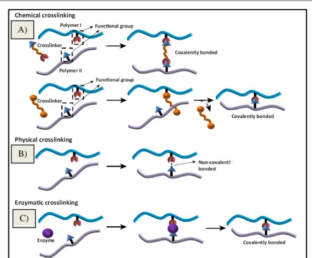
Crosslinking treatments, summarized on Figure 14, are another alternative popularly B)
structural functions, which results from the action of crosslinking agents that interconnects polymer molecules [129]. Crosslinking of proteins may result in protein interactions within the same polypeptide chain or between different polypeptide chains from the same protein, or between different proteins [134]. Crosslinking treatments have been used in the majority of all electrospinnable proteins studied so far, such as zein, wheat, soy, whey, gelatin, collagen and fibrinogen confirming the improvement of the characteristics of these fibrous materials that can be obtained by this approach [91,135-138]. For example, noncytotoxic soy protein electrospun fibers with higher fiber strength were obtained after crosslinked using 1-ethyl-3-(dimethylaminopropyl)-carbodiimide(EDC)/N-hydroxysulfosuccinimide (NHS) [139].
Crosslinking can be accomplished by enzymatic, physical or chemical methods [91]. Physical treatments, like heat-induction or UV-irradiation may introduce desired changes on the fibers. Irradiation treatments (UV, -irradiation) may cause different modifications on proteins, namely oxidation of amino acids, conformation modifications, formation of protein free radicals or establishment of covalent bonds [103,129,140]. In one report, UV radiation and genipin cross-linking were compared to immobilize collagen on the surface of electrospun poly (methyl methacrylate) nanofibers; even though the amount of collagen immobilized by genipin cross-linking was significantly higher, the UV-irradiated fibers exhibited greater potential for cellular growth and proliferation of respiratory epithelial cells [141]. Heat is
another method to induced crosslinking reactions, first through protein denaturation, then promoting interactions between peptides chains such as covalent bonds [103,136]. Heat-induced covalent crosslinking was investigated in PEO blended nanofibers, with whey proteins, specifically whey protein isolate and β-lactoglobulin, by submitting the produced fibers to temperatures above the gelation temperature of whey proteins. After one-hour treatment at 80ºC, fibers kept their fibrous structure as well as the fiber diameter, and even increasing thermal stability for the β-lactoglobulin/PEO fibers. To water insolubility impact was evaluate by immersing electrospun mats after a procedure at 100ºC for 24 to 44h, in which they prove to be water-resistant, even after days in water, thus it could be suggested the existence of a protein crosslinking caused by the β-lactoglobulin unfolding and the formation of disulfide bonds; moreover, the insolubility effect was dependent of the treatment time and sample thickness [136].
For protein-based materials, enzymatic crosslinkings can be achieved using the microbial enzyme transglutaminase (TGase), obtained commercially from Streptoverticillium
mobaraense. Also known as protein-glutamine γ-glutamyltransferase (EC 2.3.2.13), this
![Figure 2 – Characterization of fibers according its diameter [2] .](https://thumb-eu.123doks.com/thumbv2/123dok_br/16020839.1104231/28.893.280.649.273.597/figure-characterization-fibers-according-diameter.webp)
![Figure 9 – Categorization of biodegradable polymers into two families (natural polymers and synthetic polymers), each one of those divided into two groups [23] .](https://thumb-eu.123doks.com/thumbv2/123dok_br/16020839.1104231/39.893.156.773.87.444/figure-categorization-biodegradable-polymers-families-polymers-synthetic-polymers.webp)
![Figure 18 – Crosslinking interactions between proteins amine groups reacting with citric acid carboxyl groups, to form amide linkages [175]](https://thumb-eu.123doks.com/thumbv2/123dok_br/16020839.1104231/55.893.188.766.86.290/figure-crosslinking-interactions-proteins-groups-reacting-carboxyl-linkages.webp)