IEEE Proof
Web Version
Broadband UHF RFID Passive Tag Antenna
for Near-Body Applications
André G. Santiago, Jorge R. Costa, Senior Member, IEEE, and Carlos A. Fernandes, Senior Member, IEEE
Abstract—One challenge for UHF RFID passive tag design is to
obtain a low-profile antenna that minimizes the influence of near-body or attached objects without sacrificing both read range and universal UHF RFID band interoperability. A new improved de-sign of a RFID passive tag antenna is presented that performs well near problematic surfaces (human body, liquids, metals) across most of the universal UHF RFID (840–960 MHz) band. The an-tenna is based on a low-profile printed configuration with slots, and it is evaluated through extensive simulations and experimental tests.
Index Terms—Broadband, passive tag antenna, person
identifi-cation, radio frequency identification (RFID).
I. INTRODUCTION
R
ADIO frequency identification (RFID) has emerged as one of the most popular methods for asset, person, and object identification through the use of active or passive chipped tag antennas bearing a univocal identification code [1].Currently, UHF RFID passive tags present the lowest cost and cover a wider range of applications [2]. The UHF RFID frequency band of operation extends from 840 to 960 MHz divided into four world regions: (840–845 MHz) China, EU (865–868 MHz), US (902–928 MHz), and Japan (950–956 MHz) [3].
Several applications involving passive UHF RFID are pos-sible, such as patient identification, localization, and monitoring in hospitals [4]; inventory management in warehouses, super-markets, and shops; or suitcase security and tracking in airport luggage operations [5].
However, most of the UHF RFID tags are not immune to the nearby presence of metals, liquids, or the human body, which af-fect tags’ read range. Different approaches are commonly used to deal with this difficulty. Active tags are commonly used for near-body RFID: A commercial active wristband tag operating in 2.54-GHz RFID is presented in [6] for personnel localization within 100 m read range with more than 4 years of battery life.
Manuscript received November 30, 2012; accepted January 23, 2013. This work was supported in part by the Fundação para a Ciência e Tecnologia under Project RFIDLocal PTDC/EEA-TEL/102390/2008.
A. G. Santiago and C. A. Fernandes are with the Instituto de Teleco-municações, Instituto Superior Técnico, Technical University of Lisbon, 1049-001 Lisbon, Portugal (e-mail: andre.santiago.1988@gmail.com; Carlos.Fernandes@lx.it.pt).
J. R. Costa is with the Instituto de Telecomunicações, Instituto Superior Técnico, Technical University of Lisbon, 1049-001 Lisboa, Portugal, and also with the Departamento de Ciências e Tecnologias da Informação, Instituto Universitário de Lisboa (ISCTE-IUL), 1649-026 Lisbon, Portugal (e-mail: .Jorge.Costa@lx.it.pt).
Color versions of one or more of the figures in this letter are available online at http://ieeexplore.ieee.org.
Digital Object Identifier 10.1109/LAWP.2013.2243400
However, active tags are significantly more expensive at UHF than the passive alternatives.
A good RFID tag antenna example is presented in [7], based on a planar inverted-F antenna (PIFA), which is immune to the platform. In [8], a circular polarization square patch antenna is proposed for metallic surfaces with high reading ranges. Both have very narrow operation bandwidth. In [9], a bowtie slot antenna has been co-designed with an artificial magnetic con-ductor (AMC) to make the RFID tag usable with metallic ob-jects. However, the AMC more than triples the area required for a similar antenna in free space.
In [10] and [11], a novel UHF RFID passive tag configu-ration is reported for applications like human monitoring and metallic cylinder tracking. This solution is again limited to a narrow bandwidth that is tuned for the US UHF RFID band. This configuration inspired the solution presented in this letter to extend the operation to the universal UHF RFID bands, while simultaneously complying with the following requirements: ad-equate for commercial passive RFID chips, low profile, high reading range, and immune to the close vicinity of nearby ob-jects, thus advancing with respect to solutions like [7]–[11]. A preliminary configuration was analyzed in [12] through simula-tion. This letter extends the study to include extensive experi-mental characterization of the antenna along with RFID system performance tests when the antenna is assembled with a com-mercial UHF RFID chip.
II. TAGDESIGN
A tag’s read range is related to the square root of the power transmission between antenna and microchip. The power reflec-tion coefficient is related to the power transmission coeffi-cient through [13]
(1) where and are the complex antenna and microchip input impedances, respectively. To deliver the maximum power to the microchip (i.e.,
and ), the antenna impedance has to be conjugate-matched to the microchip impedance. The present antenna is op-timized to work with the commercial Alien Higgs-2 EPC Class Gen 2 chip [14]. The frequency dependence of the microchip impedance has been taken into account in the calculations using the manufacturer provided model.
When studying the influence of the human torso in all simu-lation studies ahead, this is represented by a stratified four-layer parallelepiped body model based on [15] (Fig. 1). The adop-tion of a parallelepiped shape instead of an elliptical cylinder as in [15] favors simulation speed without affecting the results.
IEEE Proof
Web Version
2 IEEE ANTENNAS AND WIRELESS PROPAGATION LETTERS, VOL. 12, 2013
Fig. 1. CST Rectangular cube model of the human torso with dielectric con-stant and conductivity for the layer tabulated at 870 MHz [15].
TABLE I
PHYSICALPARAMETERS OF THELAYEREDANATOMICALMODEL AT870 MHZ[15]
Values used for the dielectric constant and conductivity are presented in Table I for 870 MHz [15]. The antenna is positioned 2 mm away from the skin as if it was attached to the patient’s clothes.
III. ANTENNADESIGN ANDCHARACTERIZATION
The proposed antenna configuration derives from a simpler RFID tag antenna from [11] that is intrinsically narrowband and thus fails to comply with the whole world UHF RFID band. However, this is still interesting as a starting point because it is low-profile and insensitive to the body presence. The original antenna is formed by two quarter-wavelength patches shorted to the ground at the edges. For the sake of comparison to the new antenna, the original one was reproduced after slight design ad-justments: Instead of FR4 plus foam substrate used in [11], a 1.575-mm-thick Rogers RT5880 was used as sub-strate in order to improve the tag antenna efficiency and in-crease its mechanical stability. The tag parameters were reopti-mized to cope with that change and to retune it for the EU band (865–868 MHz) to make it compatible with EU RFID readers. This is onwards referred as the BTA1 antenna.
The new antenna proposed in this letter retains the two quarter-wavelength patches shorted at the longitudinal edges (by two shorting plates, SP1 and SP2). However, an internal loop is introduced as shown in Fig. 2. This loop is delimited by a 1-mm-width slot pattern that forces currents to circulate around the RFID microchip that is soldered at the central part of the loop.
With this modification, new optimization parameters are in-troduced (see Fig. 2) that allow further degrees of freedom to extend the antenna operation bandwidth. As in BTA1, the an-tenna length, width, and gap parameters determine the tag’s basic tuning to a target frequency. The additional parameters (LL, LW, LaL, and ISD) make it possible to keep the mag-nitude of the surface current near the tag feeding point from
Fig. 2. CST model for the RFID tag antenna BTA2.
Fig. 3. Comparison of simulated input impedance of both BTA antennas for near-body and in free space (Air) conditions.
changing with frequency as abruptly as in BTA1. Those param-eters control the slope of the real and imaginary parts of the input impedance curves that conjugate-matches the chip’s com-plex input impedance over a broad operation bandwidth. The final dimensions of the patches and ground are 67.5 32 and 137 32 mm , respectively. The loop length (LL) is 73 mm, the loop width (LW) is 21 mm, the loop arm length (LaL) is 50 mm, the internal slots distance (ISD) is 4 mm, and the gap is 2 mm wide. This antenna is onwards referred to as BTA2.
Simulated input impedance obtained with CST Transient Solver is presented in Fig. 3 for BTA1 and BTA2 in free space and near the body. BTA1 impedance presents very high slope versus frequency, and this cannot be improved acting on its design parameters. This result is similar to what was presented in the original papers [10] and [11]. BTA2 impedance results show less change than BTA1 inside the frequency band of interest, and the impedance values are near the microchip’s conjugate impedance. The implication on power coupling to the chip is analyzed in Section IV together with measured results.
IV. EXPERIMENTAL ELECTROMAGNETIC(EM) CHARACTERIZATION
For experimental evaluation, two copies of BTA1 and BTA2 were fabricated using a photolithographic etching procedure. BTA2 is shown in Fig. 4. One of the copies was integrated with an external balun based on [17] to enable balanced-port impedance measurements using a coaxial port vector network
IEEE Proof
Web Version
Fig. 4. Fabricated BTA2: (a) BTA2 with microchip; (b) BTA2 with balun con-nected to the VNA for near-body EM characterization.
Fig. 5. Comparison of power reflection coefficient (measurements versus sim-ulations) of BTA1 antenna for near-body and in free space (Air) conditions.
analyzer, Agilent E8361A PNA. Following appropriate port cal-ibration [17], input impedance of BTA1 and BTA2 was mea-sured both in free space and when attached to a human torso (Fig. 4).
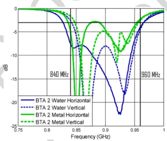
Power reflection coefficients were calculated from this data using (1). Comparison to simulations is presented in Figs. 5 and 6 for BTA1 and BTA2, respectively. There is a slight shift be-tween simulated and measured curves due to fabrication toler-ance and uncertainty of the balun’s calibration procedure. Nev-ertheless, the power reflection coefficient curves clearly demon-strate that the bandwidth of the new antenna is significantly improved and that the half-power bandwidth criterion for the entire UHF RFID band is only met by BTA2. This proves the concept, but still it is worth evaluating how BTA1 and BTA2 perform near other difficult surfaces. Impedance measurements were carried with BTA antennas attached to a water bottle and to a tin can. For a better understanding of the best tag placement on a cylindrical surface, the antennas were also characterized in two different orientations, vertical and horizontal. Power re-flection coefficient results are presented in Fig. 7. As expected, BTA2 complies with the full half-power bandwidth criterion for both objects and for both orientations.
V. RFID SYSTEMTESTS
The second copies of fabricated BTA1 and BTA2 antennas were integrated with the commercial chip Alien Higgs-2 EPC Class Gen 2. This allowed performing RFID range tests, the ultimate proof of concept. The chipped BTA antennas were mounted on the azimuth positioner of an anechoic chamber
Fig. 6. Comparison of power reflection coefficient (measurements versus sim-ulations) of BTA2 antenna for near-body and in free space (Air) conditions.
Fig. 7. BTA 2 measured power reflection coefficients for two different orien-tations (vertical and horizontal) with water bottle and metal can.
attached to Styrofoam (emulating free space), live body torso, bottle of water, and tin can. Similar tests were also performed in the same conditions with a standard Alien ALN-9640 Squiggle RFID tag in order to compare BTA range with a general-pur-pose commercial tag. Vertical and horizontal orientations were considered for all cases.
Alien circular polarization (ALR-860-AC) antenna [14] was placed in front of the target antenna at an adjustable distance from 0 to 5 m. This antenna was connected to a Sirit Infinity UHF Reader [17]. Its power attenuation was adjusted to 8 dB to ensure that the maximum detectable range could fit inside the available 4 m length inside the anechoic chamber. By changing the measurement distance and by rotating the azimuth positioner from 0 (front-to-front antenna alignment) to 180 , the edge of the detection region was found for the main planes of the antennas under test. Since these antennas are symmetrical, the same behavior is expected between 0 and .
Detection range results for 866 MHz are presented in Figs. 8–11. The larger metal area of BTA2 explains its larger range in free space since it permits to capture more energy
IEEE Proof
Web Version
4 IEEE ANTENNAS AND WIRELESS PROPAGATION LETTERS, VOL. 12, 2013
Fig. 8. RFID detection range in free space for BTA2, BTA1, and Alien tag: 8 dB power attenuation. (a) Vertical and (b) horizontal orientation.
Fig. 9. RFID detection range for body-mounted BTA2, BTA1, and Alien tag: 8 dB power attenuation. (a) Vertical and (b) horizontal orientation.
Fig. 10. RFID detection range for metal-mounted BTA2, BTA1, and Alien tag. 8 dB power attenuation. (a) Vertical and (b) horizontal orientation.
Fig. 11. RFID detection range for water-bottle-mounted BTA2, BTA1, and Alien tag: 8 dB power attenuation. (a) Vertical and (b) horizontal orientation.
from the electromagnetic waves radiated by the reader antenna. When attached to the human body, water bottle, or tin can, both BTA antennas show comparable range, but the commercial tag shows insignificant range as expected. Range similarities between both BTA antennas are explained by similar power reflection performance of the two BTA antennas at 866 MHz as seen in the measured results from Figs. 5 and 6. The results from these figures together with those from Fig. 11 demonstrate that the developed BTA antennas are fully operational. Although the RFID tests cannot be performed for other RFID subbands because the available Sirit reader is factory limited to operate only in the European subband, it is clear from the measured results of Figs. 5–7 that BTA2 will work throughout the full UHF RFID band, while BTA1 is band-limited. It is noted that using reader maximum regulated power in an outdoor open environment, BTA2 exhibits about 12 m steady range in free space and about 5 m when attached to a body torso, a water bottle, or a tin can. The Alien squiggle tag reached 6 m in free space with the same reader power, but insignificant readings were obtained when attached to the other objects.
VI. CONCLUSION
A simple, passive, low-profile RFID tag antenna is presented (BTA2) that operates near different kinds of difficult surfaces and in free space, keeping the compatibility with most of the universal UHF RFID band from 840 to 960 MHz (13.3% band-width). The tag bandwidth is of the order of 17% in free space and about 13.7% when attached to the human body torso, with read ranges about 5 m. The broadening of the tag operation band was obtained by the introduction of appropriate slots in the top metallization of the antenna to control the slope of the real and imaginary parts of its input impedance to better match the chip complex impedance. To reduce the tag cost, the antenna can be redesigned using a cheaper substrate (like FR4). However, those materials tend to have higher loss tangent than Duroid, nega-tively impacting on the tag range.
ACKNOWLEDGMENT
The authors acknowledge the collaboration from C. Brito for prototype construction and A. Almeida for prototype measurements.
REFERENCES
[1] K. Finkenzeller, RFID Handbook, 3rd ed. New York, NY, USA: Wiley, 2010.
[2] K. Rao, P. Nikitin, and S. Lam, “Antenna design for UHF RFID tags: A review and a practical application,” IEEE Trans. Antennas Propag., vol. 53, no. 12, pp. 3870–3876, Dec. 2005.
[3] Z. Chen, X. Qing, and H. Chung, “A universal UHF RFID reader antenna,” IEEE Trans. Microw. Theory Tech., vol. 57, no. 5, pp. 1275–1282, May 2009.
[4] S. Wamba and E. Ngai, “Unveiling the potential of RFID-enabled in-telligent patient management: Results of a delphi study,” in Proc. 44th
HICSS, 2011, pp. 1–10.
[5] C. Medeiros, J. Costa, and C. Fernandes, “Passive UHF RFID tag for airport suitcase tracking and identification,” IEEE Antennas Wireless
Propag. Lett., vol. 10, pp. 123–126, 2011.
[6] GAO RFID, Inc., Toronto, ON, CA, “Product overview: Ac-tive wristband RFID tag (127006),” 2012 [Online]. Available: http://www.gaorfid.com
[7] M. Hirvonen, P. Pursula, K. Jaakkola, and K. Laukkanen, “Planar in-verted-F antenna for radio frequency identification,” Electron. Lett., vol. 40, no. 14, pp. 848–850, 2004.
[8] H. Chen, S. Kuo, C. Sim, and C. Tsai, “Coupling-Feed circularly polar-ized RFID tag antenna mountable on metallica surface,” IEEE Trans.
Antennas Propag., vol. 60, no. 5, pp. 2166–2174, May 2012.
[9] R. Hadarig, M. Gomez, Y. Alvarez, and F. Las-Heras, “Novel bow-tie-AMC combination for 5.8-GHz RFID tags usable with metallic ob-jects,” IEEE Antennas Wireless Propag. Lett., vol. 9, pp. 1217–1220, 2010.
[10] T. Koskinen and Y. Rahmat-Samii, “Metal-mountable microstrip RFID tag antenna for high impedance microchip,” in Proc. 3rd Eur.
Conf. Antennas Propag., 2009, pp. 2791–2795.
[11] H. Rajagopalan and Y. Rahmat-Samii, “Conformal RFID antenna de-sign suitable for human monitoring and metallic platforms,” in Proc.
4th Eur. Conf. Antennas Propag., 2010, pp. 1–5.
[12] A. Santiago, C. Fernandes, and J. Costa, “Broadband UHF RFID pas-sive tag antenna for near-body operation,” in Proc. 3rd IEEE Int. Conf.
RFID, Technol. Appl., 2012, pp. 271–274.
[13] K. Rao, P. Nikitin, and S. Lam, “Antenna design for UHF RFID tags: A review and a practical application,” IEEE Trans. Antennas Propag., vol. 53, no. 12, pp. 3870–3876, Dec. 2005.
[14] Alien Technology, Morgan Hill, CA, USA, “Alien,” 2012 [Online]. Available: http://www.alientechnology.com
[15] G. Morrocco, “Body-matched RFID antennas for wireless biometry,” in Proc. 1st Eur. Conf. Antennas Propag., 2006, pp. 1–5.
[16] X. Qing, C. Goh, and Z. Chen, “Impedance characterization of RFID tag antennas and application in tag co-design,” IEEE Trans. Microw.
Theory Tech., vol. 57, no. 5, pp. 1268–1274, May 2009.
[17] Sirit, Inc., St. Paul, MN, USA, “Sirit,” 2012 [Online]. Available: http:// www.sirit.com
IEEE Proof
Print Version
Broadband UHF RFID Passive Tag Antenna
for Near-Body Applications
André G. Santiago, Jorge R. Costa, Senior Member, IEEE, and Carlos A. Fernandes, Senior Member, IEEE
Abstract—One challenge for UHF RFID passive tag design is to
obtain a low-profile antenna that minimizes the influence of near-body or attached objects without sacrificing both read range and universal UHF RFID band interoperability. A new improved de-sign of a RFID passive tag antenna is presented that performs well near problematic surfaces (human body, liquids, metals) across most of the universal UHF RFID (840–960 MHz) band. The an-tenna is based on a low-profile printed configuration with slots, and it is evaluated through extensive simulations and experimental tests.
Index Terms—Broadband, passive tag antenna, person
identifi-cation, radio frequency identification (RFID).
I. INTRODUCTION
R
ADIO frequency identification (RFID) has emerged as one of the most popular methods for asset, person, and object identification through the use of active or passive chipped tag antennas bearing a univocal identification code [1].Currently, UHF RFID passive tags present the lowest cost and cover a wider range of applications [2]. The UHF RFID frequency band of operation extends from 840 to 960 MHz divided into four world regions: (840–845 MHz) China, EU (865–868 MHz), US (902–928 MHz), and Japan (950–956 MHz) [3].
Several applications involving passive UHF RFID are pos-sible, such as patient identification, localization, and monitoring in hospitals [4]; inventory management in warehouses, super-markets, and shops; or suitcase security and tracking in airport luggage operations [5].
However, most of the UHF RFID tags are not immune to the nearby presence of metals, liquids, or the human body, which af-fect tags’ read range. Different approaches are commonly used to deal with this difficulty. Active tags are commonly used for near-body RFID: A commercial active wristband tag operating in 2.54-GHz RFID is presented in [6] for personnel localization within 100 m read range with more than 4 years of battery life.
Manuscript received November 30, 2012; accepted January 23, 2013. This work was supported in part by the Fundação para a Ciência e Tecnologia under Project RFIDLocal PTDC/EEA-TEL/102390/2008.
A. G. Santiago and C. A. Fernandes are with the Instituto de Teleco-municações, Instituto Superior Técnico, Technical University of Lisbon, 1049-001 Lisbon, Portugal (e-mail: andre.santiago.1988@gmail.com; Carlos.Fernandes@lx.it.pt).
J. R. Costa is with the Instituto de Telecomunicações, Instituto Superior Técnico, Technical University of Lisbon, 1049-001 Lisboa, Portugal, and also with the Departamento de Ciências e Tecnologias da Informação, Instituto Universitário de Lisboa (ISCTE-IUL), 1649-026 Lisbon, Portugal (e-mail: .Jorge.Costa@lx.it.pt).
Color versions of one or more of the figures in this letter are available online at http://ieeexplore.ieee.org.
Digital Object Identifier 10.1109/LAWP.2013.2243400
However, active tags are significantly more expensive at UHF than the passive alternatives.
A good RFID tag antenna example is presented in [7], based on a planar inverted-F antenna (PIFA), which is immune to the platform. In [8], a circular polarization square patch antenna is proposed for metallic surfaces with high reading ranges. Both have very narrow operation bandwidth. In [9], a bowtie slot antenna has been co-designed with an artificial magnetic con-ductor (AMC) to make the RFID tag usable with metallic ob-jects. However, the AMC more than triples the area required for a similar antenna in free space.
In [10] and [11], a novel UHF RFID passive tag configu-ration is reported for applications like human monitoring and metallic cylinder tracking. This solution is again limited to a narrow bandwidth that is tuned for the US UHF RFID band. This configuration inspired the solution presented in this letter to extend the operation to the universal UHF RFID bands, while simultaneously complying with the following requirements: ad-equate for commercial passive RFID chips, low profile, high reading range, and immune to the close vicinity of nearby ob-jects, thus advancing with respect to solutions like [7]–[11]. A preliminary configuration was analyzed in [12] through simula-tion. This letter extends the study to include extensive experi-mental characterization of the antenna along with RFID system performance tests when the antenna is assembled with a com-mercial UHF RFID chip.
II. TAGDESIGN
A tag’s read range is related to the square root of the power transmission between antenna and microchip. The power reflec-tion coefficient is related to the power transmission coeffi-cient through [13]
(1) where and are the complex antenna and microchip input impedances, respectively. To deliver the maximum power to the microchip (i.e.,
and ), the antenna impedance has to be conjugate-matched to the microchip impedance. The present antenna is op-timized to work with the commercial Alien Higgs-2 EPC Class Gen 2 chip [14]. The frequency dependence of the microchip impedance has been taken into account in the calculations using the manufacturer provided model.
When studying the influence of the human torso in all simu-lation studies ahead, this is represented by a stratified four-layer parallelepiped body model based on [15] (Fig. 1). The adop-tion of a parallelepiped shape instead of an elliptical cylinder as in [15] favors simulation speed without affecting the results.
IEEE Proof
Print Version
2 IEEE ANTENNAS AND WIRELESS PROPAGATION LETTERS, VOL. 12, 2013
Fig. 1. CST Rectangular cube model of the human torso with dielectric con-stant and conductivity for the layer tabulated at 870 MHz [15].
TABLE I
PHYSICALPARAMETERS OF THELAYEREDANATOMICALMODEL AT870 MHZ[15]
Values used for the dielectric constant and conductivity are presented in Table I for 870 MHz [15]. The antenna is positioned 2 mm away from the skin as if it was attached to the patient’s clothes.
III. ANTENNADESIGN ANDCHARACTERIZATION
The proposed antenna configuration derives from a simpler RFID tag antenna from [11] that is intrinsically narrowband and thus fails to comply with the whole world UHF RFID band. However, this is still interesting as a starting point because it is low-profile and insensitive to the body presence. The original antenna is formed by two quarter-wavelength patches shorted to the ground at the edges. For the sake of comparison to the new antenna, the original one was reproduced after slight design ad-justments: Instead of FR4 plus foam substrate used in [11], a 1.575-mm-thick Rogers RT5880 was used as sub-strate in order to improve the tag antenna efficiency and in-crease its mechanical stability. The tag parameters were reopti-mized to cope with that change and to retune it for the EU band (865–868 MHz) to make it compatible with EU RFID readers. This is onwards referred as the BTA1 antenna.
The new antenna proposed in this letter retains the two quarter-wavelength patches shorted at the longitudinal edges (by two shorting plates, SP1 and SP2). However, an internal loop is introduced as shown in Fig. 2. This loop is delimited by a 1-mm-width slot pattern that forces currents to circulate around the RFID microchip that is soldered at the central part of the loop.
With this modification, new optimization parameters are in-troduced (see Fig. 2) that allow further degrees of freedom to extend the antenna operation bandwidth. As in BTA1, the an-tenna length, width, and gap parameters determine the tag’s basic tuning to a target frequency. The additional parameters (LL, LW, LaL, and ISD) make it possible to keep the mag-nitude of the surface current near the tag feeding point from
Fig. 2. CST model for the RFID tag antenna BTA2.
Fig. 3. Comparison of simulated input impedance of both BTA antennas for near-body and in free space (Air) conditions.
changing with frequency as abruptly as in BTA1. Those param-eters control the slope of the real and imaginary parts of the input impedance curves that conjugate-matches the chip’s com-plex input impedance over a broad operation bandwidth. The final dimensions of the patches and ground are 67.5 32 and 137 32 mm , respectively. The loop length (LL) is 73 mm, the loop width (LW) is 21 mm, the loop arm length (LaL) is 50 mm, the internal slots distance (ISD) is 4 mm, and the gap is 2 mm wide. This antenna is onwards referred to as BTA2.
Simulated input impedance obtained with CST Transient Solver is presented in Fig. 3 for BTA1 and BTA2 in free space and near the body. BTA1 impedance presents very high slope versus frequency, and this cannot be improved acting on its design parameters. This result is similar to what was presented in the original papers [10] and [11]. BTA2 impedance results show less change than BTA1 inside the frequency band of interest, and the impedance values are near the microchip’s conjugate impedance. The implication on power coupling to the chip is analyzed in Section IV together with measured results.
IV. EXPERIMENTAL ELECTROMAGNETIC(EM)
CHARACTERIZATION
For experimental evaluation, two copies of BTA1 and BTA2 were fabricated using a photolithographic etching procedure. BTA2 is shown in Fig. 4. One of the copies was integrated with an external balun based on [17] to enable balanced-port impedance measurements using a coaxial port vector network
IEEE Proof
Print Version
Fig. 4. Fabricated BTA2: (a) BTA2 with microchip; (b) BTA2 with balun con-nected to the VNA for near-body EM characterization.
Fig. 5. Comparison of power reflection coefficient (measurements versus sim-ulations) of BTA1 antenna for near-body and in free space (Air) conditions.
analyzer, Agilent E8361A PNA. Following appropriate port cal-ibration [17], input impedance of BTA1 and BTA2 was mea-sured both in free space and when attached to a human torso (Fig. 4).
Power reflection coefficients were calculated from this data using (1). Comparison to simulations is presented in Figs. 5 and 6 for BTA1 and BTA2, respectively. There is a slight shift be-tween simulated and measured curves due to fabrication toler-ance and uncertainty of the balun’s calibration procedure. Nev-ertheless, the power reflection coefficient curves clearly demon-strate that the bandwidth of the new antenna is significantly improved and that the half-power bandwidth criterion for the entire UHF RFID band is only met by BTA2. This proves the concept, but still it is worth evaluating how BTA1 and BTA2 perform near other difficult surfaces. Impedance measurements were carried with BTA antennas attached to a water bottle and to a tin can. For a better understanding of the best tag placement on a cylindrical surface, the antennas were also characterized in two different orientations, vertical and horizontal. Power re-flection coefficient results are presented in Fig. 7. As expected, BTA2 complies with the full half-power bandwidth criterion for both objects and for both orientations.
V. RFID SYSTEMTESTS
The second copies of fabricated BTA1 and BTA2 antennas were integrated with the commercial chip Alien Higgs-2 EPC Class Gen 2. This allowed performing RFID range tests, the ultimate proof of concept. The chipped BTA antennas were mounted on the azimuth positioner of an anechoic chamber
Fig. 6. Comparison of power reflection coefficient (measurements versus sim-ulations) of BTA2 antenna for near-body and in free space (Air) conditions.
Fig. 7. BTA 2 measured power reflection coefficients for two different orien-tations (vertical and horizontal) with water bottle and metal can.
attached to Styrofoam (emulating free space), live body torso, bottle of water, and tin can. Similar tests were also performed in the same conditions with a standard Alien ALN-9640 Squiggle RFID tag in order to compare BTA range with a general-pur-pose commercial tag. Vertical and horizontal orientations were considered for all cases.
Alien circular polarization (ALR-860-AC) antenna [14] was placed in front of the target antenna at an adjustable distance from 0 to 5 m. This antenna was connected to a Sirit Infinity UHF Reader [17]. Its power attenuation was adjusted to 8 dB to ensure that the maximum detectable range could fit inside the available 4 m length inside the anechoic chamber. By changing the measurement distance and by rotating the azimuth positioner from 0 (front-to-front antenna alignment) to 180 , the edge of the detection region was found for the main planes of the antennas under test. Since these antennas are symmetrical, the same behavior is expected between 0 and .
Detection range results for 866 MHz are presented in Figs. 8–11. The larger metal area of BTA2 explains its larger range in free space since it permits to capture more energy
IEEE Proof
Print Version
4 IEEE ANTENNAS AND WIRELESS PROPAGATION LETTERS, VOL. 12, 2013
Fig. 8. RFID detection range in free space for BTA2, BTA1, and Alien tag: 8 dB power attenuation. (a) Vertical and (b) horizontal orientation.
Fig. 9. RFID detection range for body-mounted BTA2, BTA1, and Alien tag: 8 dB power attenuation. (a) Vertical and (b) horizontal orientation.
Fig. 10. RFID detection range for metal-mounted BTA2, BTA1, and Alien tag. 8 dB power attenuation. (a) Vertical and (b) horizontal orientation.
Fig. 11. RFID detection range for water-bottle-mounted BTA2, BTA1, and Alien tag: 8 dB power attenuation. (a) Vertical and (b) horizontal orientation.
from the electromagnetic waves radiated by the reader antenna. When attached to the human body, water bottle, or tin can, both BTA antennas show comparable range, but the commercial tag shows insignificant range as expected. Range similarities between both BTA antennas are explained by similar power reflection performance of the two BTA antennas at 866 MHz as seen in the measured results from Figs. 5 and 6. The results from these figures together with those from Fig. 11 demonstrate that the developed BTA antennas are fully operational. Although the RFID tests cannot be performed for other RFID subbands because the available Sirit reader is factory limited to operate only in the European subband, it is clear from the measured results of Figs. 5–7 that BTA2 will work throughout the full UHF RFID band, while BTA1 is band-limited. It is noted that using reader maximum regulated power in an outdoor open environment, BTA2 exhibits about 12 m steady range in free space and about 5 m when attached to a body torso, a water bottle, or a tin can. The Alien squiggle tag reached 6 m in free space with the same reader power, but insignificant readings were obtained when attached to the other objects.
VI. CONCLUSION
A simple, passive, low-profile RFID tag antenna is presented (BTA2) that operates near different kinds of difficult surfaces and in free space, keeping the compatibility with most of the universal UHF RFID band from 840 to 960 MHz (13.3% band-width). The tag bandwidth is of the order of 17% in free space and about 13.7% when attached to the human body torso, with read ranges about 5 m. The broadening of the tag operation band was obtained by the introduction of appropriate slots in the top metallization of the antenna to control the slope of the real and imaginary parts of its input impedance to better match the chip complex impedance. To reduce the tag cost, the antenna can be redesigned using a cheaper substrate (like FR4). However, those materials tend to have higher loss tangent than Duroid, nega-tively impacting on the tag range.
ACKNOWLEDGMENT
The authors acknowledge the collaboration from C. Brito for prototype construction and A. Almeida for prototype measurements.
REFERENCES
[1] K. Finkenzeller, RFID Handbook, 3rd ed. New York, NY, USA: Wiley, 2010.
[2] K. Rao, P. Nikitin, and S. Lam, “Antenna design for UHF RFID tags: A review and a practical application,” IEEE Trans. Antennas Propag., vol. 53, no. 12, pp. 3870–3876, Dec. 2005.
[3] Z. Chen, X. Qing, and H. Chung, “A universal UHF RFID reader antenna,” IEEE Trans. Microw. Theory Tech., vol. 57, no. 5, pp. 1275–1282, May 2009.
[4] S. Wamba and E. Ngai, “Unveiling the potential of RFID-enabled in-telligent patient management: Results of a delphi study,” in Proc. 44th
HICSS, 2011, pp. 1–10.
[5] C. Medeiros, J. Costa, and C. Fernandes, “Passive UHF RFID tag for airport suitcase tracking and identification,” IEEE Antennas Wireless
Propag. Lett., vol. 10, pp. 123–126, 2011.
[6] GAO RFID, Inc., Toronto, ON, CA, “Product overview: Ac-tive wristband RFID tag (127006),” 2012 [Online]. Available: http://www.gaorfid.com
[7] M. Hirvonen, P. Pursula, K. Jaakkola, and K. Laukkanen, “Planar in-verted-F antenna for radio frequency identification,” Electron. Lett., vol. 40, no. 14, pp. 848–850, 2004.
[8] H. Chen, S. Kuo, C. Sim, and C. Tsai, “Coupling-Feed circularly polar-ized RFID tag antenna mountable on metallica surface,” IEEE Trans.
Antennas Propag., vol. 60, no. 5, pp. 2166–2174, May 2012.
[9] R. Hadarig, M. Gomez, Y. Alvarez, and F. Las-Heras, “Novel bow-tie-AMC combination for 5.8-GHz RFID tags usable with metallic ob-jects,” IEEE Antennas Wireless Propag. Lett., vol. 9, pp. 1217–1220, 2010.
[10] T. Koskinen and Y. Rahmat-Samii, “Metal-mountable microstrip RFID tag antenna for high impedance microchip,” in Proc. 3rd Eur.
Conf. Antennas Propag., 2009, pp. 2791–2795.
[11] H. Rajagopalan and Y. Rahmat-Samii, “Conformal RFID antenna de-sign suitable for human monitoring and metallic platforms,” in Proc.
4th Eur. Conf. Antennas Propag., 2010, pp. 1–5.
[12] A. Santiago, C. Fernandes, and J. Costa, “Broadband UHF RFID pas-sive tag antenna for near-body operation,” in Proc. 3rd IEEE Int. Conf.
RFID, Technol. Appl., 2012, pp. 271–274.
[13] K. Rao, P. Nikitin, and S. Lam, “Antenna design for UHF RFID tags: A review and a practical application,” IEEE Trans. Antennas Propag., vol. 53, no. 12, pp. 3870–3876, Dec. 2005.
[14] Alien Technology, Morgan Hill, CA, USA, “Alien,” 2012 [Online]. Available: http://www.alientechnology.com
[15] G. Morrocco, “Body-matched RFID antennas for wireless biometry,” in Proc. 1st Eur. Conf. Antennas Propag., 2006, pp. 1–5.
[16] X. Qing, C. Goh, and Z. Chen, “Impedance characterization of RFID tag antennas and application in tag co-design,” IEEE Trans. Microw.
Theory Tech., vol. 57, no. 5, pp. 1268–1274, May 2009.
[17] Sirit, Inc., St. Paul, MN, USA, “Sirit,” 2012 [Online]. Available: http:// www.sirit.com
![Fig. 1. CST Rectangular cube model of the human torso with dielectric con- con-stant and conductivity for the layer tabulated at 870 MHz [15].](https://thumb-eu.123doks.com/thumbv2/123dok_br/18179434.874359/2.888.139.356.97.301/rectangular-model-human-torso-dielectric-stant-conductivity-tabulated.webp)