Control of Grid-Tied Converters for Integration of
Renewable Energy Sources into the Weak Grids
Amir Sepehr, Edris Pouresmaeil, Meysam Saeedian,Mikko Routimo
Department of Electrical Engineering and Automation, Aalto University, Finland
Radu Godina
UNIDEMI, Department of Mechanical and Industrial Engineering, Faculty of Science and Technology (FCT),Universidade NOVA
de Lisboa, 2829-516, Caparica, Portugal
Arzhang Yousefi-Talouki ABB Oy, Valimopolku 4, 00380
Helsinki, Finland
Abstract—This paper proposes a developed control technique for integration of renewable energy sources into the weak grids. The developed controller alleviates the negative impact of weak grid operating condition on the stability of interface converters by mean of impedance reshaping technique. Furthermore, the proposed controller provides virtual inertia to support the power grid stability. Satisfactory and stable operation of the interface converter as well as providing virtual inertia under weak grid condition with high penetration level of RESs, are the main contributions of this paper. Comparative simulation results are presented to demonstrate and verify the effectiveness of the proposed control technique.
Keywords—frequency stability, power electronic converters, renewable energy sources (RESs), virtual inertia emulation, weak grid.
I. INTRODUCTION
Power electronics is the key to renewable energy integration into the power grid, and power converters as renewable power generation interfaces are co-operating directly with conventional synchronous generators (SG) in the power system [1]. Currently, the power system inertia is solely contributed by the rotating masses of synchronous generators. The rotational inertia, which provides an immediate response to grid frequency disturbances, will be lost in a power electronic-based power system, because power electronic converters do not inherently provide inertia. As a result, the lack of sufficient inertia may challenge the operation and control of modern power systems [1]-[3].
Furthermore, having a high penetration level of distributed generation (DG) greatly affects how the grid is being supported during disturbances and fault situations. Accordingly, power electronic-based converters as the main interface for integrating large-scale renewable energy sources (RES), should control the delivered power to the power grid, and also contribute to the grid stability by supporting grid services (voltage and/or frequency) under generic operating conditions and even during grid faults. In this way, various advanced control methods based on SG model have been proposed to emulate SG’s dynamic response as well as steady-state characteristics by applying swing equation to provide virtual inertia [3]-[5].
DGs augmented with SG model emulation can use their available dc-link energy by proper energy management to play the role of the rotating mass of SGs, and in turn, provide virtual inertia to the power system. In recent years, various approaches for control of power electronics interfaced DGs have been developed. Significant portions of these approaches require complete calculation of the SG model,
making implementation more complicated and less practical. In a simpler method, proposed in [2], only the essential pieces of the SG model (i.e., the swing equation) is considered, and the rotor frequency is calculated by solving swing equation. Oscillation damping capability and adjustable moment of inertia also have been discussed in [3]-[6], to improve dynamic response and avoid overcurrent of interface converters.
On the other hand, transition to a sustainable society necessitates energy generation in distributed nodes and even weak grids. Weak grid operating condition pose substantial challenges to voltage source interface converters including vulnerable synchronization and critically stable control system. In terms of power system stability and converter control system design, weak grid can be interpreted as a power system where the Short Circuit Ratio (SCR) at the point of common coupling (PCC) is low and significant frequency fluctuations is possibly expected as a consequence of insufficient total system inertia [7]. In brief, a weak grid comes along with voltage fluctuations at the PCC followed by unbalanced and/or distorted voltage waveforms. Furthermore, interface converters may become unstable owing to coupling among multiple parallel power converters, resonances caused by high-order passive filters, and impact of the phase-locked-loop (PLL) on the current controllers [5], [8]. Notably, the converter instability severely degrades the quality of delivered power of RESs into the power grid. Moreover, supportive grid services and responsively power generating are tied to properly synchronized voltage reference coordinates. A wide variety of synchronization techniques have been put forward over recent years that can be categorized as open-loop synchronization techniques and closed-loop ones, mainly include phase-locked loop (PLL), frequency-locked loop (FLL), and integrated synchronization bases. To address grid synchronization instability resulting from PLL dynamics, several methods have been reported in [8]-[10], including reducing the bandwidth of PLL to enhance the stability of grid-connected converters in [9]. Besides, impedance-phased compensation for PLL and reshaping impedance of converters have been tried and tested to present applicable ways of the stability enhancement under weak grid condition [10].
In this paper a control technique is proposed to guarantee proper interaction between the interface converters and the power grid. The main contribution of this paper lies in an impedance reshaping and virtual inertia emulation technique using double second-order generalized integrator FLL (DSOGI-FLL) in the αβ-frame. The proposed technique makes it practicable to achieve supportive services and grid-friendly interaction of the interface converters under weak grid condition.
This paper is organized as follows. Section II describes the proposed interface converter control system. In addition, put forwards the use of DSOGI pre-filtering for impedance reshaping based on voltage feedforward technique. Section III provides case studies and simulation results that reveal the merits of the proposed technique including being actively connected to the weak grid under unbalanced grid impedance condition and providing virtual inertia as a supportive service of the interface converters during disturbances. Section VI summarizes the conclusion of this work.
II. OVERVIEW OF THE PROPOSED INTERFACE CONVERTER CONTROL SYSTEM
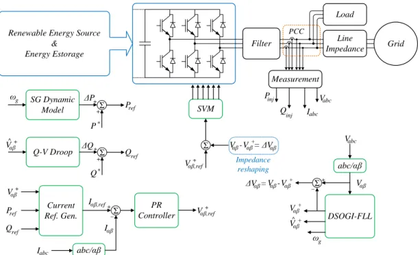
Figure 1 shows the layout of a three-phase interface converter connected to a power grid. The proposed interface converter control system includes several interconnected sub-systems working simultaneously to process voltages and currents in order to generate targeted references and provide supportive services. Under weak grid condition, unequal line impedances, unbalanced voltages, and harmonics are presumable, thus computing and extracting positive-sequence component of the PCC voltage is necessary. Accordingly, using a proper synchronization system can enhance converter performance positively. Phase-locked loop (PLL) is a commonly used grid synchronization technique for grid-connected converters whereas under weak grid condition, the coupling between PLL and grid impedance can result in converter instability and injecting harmonics to the grid. One of the main contributions of this paper is to suppress the influences of low-order harmonics of the PCC voltage caused by synchronization technique under weak grid condition, and modify the output impedance of the interface converter. DSOGI-FLL is a developed stationary reference frame synchronization system capable of computing fundamental-frequency positive- and negative-sequence components of the PCC voltage (as shown in Fig. 1) [8]. Besides, the DSOGI-FLL includes an FLL unit that estimates the grid frequency which is an integral part for
providing virtual inertia by emulating SG dynamics. Working in the αβ domain, just two SOGIs are necessary to compute the symmetrical components in a three-phase application, one for α, and another for β. SG dynamic model, Q-V droop control, current reference generator and controller, and feedforward technique are main parts of the proposed control system discussed in the following sections.
A. SG dynamic model
The SG dynamic model relating the frequency and active power as a function of inertia and damping effect, given as:
0
m el d T T J B dt where Tm and Tel are mechanical power and electrical torque, respectively, and ω is the SG rotor mechanical angular frequency. In addition, J and B are inertia and damping coefficient in the SG dynamic model, respectively. For further simplification, when implementing SG dynamics in the interface converter, it can be assumed that ω is equal to the angular frequency of the grid voltage (ωg) computed by the DSOGI-FLL and ω0 is the rated angular frequency of the power system. Hence, by considering desired value for the planned power P*, and required power for emulating SG dynamics Pref, active power reference can be calculated from:
* * 0 and ref m el g g g ref g g P P T T d P P P J B dt Renewable Energy Source & Energy Estorage PCC Load Vabc Iabc Q inj Pinj SVM Q* Q-V Droop ΔQ Σ V^αβ+ Qref + + P* SG Dynamic Model ωg ΔP Σ Pref + + Current Ref. Gen. Pref Qref Vαβ+ Iαβ,ref Σ abc/αβ Iabc Iαβ + _ PR Controller Vαβ,ref + Σ Vαβ,ref+ Vαβ+ V -αβ Impedance reshaping DSOGI-FLL Vabc Vαβ+ Vαβ+ V -αβ ωg V^αβ+ abc/αβ Vαβ Σ _ + ΔV =αβ = ΔVαβ Filter Line Impedance Grid Measurement
* 0 g ref g g d P P J B dt Since derivative is a non-causal operator, it can be replaced by the following transfer function in the Laplace domain as: d s s s
where ωd adds a delay to the derivative operation and makes it executable to apply inertial response based on grid angular frequency fluctuation. Then, ΔP and Pref can be found as:
0 * g g c c g s d ref s s s P J B s P P P Equation (4) is used in the SG dynamic model block in Fig. 1. By applying SG dynamic model and providing virtual inertia Jc and virtual damping Bc, the interface converter contributes to the grid stability enhancement.
B. Q-V droop control
The droop control for compensating positive-sequence voltage drop is applied in the block “Q-V Droop” shown in Fig. 1. This block computes ΔQ in order to regulate positive-sequence voltage amplitude at the PCC and present voltage supportive function under voltage drop condition by adding ΔQ to the planned reactive power Q*. The reactive power reference Qref is calculated as:
* ˆ ˆ
( rated )
ref v
Q Q k V V
where ˆVrated
is the rated value of the PCC voltage in αβ frame, ˆV is the amplitude of positive-sequence component of PCC voltage in αβ frame, and kv is the reactive power droop coefficient
C. Impedance reshaping
The output impedance of the interface converter is based on the converter output voltage and the filter impedance. Feedforwarding the non-fundamental PCC voltage component ΔV to the voltage reference of the converter (demonstrated in Fig. 1), shapes the output impedance of the converter. Fig. 2 demonstrates the impedance-based model of the proposed method. It is important to recognize that the converter voltage includes two constituents, first one is computed by the PR controller to inject desired current and the second one is the feedforward of non-fundamental PCC voltage component. In addition, the mean total time delay Td for sampling, computing, and switching is given by:
1.5
d s
T T
where Ts is the sampling period of the control system. Converter current can be written as (6):
1 d d d T s ref s PCC s conv s conv s filter s filter s T s T s ref s conv s filter s filter s V V V V e V V I Z Z V V e V e I Z Z Converter current Iconv(s) consists of two components, ΔI(s) is the undesired part of the current that the proposed control technique tries to cancel it by shaping the output impedance of the converter.
conv s conv s s
I I I
Converter impedance corresponding to the non-fundamental PCC voltage component can be calculated as:
1 1 1 1 d d s T s filter s z s T s V Z Z I e K e
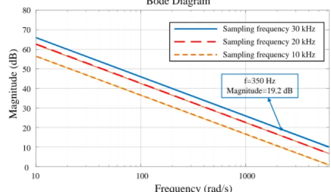
Bode diagram of impedance-shaping factor Kz(s) for three typical sampling frequencies is depicted in Fig. 3. Noting that the sampling frequency is normally twice the switching frequency in conventional power electronic converters, as shown in Fig. 3, magnitude of Kz(s) for the seventh-harmonic frequency (350 Hz) for sampling frequency of 30 kHz is equal to 19.2 dB, which means large increase in the converter impedance to the wide-ranging harmonics. Moreover, Kz(s) brings considerable impedance modification for grid-frequency unbalanced contents, which is generally present due to unequal grid impedances in three phases under weak grid condition.
Zfilter Zline Vgrid + _ + _ PCC ΔV e-T sd Vref+e-T sd + _ Zconv Iconv VPCC Vconv
Fig. 2. Equivalent circuit for computing converter output impedance.
Sampling frequency 30 kHz Sampling frequency 20 kHz Sampling frequency 10 kHz Bode Diagram 80 70 60 50 40 30 20 10 0 M ag n it u d e (d B ) 10 100 1000 Frequency (rad/s) f=350 Hz Magnitude=19.2 dB
D. Current reference generator and PR controller
As discussed earlier, the impedance shaping technique blocks non-fundamental current component injection to the grid, therefore, active and reactive power equations for positive-sequence fundamental current reference generation can be expressed as:
P V I V I Q V I V I
thus the current references can be computed as:
, 2 2 , 2 2 ref ref ref ref ref ref P V Q V I V V P V Q V I V V Then, the current references according to (10) are given to proportional resonant (PR) current controller. PR controller is defined by proportional constant KP and integral time constant KI as P I 2 2 c s g s G K K s
The PR controller has very high gain in a limited frequency band centred at the resonance frequency ωg. Width of the frequency band depends on the integral time constant KI, where low values for KI lead to very narrow bands while high values of KI broaden the frequency band. Therefore, the controller can be tuned according to the grid requirements. In weak grid applications where the grid frequency is allowed to vary around 1%, an appropriate KI value can be found by frequency analysis. In the following, the proposed control technique is simulated and verified in several scenarios.
III. CASE STUDIES
In this section, carried out simulations of the proposed system using MATLAB/Simulink are presented and provided for two case studies. First, the performance of the interface converter when the grid impedance is high and unequal in different phases is discussed. Then, virtual inertia provision under grid frequency drop condition with high penetration level of renewables is demonstrated. Parameters of the simulated system are provided in TABLE I.
A. High and unequal grid impedances
The system short-circuit ratio (SCR) represents the stiffness of the grid to which the interface converter is connected. Generally, a grid with an SCR below 2.5 is considered as weak. Conversely, a grid is defined strong if the SCR is greater than 20. The proposed modified control technique was studied by simulation. The simulation results are presented in Fig. 4 for three different values of SCR (10, 3, and 2) and unequal grid impedances in the three phases as summarized in TABLE I.
The system starts with 0.45 p.u. initial active power, then the active power reference changes to 0.95 p.u. at time t = 0.3 s, 15% inequality is considered for the grid impedance in three phases. As it is clear in Fig. 4, despite the fact that the converter current quality is degraded by decreasing the SCR value, the converter injects power to the grid steadily and the current quality is still acceptable and the converter stability is ensured for the given values of grid SCR.
B. Virtual inertia provision during grid frequency drop
When a power plant drops off or a large load connects to the grid, there is an immediate shortfall in energy, which causes the grid frequency start dropping. When frequency drops suddenly, the interface converter should release energy to support the grid. This is inertial response, with each unit providing a power increase for a typical large event.
For evaluating the performance of the proposed control technique for providing virtual inertia by the interface converter, a power system including a 2 MW synchronous generator and an interface converter with the rated power of 600 kVA was modelled in MATLAB/Simulink. In this simulation, penetration level of RES is 30%, as shown in Fig. 5 after connecting a large load to the grid, the grid frequency drops to near 49 Hz, which is a considerable frequency drop, and out of the admissible frequency range.
TABLE I. PARAMETERS OF THE SIMULATED MODEL
Parameter Value
Rated Power (Sbase) 600 kVA
Voltage (Vbase) 400 V
Grid Frequency (fg) 50 Hz
Switching frequency (fsw) 4450 Hz
Grid-side filter inductance (Lfilter,g) 0.02 p.u.
Converter-side filter inductance (Lfilter,c) 0.02 p.u.
Filter capacitance (Cf) 0.25 p.u.
Grid impednace (Zg) 1/SCR p.u.
Phase A grid impedance (ZgA) Zg
Phase B grid impedance (ZgB) 1.15Zg
Phase C grid impedance (ZgC) 0.85Zg
Fig. 4. Power reference step change and converter three-phase currents for different SCR values under unequal phase-impedance condition.
The planned active power for the RES interface converter was set to 100 kW. The simulation has carried out for two modes, in the first one, the interface converter does not provide any virtual inertia and injects just the planned power to the grid (as depicted in Fig. 6), whereas in the second mode, the interface converter provides virtual inertia for supporting the grid frequency. According to TABLE I, the interface converter rated power is 600 kVA, so the converter can provide the peak value of the power shown in Fig. 6 by using storages or other power resources available in the DC side of the interface converter. Fig. 7 shows the three-phase currents of the interface converter for the two aforementioned modes.
According to Fig. 4, 5, 6, and 7, it can be seen that the proposed control technique guarantees that the interface converter can provide supportive services to the grid under weak grid condition, and enhance the stability of the system.
IV. CONCLUSION
This paper has shown that to provide supportive services to a weak grid with high penetration level of RES, it is feasible to take advantage of simplified SG models and modified synchronization techniques. In fact, the main contribution of this paper lies in an impedance reshaping and virtual inertia emulation technique using voltage feedforward method and simplified swing equation, respectively. In the proposed control technique, the developed controller inherently alleviates the negative impact of weak grid operating condition on the stability of interface converters and provides virtual inertia to support the power grid. The proposed technique makes it practicable to achieve supportive services and grid-friendly interaction of the interface converters under weak grid condition.
REFERENCES
[1] M. Mehrasa, E. Pouresmaeil, A. Sepehr, B. Pournazarian, and J. P.S. Catalão, “Control of power electronics-based synchronous generator for the integration of renewable energies into the power grid,”
International Journal of Electrical Power & Energy Systems, vol.
111, pp. 300-314, 2019.
[2] M. Mehrasa, A. Sepehr, E. Pouresmaeil, J. Kyyrä, M. Marzband, and J. P. S. Catalão, “Angular Frequency Dynamic-Based Control
Technique of a Grid-Interfaced Converter Emulated by a Synchronous Generator,” in 2018 International Conference on Smart
Energy Systems and Technologies (SEST), Sevilla, 2018, pp. 1-5.
[3] M. Mehrasa, E. Pouresmaeil, A. Sepehr, B. Pournazarian, M. Marzband, and J. P.S. Catalão, “Control Technique for the Operation of Grid-Tied Converters with High Penetration of Renewable Energy Resources,” Electric Power Systems Research, vol. 166, pp 18-28, 2019.
[4] M. Cespedes, and J. Sun, “Adaptive Control of Grid-Connected Inverters Based on Online Grid Impedance Measurements,” IEEE
Transactions on Sustainable Energy, vol. 5, no. 2, pp. 516-523, April
2014.
[5] M. F. M. Arani, Y. A. I. Mohamed, and E. F. El-Saadany, “Analysis and Mitigation of the Impacts of Asymmetrical Virtual Inertia,” IEEE
Transactions on Power Systems, vol. 29, no. 6, pp. 2862-2874, Nov.
2014.
[6] M. Mehrasa, E. Pouresmaeil, B. Pournazarian, A.Sepehr, M. Marzband, and J. P.S. Catalão, “Synchronous Resonant Control Technique to Address Power Grid Instability Problems Due to High Renewables Penetration,” Energies, vol. 11, no.9, p. 2469, Sept. 2018.
Fig. 5. Grid frequency for two operating modes of lacking virtual
inertia and providing virtual Inertia. Fig. 6. Converter active power for two operating mode of lacking
virtual inertia and providing virtual inertia.
Fig. 7. Converter three phase currents for two operating mode of lacking virtual inertia and providing virtual inertia.
[7] M. Mehrasa, A. Sepehr, E. Pouresmaeil, M. Marzband, J. P. S. Catalão, and J. Kyyrä, “Stability Analysis of a Synchronous Generator-Based Control Technique used in Large-Scale Grid Integration of Renewable Energy,” in 2018 International Conference
on Smart Energy Systems and Technologies (SEST), Sevilla, 2018, pp.
1-5.
[8] J. Matas, M. Castilla, J. Miret, L. García de Vicuña, and R. Guzman, “An Adaptive Prefiltering Method to Improve the Speed/Accuracy Tradeoff of Voltage Sequence Detection Methods Under Adverse Grid Conditions,” IEEE Transactions on Industrial Electronics, vol. 61, no. 5, pp. 2139-2151, May 2014.
[9] J. A. Suul, S. D'Arco, P. Rodríguez, and M. Molinas, “Impedance-compensated grid synchronisation for extending the stability range of weak grids with voltage source converters,” IET Generation,
Transmission & Distribution, vol. 10, no. 6, pp. 1315-1326, 21 4
2016.
[10] X. Chen, Y. Zhang, S. Wang, J. Chen, and C. Gong, “Impedance-Phased Dynamic Control Method for Grid-Connected Inverters in a Weak Grid,” IEEE Transactions on Power Electronics, vol. 32, no. 1, pp. 274-283, Jan. 2017.