Multiple Source DC Converter Topology for
Energy Diversification by using Pi and Smc
Prabha.V PG Student
Department of Electrical and Electronics Engineering SXCCE, Nagercoil, Tamilnadu, India
S V Kayalvizhi M.E, Phd Asst.Professor, SXCCE
Nagercoil,Tamil Nadu
Abstract- In DC to DC converter power conversion is usually achieved by appropriate configuration of the circuit components and proper operation of the semiconductor switches. In this paper A multiple source dc dc converter topology for energy diversification is proposed. the proposed converter is proficient for energy diversification from storage energy source and renewable energy sources individually or simultaneously. It has the capability to operate either in buck, boost or buck–boost mode of operation with possibility of bidirectional powerflow.to make the output constant PI and SMC controller are used. The proposed concept has been investigated through detailed device level simulation using MATLAB/Simulink environment .
Key word: multiple source dc dc converter ,PVSC,PCSC,HES,PI,SMC
I.INTRODUCTION
The use of renewable energy sources and the development of power electronics systems for capitalizing such energy sources have received renewed interest in the past decade. Common forms of renewable energy sources hydro energy, and wind energy, and many of such sources are mutually complementary in the sense that they can be utilized simultaneously to maintain continuous delivery of power to the load. However, the use of a number of single-input converters leads to relatively complex configuration and high cost. Recently, MSC finds potential application in the field of distributed generation, grid integrated PV/Wind hybrid generation system, electric vehicular technology, micro grid based power supply system etc.
In order to supply power simultaneously, input sources are connected in series[6,7,8]. In series configuration, each source can bypass other to form parallel connection through individual diode which increases reliability. In some topologies where sources are connected in parallel, power coupling effect can be well addressed by introducing transformer with multiple primary windings[8]. The concept of pulsating source cell (PSC)and their connection rules have been introduced in [9]. to over come this problem. several MSCs were derived by using these PSCs. The presented converter is proficient for energy diversification from different series connected energy sources and offers flexibility in source voltage magnitudes. Moreover, all the connected
energy sources can supply the load
individually or simultaneously. Possibilities of bidirectional power flow with buck, buck-boost
and boost modes of operation have been explored. The circuit may consist of nonlinearity like
delay, hysteresis etc. and because of this output voltage is not constant. To settle
the output voltage within minimum settling time and less overshoot different types of controllers are considered such as linear controller PI and nonlinear controllers SMC (sliding mode controller).II. MULTI-INPUT CONVERTER
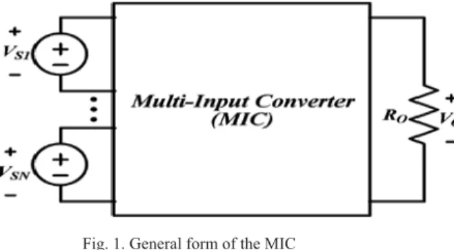
operate as does a PWM converter. On the other hand, when more than one input sources are supplied to the MIC, all these input sources will deliver power to the load simultaneously without disturbing each other’s operation. Moreover, no power is transferred from one of the input sources to another. Such an MIC can continue to operate even if one of the dc sources has failed.
Fig. 1. General form of the MIC
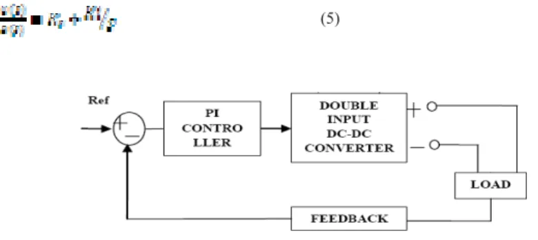
III.BLOCK DIAGRAM OF PROPOSED SYSTEM
Figure2. shows the block diagram of proposed converter Multiple single sources DC/DC converters can be successfully replaced by a single multiple source DC/DC converter. It offers simple and more compact design and reduces the cost and complexity of the system. In addition, efficient dc power distribution and higher degree of reliability can be achieved.
Figure.2.Block diagram of proposed converter
A. Operation :
The fundamental operation of such converter is to charge the passive elements during particular period of time and then discharge the stored energy of passive element through load during remaining period of time over a single switching cycle. In MSC, inductor can be charged by multiple voltage sources instead of single source by adopting appropriate switching pattern that connects or disconnects multiple sources to inductor individually or simultaneously. For detailed analysis and simplicity of the proposed MSC, two PVSC connected in series are taken along with converter cell and load (a two input DC/DC converter) as shown in Fig.3. The architecture of two input DC/DC converter with PVSC-1 and PVSC-2 are represented by their corresponding voltage sources V1 and V2, switch T1 and T2 and diode D1 and D2 respectively . Basically conduction of switch T1 and T2 decides the working state and the source in operation, whereas conduction of switch T3 and T4 decides the operating mode (buck, boost and bidirectional operation).
Figure.3.Conceptual circuit diagram of proposed MSC for two input source
The proposed converter can operate in buck, buck–boost and boost mode of operation.
Buck–boost mode : In this mode, switch T3 is controlled such that it conducts simultaneously with T1, T2 or both. In other words switching signal of switch T3 is a function of switching signal of switch T1 and T2 [d3 = max(d1 OR d2)]. In this case the duty ratio of switch T3 (T1 and/or T2) remains less than unity always. Switching function of T1 and T2 determines the power drawn from the source whereas duty ratio of switch T3 decides buck or boost mode of operation. Boost mode : In this mode, either voltage level of individual or combination of input sources can be boosted. The boosting level is decided by the charging of inductor L through switch T3. Inductor can be charged with voltages V1 or V2 or V1 + V2 over a predefined conduction time of switch T3.
B. proposed converter analysis:
In this proposed converter rising edge synchronization of gate pulses have been taken for the analysis of the proposed converter.
Fig.4 . rising edge synchronization
In steady state using volt-second balance equation, the average inductor voltage should be zero. Therefore, Average inductor voltage = (1)
From Fig4.Eq. (1) can be written as,
Simplifying the Eq. (3.2) we get input–output voltage relationship as,
. For lossless system, input output power relationship can be given as;
+ = (4)
C. Necessity for controlling of dc to dc converters:
Any DC to DC converter will be designed for specific input voltage and output conditions. In other words, the circuit will be operated at steady state condition only. But in practice this may not be possible and there is always a possibility of some disturbances. A control technique suitable for DC-DC converters must cope with their intrinsic nonlinearity and wide input voltage and load variations, ensuring stability in any operating condition while providing fast transient response. Various control techniques are there: Fuzzy logic controller, Artificial Neural Network (ANN), PID controller, PI controller, sliding mode controller. From these control methods PI, and SMC are used in the proposed paper.
PI-controller:
The integral term in a PI controller causes the steady-state error to reduce to zero, which is not the case for
proportional-only control in general. The lack of derivative action may make the system more steady in the steady
state in the case of noisy data.
(5)
Figure 5.Block diagram of converter with PI controller
SLIDING MODE CONTROLLER:
SMC is a robust control strategy and it has very simple procedure to design the controllers for linear and nonlinear plants. The main advantage of SMC is that, it is robust to plant uncertainties and insensitive to disturbances acting on the system. Because of its excellent robustness to uncertainties, robust control of uncertain systems. Different types of SMC are following:
(i) Conventional sliding mode control. (ii) Global sliding mode control. (iii) Fuzzy sliding mode control.
The transient process of conventional SMC consists of two phases: reaching phase and sliding phase. The key idea of GSMC is to eliminate the reaching phase. In this case, the transient process of the conventional SMC system is totally within the sliding phase, and the global robustness is therefore guaranteed.
For the Buck converter we consider the following sliding surface S :
(6)
(7)
(8)
Let us consider the positive definite Lyapunov function Vdefined as follow
(9)
The time derivative of Vmust be negative definite < 0 to insure the stability of the system and to make the
surface S attractive. Such condition leads to the following inequality.
Advantages and Drawbacks:
Control does not require linearization. It is based on principal behavior, which makes it insensitive to parameter
variations. Decisions are based on current system state, no memory required. Mathematical analysis can be difficult
.
IV. SIMULTION AND RESULT
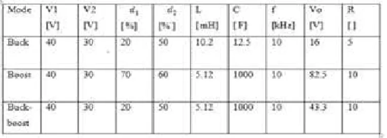
Simulation studies for two series-connected input sources are performed for Buck, Boost, and buck-boost modes of operation. Simulation parameters are given in table 1for both the modes of operation. The switches are IGBT/Diode with constant switching frequency of 10 kHz.
Table:1 simulation parameter for MIC
4.1 SIMULINK MODEL OF TWO INPUT SOURCE CONVERTER FOR BUCK MODE OF OPERATION
Figure 6.two input source converter for buck mode with PI
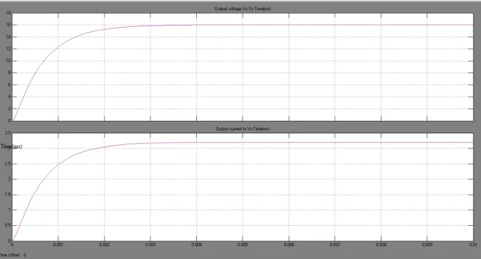
Figure .7.Different waveforms for buck mode of operation output current ,and output voltage for v1=30 v; v2=20 v,d1=0.2 , d2=0.5 .
Figure .9.Different waveforms for buck mode of operation with SMC output current and output voltage for v1=30 v; v2=20 v,d1=0.2 , d2=0.5 . Table.2.comparison of output
Settling Time(ms)
Buck Boost Buck-Boost
PI
0.009
0.0065
0.08
SMC
0.003 0.003 0.015
IV.CONCLUSION
REFERENCES
[1] Nanda R Mude, Prof. Ashish Sahu Adaptive Control Schemes For DC- DC Buck Converter
[2] Serdar Ethem Hamamci* Nusret Tan, Design of PI controllers for achieving time and frequency domain specifications simultaneously.
[3] Jiang Wei,Fahimi B.Multiport power electronic interface concept,modeling,and design. IEEE Trans power Electron 2011;26(7):1890–900.=5
[4] Khaligh A,Jian Cao,Young-Joo Lee. Amultiple-input DC–Dc converter topology. IEEE Trans Power Electron 2009;24(3):862–8.
[5] Gummi K,Ferdowsi M.Double-input DC–DC power electronic converters for electric-drive vehicles—topology exploration and synthesis using a single-pole triple-throw switch. IEEE Trans Industr Electron 2010;57(2):617–23.
[6] Chen Yaow-Ming,Liu Yuan-Chuan,Lin Sheng-Hsien. Double-input PWM DC/DC converter for high-/low-voltage sources. IEEE Trans Industr Electron 2006;53(5):1538–45.
[7] Ahmadi R,Ferdowsi M.Double-input converters based on h-bridge cells: derivation, small-signal modeling,and power sharing analysis.IEEE Trans Circuit Syst 2012;59(4):875–88.
[8] Kumar L,Jain S. Anovel multiple input DC–DC converter for electric vehicular applications. In:Transportation electrification conference and Expo (ITEC), IEEE 18–20 June 2012.p.1–6.