A Prospective Geoinformatic Approach to
Indoor Navigation for Unmanned Air
System (UAS) by use of Quick Response
(QR) codes
A Prospective Geoinformatics Approach to Indoor Navigation for
Unmanned Air System (UAS) by use of Quick Response (QR) codes
By
Emilio Troncho Jordán
Dissertation supervised by Ignacio Guerrero, Ph.D
Institute of New Imaging Technologies (INIT), Universitat Jaume I, Castellón, Spain
Cosupervised by Torsten Prinz, Ph.D
Westfälische Wilhelms-Universität (WWU), Münster, Germany
and
Roberto Henriques, Ph.D
NOVA Information Management School (NOVA IMS), Universidade Nova de Lisboa, Lisbon, Portugal.
ACKNOWLEDGMENTS
I would like to thank Professor Dr. Ignacio Guerrero, for being my supervisor, for all the help he provided and for showing me the remote sensing world. Besides, I would like to thank my Co-supervisors, Professor Dr. Torsten Prinz, for all the help and for providing me with the first introduction in the UAS world and Professor Dr. Roberto Henriques for his contribution.
Thanks also to all my student partners, a special mention to Andrea for their support, help and friendship, it’s been a pleasure to share this journey with them and to help each other.
Special thanks to my parents, family and friends for making this possible.
A Prospective Geoinformatics Approach to Indoor Navigation for
Unmanned Air System (UAS) by use of Quick Response (QR) codes
ABSTRACT
A Prospective Geoinformatics Approach to Indoor Navigation for
Unmanned Air System (UAS) by use of Quick Response (QR) codes
ABSTRACT (Spanish)
KEYWORDS
Unmanned Aircraft System Indoor Navigation
QR codes
Inertial Navigation System
KEYWORDS (Spanish)
Sistema Aéreo No Tripulado
Navegación en Interior de Edificaciones Códigos QR
ACRONYMS
AESA – Agencia Estatal de Seguridad Aérea API – Application Programming Interface AoA – Angle of arrival
EASA – European Aviation Safety Agency GIS – Geographical Information Systems GNSS – Global Navigation Satellite Systems GPS – Global Positioning System
ICAO – International Civil Aviation Organization IGS – Inertial Guidance System
INS – Inertial Navigation System IMU – Inertial Measurement Unit IR – Infrared
LIDAR – Laser Imaging Detection and Ranging LoS – Line of Sight
QR – Quick Response RF – Radio Frequency
RPAS – Remotely Piloted Aircraft Systems RSS – Received Strength Signals
RSSI – Received Signal Strength Indicator SAR – Search and Rescue
SOP – Signals of opportunity SDK – Software Development Kit TDoA – Time Difference of Arrival ToF – Time of Flight
UAV – Unmanned Aerial Vehicle UAS – Unmanned Air System US – Ultrasound
INDEX OF THE TEXT
Pag.
ACKNOWLEDGMENTS ... ii
ABSTRACT ... iii
ABSTRACT ... iv
KEYWORDS ... v
KEYWORDS ... v
ACRONYMS ... vi
INDEX OF TABLES ... ix
INDEX OF FIGURES ... x
1. INTRODUCTION ... 1
1.1 Introduction ... 1
1.2 Motivation ... 4
1.3 Aims and Objective ... 6
1.4 Challenges ... 7
1.5 Regulations ... 7
2. OVERVIEW ... 8
2.1 Indoor Navigation ... 8
2.2 Indoor Localization Techniques ... 8
2.2.1 Technologies Based on Signals of Opportunity (SOP) ... 8
2.2.1.1 Wi-Fi and Bluetooth ... 8
2.2.2 Technologies Based on Pre-deployed Infrastructure ... 9
2.2.2.1 Radio Frequency Identification (RFID) ... 9
2.2.2.2 Ultrasound ... 10
2.2.2.3 Infrared (IR) ... 10
2.2.2.4 Ultra-wideband Radio (UWB) ... 11
2.2.3 Others Technologies ... 11
2.2.3.1 Inertial Navigation System (INS) ... 11
2.3 Preliminary Theory ... 12
2.3.1 Inertial Sensors and Heading ... 12
2.3.1.1 Electronic Compass ... 13
2.3.1.2 Accelerometer………... ... 14
2.3.1.3 Gyroscope………... ... 15
2.3.1.4 Inertial Measurement Unit (IMU)………... ... 17
2.3.2 Quick Response (QR) Code………... ... 18
3. AR.DRONE 2.0……… ... 24
3.1 Hardware AR.Drone 2.0 ... 26
3.1.1 Electronic Features……… ... 26
3.1.2 HD Video Recording……… ... 26
3.1.3 Structure……… ... 27
3.1.4 Motor………. ... 27
3.2 Software AR.Drone 2.0 ... 28
3.2.1 Architecture……….. ... 28
3.2.2 SDK 2.0.1……….. ... 29
4. INDOOR NAVIGATION SYSTEM IMPLEMENTATION………. ... 31
4.1 Onboard Hardware ... 31
4.1.1 Raspberry Pi Zero ... 31
4.2 Software Prerequisites ... 32
4.2.1 Linux……….. ... 32
4.2.2 Node.js……… ... 32
4.2.3 Node ar-drone………. ... 33
4.2.4 Cairo……… ... 33
4.2.5 FFmpeg……….. ... 33
4.2.6 Qrar……….. ... 33
4.3 Drone-browser……… ... 34
4.4 Codigo-Qr.es……… ... 34
4.5 Main application……… ... 35
4.5.1 Streaming Video ... 36
4.5.2 Navigation data ... 37
4.5.3 Node-ar-drone-pilot ... 39
4.5.4 Drone-pilot.js ... 40
5. TESTING AND RESULTS……….. ... 43
5.1 Communication AR.Drone 2.0-Client ……… ... 43
5.2 Running the Application node-ar-drone-pilot ……….. ... 44
5.3 Results……….. ... 45
6. CONCLUSIONS AND FUTURE WORK……… ... 48
6.1 Conclusions……….. ... 48
6.2 Future Work……… ... 49
BIBLIOGRAPHIC REFERENCES…... 51
ATTACHMENTS... ... 56
A1. Navdata……… ... 56
INDEX OF TABLES
INDEX OF FIGURES
Figure 1: The Apollo spaceship (IMU) for navigation guidance and control to carry men to the Moon and back, that contains three gimbals, platform electronics,
accelerometers and gyros [2] ... 2
Figure 2: Parrot AR.Drone2.0 used for developing this project [38]……… ... 4
Figure 3: Global Hawk, NASA's unmanned aircraft system for high-altitude, long-duration Earth science missions [5]……… ... 5
Figure 4: National and international aviation safety agencies, Agencia Estatal de Seguridad Aérea (AESA, Spain), European Aviation Safety Agency (EASA, Europe), European Organization for the Safety of Air Navigation (Eurocontrol, Europe) and International Civil Aviation Organization (ICAO, worldwide), agencies that regulate the activities of UAS [54][55][56][57] ... 7
Figure 5: 3-Axis Digital Compass HMC5883L used in AR.Drone 2.0 [43]…… ... 13
Figure 6: Basic components of a mechanical accelerometer [30]………. ... 14
Figure 7: MEMS accelerometer. Given its small size it is possible to integrate into many electronic devices [32]……… ... 15
Figure 8: Basic diagram of the mechanical gyroscope. A mechanical device used to measure, maintain or change the orientation in space [30]… ... 16
Figure 9: MEMS gyroscope from STMicroelectronics. Given its small size it is possible to integrate into many electronic devices [32]……… ... 17
Figure 10: IMU blocks diagram. Electronic device that measures and reports speed, orientation and gravitational forces of a device, using a combination of accelerometers and gyroscopes [31]……… ... 17
Figure 11: QR code - takeoff (). Takeoff instructions encoded in QR code with codigo-qr [51]……… ... 18
Figure 12: Three-dimensional reference system. A coordinate system is a set of Values and points that allow uniquely define the position of any point in space [37]……… ... 19
Figure 13: Pitch, roll and yaw axis definition for an airplane [37]……… ... 20
Figure 14: Cross structure of a quadcopter [38]……… ... 20
Figure 15: Four rotors with the same power for climbing [38] ... 21
Figure 16: Roll movement [38]……… ... 21
Figure 18: Yaw movement [38] ... 22
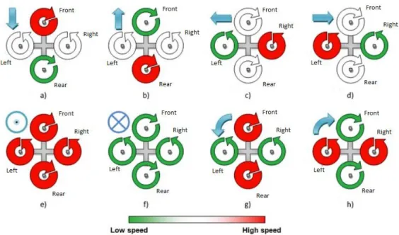
Figure 19: Behavior of the quadcopters rotors for different movements, a) backward, b) forward, c) left roll, d) right roll, e) up, f) down, g) left yaw, h) right yaw [38]. ... 23
Figure 20: AR.Drone 2.0 (top and bottom view with indoor cover) [3]……… ... 24
Figure 21: Pitch and roll movements [3]… ... 24
Figure 22: Rotation movement about its vertical axis [3] ... 24
Figure 23: Elevation and descending movements [3] ... 25
Figure 24: Electronic specifications and position in the structure of the AR.Drone 2.0 [43]……… ... 28
Figure 25: Here is an overview of the layered architecture of a host application built upon the AR.Drone 2.0 SDK [41]……… ... 29
Figure 26: Raspberry Pi Zero. Its size is ideal for this project because it can be installed inside the hull of the AR.Drone 2.0 [52]……… ... 31
Figure 27: Software versions in Raspberry Pi……… ... 32
Figure 28: Ubuntu version installed in laptop ... 32
Figure 29: Node.js version installed ... 32
Figure 30: Installing ar-drone... ... 33
Figure 31: Installing Cairo library ... 33
Figure 32: Installing FFmpeg. ... 33
Figure 33: Manual control application execution for controlling AR.Drone 2.0 ... 34
Figure 34: Manual control for AR.Drone 2.0. In case of problems with the autonomous flight application, we will take the control of the AR.Drone 2.0 by this application……… ... 34
Figure 35: Dialog box of Codigo-QR. Application to generate QR codes with the information that we insert it [51]……… ... 34
Figure 36: Result of the instruction takeoff () in a QR code using Codigo-qr [51] ... 35
Figure 37: Diagram of the architecture of the autonomous navigation system. ... 36
Figure 39: Communication Client-AR.Drone 2.0. Ports for exchanging information
between client-AR.Drone 2.0, in this case, video stream and navdata……… ... 37
Figure 40: Request of navdata between the client and AR.Drone 2.0 [38]……… ... 38
Figure 41: node-ar-drone-pilot file structure with dependencies on ar-drone and qrar libraries. Application files structure………. ... 39
Figure 42: node-ar-drone-pilot file structure with data obtained on the flight. In the folder log we have the nav data and magneto data, in the video folder, we found the video file recorded. Data files structure……… ... 40
Figure 43: node-ar-drone-pilot structure. Processed information flow between different parts of the application and AR.Drone 2.0.……… ... 42
Figure 44: A visual representation of the project execution carried out in a garage of the University Jaime I of Castellón……… ... 43
Figure 45: The Wi-Fi connection between client-AR.Drone 2.0……… ... 43
Figure 46: Sequence diagram of the application node-ar-drone-pilot……… ... 44
Figure 47: drone-pilot.js execution ……… ... 45
Figure 48: Sequence of instructions to initialize the system. Takeoff, compass calibration and change configuration to the bottom camera……… ... 45
Figure 49: Sequence of instructions to turn on the right 90º and continue straight... ... 45
Figure 50: Sequence of instructions for landing ... 45
1. INTRODUCTION
1.1 Introduction
In the era of new technology advances at a frantic pace, the world of aviation has not been left behind. Airplanes have evolved into one of the means of transport and become safer. Besides airplanes, different aerial vehicles used have appeared, transport and leisure. Namely, aerial vehicles have gone from having only the function of transporting people or goods to being remote control toys used by children, creating a market that has expanded worldwide creating companies dedicated exclusively to it.
Since 1903, the Wright brothers managed to fly a few meters with a motor-propelled aircraft, the changes undergone by the world aviation have been very large. Improvements have been happening and have managed to create lighter and stronger aircraft, very different from the first wooden aircraft materials.
Early pilots who crossed the skies flying, used the first techniques and technologies for air navigation to be able to guide the plane to the destination, they used observation, speed, heading and time to estimate their position. To know the position in the airspace of the plane, attitude, pilots watched the horizon be sure they were flying in the right position relative to the ground. At that time, the pilots only had their view, a map, a compass and a watch for navigating.
In the 1920s, new equipment was introduced in the cockpit, to help pilots in their flights, bubble of liquid to keep wings level, a barometer to measure heights of flight, called altimeter, which told the pilot his altitude above ground. A compass to indicate to the pilot the actual course. The first navigation aids were the aerial beacon, acetylene lamps built.
In 1929, Lawrence Sperry introduced the artificial horizon that works on gyroscope principles. Artificial horizon shows the orientation of the aircraft relative to the horizon. With it is possible to know the angle of pitch and roll relative to the ground [1].
Figure 1: The Apollo spaceship (IMU) for navigation guidance and control to carry men to the Moon and back, that contains three gimbals, platform electronics, accelerometers and gyros [2].
Nowadays global positioning systems have changed our professional activity in many sectors, as well as our daily lives. GNSS (Global Navigation Satellite System) have reached such importance today, that the most important nations have or are in the process of having its own satellite constellations (see GPS, GLONASS, Galileo and Compass) to serve all.
While outdoor GNSS systems are the undisputed solution for positioning, urban, hilly, and wooded and most notably in areas inside buildings signal availability is very low, so the systems do not apply in these contexts. It has been established therefore looking for a system equivalent to GNSS positioning capabilities to operate within an indoor building. Today, neither the market research in universities offers an "Indoor GPS" to be imposed clearly. Shaping the inside of a building in terms of propagation of a signal is not at all easy, but it is not an obstacle to good approximations is published with increasing frequency.
Large technology companies are now interested in the indoor location. They are seeking to have a compact solution that can be integrated into their mobile devices, taking advantage of its computing power and new sensory capabilities of these devices. There are many applications for mapping and navigation based vision systems.
In the field of mobile robotics, the problem of indoor location and navigation solutions has long been sought. Industrial robots perform those activities almost exclusively inside buildings as well as warehouses, factories, hospitals, etc. These robots are increasingly better equipped in terms of sensory capacity, energy independence, and computing power. The ability to achieve the objectives and make decisions to overcome unforeseen situations is the next step forward for mobile robots on their way to autonomy.
performed, the UAS can vary in structure; hardware and software they use, for instance the UAS can be differentiated basis with fixed or rotary wing structure. UAS have a set of sensors that allow them to capture information about the current flight and the environment. The use of UAS indoor for industrial applications is growing and many companies are interested in its use and develop.
The emergences of new technologies are contributing to new remote navigation and autonomous system. This project will discuss and use an autonomous indoor navigation system for UAS through inertial systems and landmarks. UAS has become fashionable in recent years because of its military use. Such is the population expansion that governments have had to enact laws to regulate their use. For example, in Spain, the Agencia Estatal de Seguridad Aérea (AESA) is responsible for controlling the use of remote-controlled aircraft.
There are small differences between the UASs used for research and development and those used for recreation, as some of these models for this purpose are usually "modified" to some extent, either in hardware and software level. In the market, we will find many of these models in specialized websites or on the websites of the same companies that make them. One of the highlights is the AR.Drone.
It is no coincidence that the most used is the AR.Drone, as it is one of the most popular and which also will be used in this project. Full description and main characteristics are detailed below, but we can say that is a civilian quadcopter for recreational use which is controlled by a mobile device or via a computer [3]. It is currently in version 2.0 (July 2012) and applications can be developed with a software development kit (SDK) that can be downloaded freely in a platform for this purpose [4].
The reasons why we have opted for the AR.Drone 2.0 model and not another UAS are several.
First, his growing fame has made many people interested in it, so we can say that there is plenty of information and documentation on the network.
Secondly, the fact that is supported by mobile devices and the operating system, which makes the SDK, is very functional and adaptable.
Likewise, the fact that there is a development-oriented application for the AR.Drone platform is a point in its favour.
We can also say that among the characteristics of the AR.Drone, we would highlight a couple of cameras through which we can see the flight. This makes it ideal for certain applications.
Figure 2: Parrot AR.Drone 2.0 used for developing this project [38].
In short, the SDK is a strong point on which to rely as our choice argument. There are too many commercial drones that have a method of developing applications, as for more sophisticated we have to migrate to platforms such as Arduino microcontroller or concrete projects of some universities [5].
1.2 Motivation
The motivation for this project stem from an interest in a technology that becomes more popular, UAS (Unmanned Aircraft System), UAV (Unmanned Aerial Vehicle) or RPAS (Remotely Piloted Aircraft Systems) it is a flying platform that can fly with different kinds of sensors (cameras, IR cameras, Lidar, etc...) and without human pilot on-board. Today with the advances of new technologies, UAS have become an indispensable tool for certain purposes in any field of human activity. Either to inspect a dangerous ground or to facilitate the task of observing remote areas, its use is extensive. These systems can take a lot of information for different uses:
Search and Rescue (SAR): Search and locate people and animals in natural disasters, accidents or any emergency
Agriculture: Control of agricultural subsidies, detection of nutritional stress in crops, detection of water stress on crops for efficient water management, early detection of diseases and pests in crops, quality indexes of crops, Inventorying crop areas, fumigation, etc.
Inspections: Inspections of wind turbines, power lines, train tracks, pipelines, roads, etc.
Surveillance/Security: Coordinate security operations, sports events, floods, public events, traffic sensing, etc.
Science and Research: Forest monitoring, wealth management, observe a volcanic eruption or document an archeological excavation, ocean and coast research.
Surveying/GIS: Frequent updating of map databases and cadastral, topography, photogrammetry, remote sensing, etc.
Transport Payloads: Transport small goods in nearby areas
Environment: Endangered species, forest fires, contaminant spill, pollution, forest monitoring, watersheds, environmental impact and control areas, etc.
Figure 3: Global Hawk, NASA's unmanned aircraft system for high-altitude, long-duration Earth science missions [5].
Although an UAS has many advantages for certain tasks, and they are very safe in flight as they are controlled if an UAS fails to receive external control signals, having a large mass uncontrolled flying without control it can become very dangerous. This makes conducting research on an autonomous UAS very challenging. For terrestrial mobile robots or robotic manipulators, basic visual control servo series is a well-studied problem with a series of solutions provided, but robots are still many challenges to fly. The problem is greater because flying UAS operating in 3D-space as opposed to 2D surface ground robots navigate.
Indoor navigation for UAS is an interesting area for research because there are some people, institutions and companies researching in this field. There are different ways to create an indoor navigation system. In this project we develop an indoor navigation based on the Inertial Navigation System and landmarks, using Quick Response (QR) codes as landmarks.
1.3 Aims and Objectives
The aim of the project is to research in autonomous indoor navigation method through QR codes and with the use of UAS, in this case, an AR.Drone 2.0 of Parrot Company. The point is that the UAS could navigate and do different operations through the indoor navigation system.
1. Research into current autonomous navigation with INS and QR codes. 2. Research into algorithms for QR codes system.
3. Identify the best method for autonomous task based on indoor
navigation through INS and QR codes.
4. Design a prototype for AR.Drone using different sensors and parts. 5. Develop and code the algorithms for indoor navigation through QR
codes.
6. Acquire conclusions of the system solution and trying to improve. 7. Develop ideas to implement in the future.
The work presented in this project has been developed following different sources where we can use to gather important data. These sources of information come from many places, previous research, open source information and technical documentation from manufacturers.
For this research we will use the AR.Drone, It will be important to know and understand his navigation and control technology [3] [6] as well as the tracking algorithms to autonomously following dynamic targets at low altitude [7] to develop the base of this project. The AR.Drone 2.0 is a quadcopter built by the French company Parrot. The equipment on-board AR.Drone 2.0 It is composed by two cameras (front HD. 720 p 30 FPS, below QVGA de 60 FPS). Ultrasonic sensors to measure the altitude of progress, allowing for more stable flight and hovering. 1GHz processor and 32-bit ARM Cortex A8, and Wi-Fi b g n. 3-axis gyro with an accuracy of 2000°/sec, 3-axis accelerometer with an accuracy of +/-50mg, 3-axis magnetometer to within 6 °. One USB 2.0 and RAM 1GB DDR2 200 MHz among others.
We use QR codes and the INS like a new technique for autonomous navigation for UAS on indoor building in closed-loop, where we cannot use GPS system. This system is useful for outdoor, but in this research, we only test it in indoor.
1.4 Challenges
The indoor navigation system must overcome numerous hardware and software design challenges including:
Positioning accuracy: The position of the UAS will have a range of error due to the mistakes of the sensor noise, bias and scale factor errors that cause a significant increase in the position estimation errors [10]. The use of low-cost sensors increases these errors, in addition, to greater area overflown the error increases. In this case, small areas will fly to perform tasks in a closed loop. The use of QR codes helps us improve accuracy as it can include different information in them, such as their position.
Power and computational constraints: Due to computational limitations and flight autonomy (battery) in AR.Drone [3], the system designed for this application must be developed within these limitations.
Application develops and security: The system must know the needs of application development as well as system security of people and property with which to engage. The system must prepare a manual control system whereby if the system is compromised the user controls the system manually. Scalability: The system should be able to allow scalability, allowing
adaptations to incorporate the system for improvement. Proximity sensors for improved safety, embedded systems, laser sensors, electromechanical systems, Laser Imaging Detection and Ranging (LIDAR), artificial vision software etc. to increase the accuracy, capacity and safety of navigation.
1.5 Regulations
In Spain, the Agencia Estatal de Seguridad Aérea (AESA) is responsible for controlling the use of remote-controlled aircraft. This entity has issued the flight of UASs is not allowed in public spaces with commercial or professional purposes, and that if a user wants to use them for any purpose other than recreation or sports, it is necessary to have to request authorization from AESA. As for indoor using these aircraft is not regulated, so may be used under the responsibility of the pilot [54][55][56][57].
Figure 4: National and international aviation safety agencies, Agencia Estatal de Seguridad Aérea (AESA, Spain), European Aviation Safety Agency (EASA, Europe), European Organization for the Safety of Air Navigation (Eurocontrol, Europe) and International Civil Aviation Organization (ICAO,
2. OVERVIEW
2.1 Indoor Navigation
In the past, we have seen the evolution of Global Navigation Satellite Systems (GNSS), GPS is an example of this evolution. Navigation in outdoor environments is a mature technology nowadays, but there are several problems like it is no possible to receive good quality satellite signals, somebody could be jamming the signals or inside most buildings it is no possible receive signals. Many technologies are solving these problems.
The indoor localization technologies can be classified into three categories [11]: Technologies based on signals of opportunity (SOP).
Technologies based on pre-deployed infrastructure. Others technologies.
For a complete satisfactory navigation by mobile autonomous robots, it is required complete the next four steps:
Perception, capacity to extract data from the environment by different sensors. Localization, process for determining the position in space.
Cognition, make decisions to achieve goals.
Motion control, the control system commands to manage actuators for moving in the right direction to the next position.
2.2 Indoor Localization Techniques
2.2.1 Technologies Based on Signals of Opportunity (SOP)
The signals of opportunity normally are electro-magnetic signals, such Wi-Fi, TV, radio, cell-phone etc. The main advantages are the low cost and wide coverage. These signals are designed for other purposes but we can use them for positioning [12] [13] [14] [15].
2.2.1.1 Wi-Fi and Bluetooth
the source, calculating the attenuation suffered can calculate the distance to the emittor. This technique uses the attenuation of the received signal to locate the mobile device, and can estimate the distance between the mobile terminal of each access point, but the relative distance-power of the received signal is not very clear, having multipath, reflections, diffractions etc. One advantage of this technique is that no synchronization is required for the distance measurement, it is easy to implement and inexpensive. One of its major drawbacks is the variability of the signal which causes multipath and interference. The accuracy is between 1-3m [16][17].
There are two techniques used by the RSS. The first one is triangulation, which involves determining the position of an object based on triangulation which is the intersection of at least three circles centred on each known position (in this case, stations or access points) fixed, the radius must be related to the parameter measured (in this case, received power). The accuracy of triangulation depends on the precision of each of the measurements. The measurements may be distorted due to the orientation of the antennas, multipath, attenuation by the presence of obstacles. The second one is fingerprinting based on comparing the position data stored in databases previously with the user position in the real time; they can be used both unilateral and multilateral.
2.2.2 Technologies Based on Pre-deployed Infrastructure
Depending on the needs is possible to install certain infrastructures employed to carry a positioning system. Many technologies based on pre-deployed infrastructure based on ultrasounds, infrared, ultra-wide band, etc. is expensive and the coverage is limited but on the other hand, they have higher location accuracy [18] [19] [20] [21].
2.2.2.1 Radio Frequency Identification
(RFID)
Radio frequency identification (RFID) it is a means of storing and transmitting data via electromagnetic waves supports an integrated circuit RF. An RFID system comprises mainly: RFID Readers, RFID (active or passive) tags, and communication between them. Readers read the information issued by the tags, both using an RF protocol defined.
2.2.2.2 Ultrasound
Ultrasounds are not perceptible acoustic waves by humans, namely any frequency above 20 kHz, values between 1 and 20 MHz are used. The main applications of ultrasound versus conventional radio waves in the area of the location come from the fact that the speed of ultrasound is approximately the speed of sound ( v s≈343m/s ), while radio waves travel at the speed of light ( c=108 m/s ), so the packet radio does not affect the measurement. This allows send a radius message and a pulse of ultrasound at the same instant from a transmitter and calculate the difference between the arrival time of radio packet and ultrasonic pulse on the receiver, thereby a relative distance is obtained. This technique is called Time Difference of Arrival (TDoA) techniques.
In ultrasound applications, the localization transmitter and receiver are separated, and must have Line of Sight (LOS). The use of ultrasound many everyday actions can generate significant noise in the frequency of ultrasound, although not perceptible to humans, such as opening a door or chafing between metals.
Dolphin project [23] proposes an algorithm such that the overall location in the system is obtained by calculating the positions distributed. It sends both an RF signal and an ultrasound (US) and TDoA is measured between them. The new algorithm is that simply having a small number of known nodes with fixed and calculated positions can know where the other nodes are, without being necessary to receive the signal from these reference nodes directly.
This distributed system has the advantage that it is easily scalable since it is not necessary to have a relatively large infrastructure or follow a certain pattern of deployment. The disadvantages are that the position error may be high because the current position so is not received, but only in cases that receive a signal from a transmitter node.
2.2.2.3 Infrared (IR)
2.2.2.4 Ultra-wideband Radio (UWB)
UWB systems are based on shipping ultrashort <1 ns pulses with a very low duty cycle 1/1000, this makes it possible to filter the original signal reflected, which provides greater accuracy. However, it is employing a wide width> 500 MHz.
One advantage compared to RFID systems is that they can emit multiple frequency bands simultaneously from 3.1 to 10 GHz. They are transmitted over much shorter periods, consume much less energy than the RFID and can operate at larger radio. They can operate in close proximity to other RF signals without causing interference or suffer due to differences in frequency spectrum used. Given the short duration of the pulses, UWB signals are easy to filter to see which are right and which come from multipath. They can go through people, walls and other equipment with ease, except for metals and liquid materials, a problem that is solved with the strategic placement of readers.
The waveforms (Short-pulse waveform) allow determining a time of arrival (ToA) accurately and, therefore, the time of flight (ToF) of a burst of pulses from a transmitter to the corresponding receiver. The location by UWB operates the synchronization feature for UWB communication for very high precision indoor (20cm), so it is appropriate for 2D-3D real-time applications. The 3D location can be acquired by methods TDoA or Angle of Arrival (AOA). Both methods can be used together substantially reducing the density sensor for determining the position of a mobile robot [25] [26].
2.2.3 Others Technologies
In the others technologies, we can consider inertial navigation systems, computer vision systems, etc. These systems allow fully autonomous exploration without external signals [27] [28].
2.2.3.1 Inertial Navigation System (INS)
Inertial navigation systems (INS) are based on inertial measurement units called IMUs, to calculate a position using dead reckoning of an object, relative to its starting point, direction and speed.
Today still there are no applications using only INS for indoor positioning, are usually supplemented with other systems such as computer vision, the absence is due mainly to the measurement errors of these systems. The vibration magnitude is larger than the range of the accelerometer this makes the accelerometer saturate in time, called drift, the same is also noticed in the estimates of the orientation as a pitch and roll error. Indoor positioning system should offer as accurately as possible when calculating the location of the object, considering that in the indoor location much more accurately than in outdoor spaces is required. The errors must not exceed one meter. Previously the AR.Drone contained a position estimate within the drone's navdata structure based on INS [3].
TABLE OF LOCALISATION TECHNIQUES SYSTEM COVERAGE ACCURACY
RFID Several rooms 2m
Ultrasound Single room 2cm Radio-based Several rooms 3m Ultra-wideband Several rooms <1m
Table 1: Comparative summary positioning systems based on radio, ranked by technology, coverage, and accuracy.
2.3 Preliminary Theory
2.3.1 Inertial Sensors and Heading
2.3.1.1 Electronic Compass
This area is dominated by two technologies: electronic compass Hall effect and the type of Fluxgate. Both use the Earth's magnetic field to detect the angle of the UAS with respect to the magnetic north, but its operation is different.
Hall effect compasses are very popular in the world of robotics. Measuring the variation of the magnetic field, sensing the voltage on a conductor in the presence of a magnetic field. Basically it contains two semiconductor right angles, which can measure the magnetic field in two axes and determine one of the eight possible magnetic directions. Their prices are quite low but have some drawbacks, such as its slowness, poor resolution and its nonlinear behavior, which implies the need for additional circuitry.
Fluxgate compasses types have better accuracy and resolution, at the expense of larger size and price the Hall effect. It consists of two windings of a conductor around ferromagnetic cores placed one each at 90 °. When current is circulated through the conductors, the magnetic field produces currents that are out of phase with each other. Measuring this gap can calculate the orientation of the magnetic field in two axes.
Figure 5: 3-Axis Digital Compass HMC5883L used in AR.Drone 2.0 [43]
Regardless of the technology used, the biggest drawback of the electronic compass is their sensitivity to the magnetic field created by other objects, which may impair the readings. The presence of metals in the buildings (structures, pipes, wires) has displaced the use of digital compasses on robots that operate indoors.
2.3.1.2 Accelerometer
Accelerometers measure the external forces on the UAS, including the Earth's gravity itself, factor to be considered. Under the effect of an acceleration force it acts on the inertial mass, causing a displacement along a fixed structure. As accelerometer technology, the analogic output thereof is obtained based on the capacitive piezoelectric effect, or piezoresistive. Technology that best reflects the operation of such sensors is mechanical accelerometers.
Figure 6: Basic components of a mechanical accelerometer [30].
If a force is applied to an accelerometer, we can look at the response of the second order mechanical system model by summing the forces acting on the proof mass.
Fapplication = Finertial +Fdamping + Fspring = m + c + kx [30]
Figure 7: MEMS accelerometer. Given its small size, it is possible to integrate into many electronic devices [32]
2.3.1.3 Gyroscope
The gyroscopes measure relative rotation about an axis, from the properties of reference frames in rotation. The first technologies based on mechanical gyroscopes have given way to the MEMS technologies, but the physical principle remains the same.
The problem common to all types of gyroscopes is drift. Each of the measured movements contains an error, which accumulates over time. This, coupled with specific measurement errors of each technology, means not corrected, the sum of the errors could make measurements fell outside the requested tolerances.
Each gyroscope measures only the rotation about a single axis, then it is common to join three orthogonal axes so that they can measure 3D rotations. These groups of gyroscopes, accelerometers, and digital compasses are integrated, to build Inertial Measurement Units.
Mechanical gyroscopes: Mechanical gyroscopes are the most primitive kind, more expensive and complex than those of new manufacturing technologies. They consist of a flywheel mass rotating at a certain speed about axis dough distributed on the periphery so that the moment of inertia of the rotation axis is still high.
The rotor is driven by an electric motor, being suspended by a pair of low friction bearings on each shaft end. These bearings are supported by a circular ring, known as internal gimbal ring, which, in turn, pivots in the second set of bearings which are rigidly to an external gimbal ring. There are three axes: the axis of rotation of the wheel, or rotor, an axis perpendicular to the wheel rotation, which defines the internal pivot and a third axis perpendicular to the previous two defining the outer pivot.
about the axis of the applied torque, but around the other perpendicular to it and the rotation axis of the wheel axle. This movement, which is known as precession motion, there is maintained while the gyroscopic inertia. This property can also be used for measuring the rotated angle.
Figure 8: Basic diagram of the mechanical gyroscope. A mechanical device used to measure, maintain or change the orientation in space. [30].
Thus, if a vertical force is applied downward on the end of the rotor shaft (Fig.8), a torque occurs in the horizontal axis causing a precession rotating about the vertical axis. If both the instrument base rotates about the same vertical axis there will be a relationship between the precession and speed of rotation of the base. In fact, the faster the base turns, more force is needed to precession and speed of rotation of the base. This proportional relationship can be used to measure the rotation speed on the vertical axis. It should be noted that this variation provides gyroscope rotation angle of an axis perpendicular to the rotor axis.
MEMS gyroscopes: Almost all gyroscopes MEMS (Micro-Electro-Mechanical Systems) They are based on the vibration of mechanical components in the direction of rotation. The operation rests on the principle of Coriolis acceleration, whereby an apparent acceleration appears within a system of reference that is moving. If an object moves in a straight line within a frame of reference, to an outside observer, the object's trajectory is curved.
Figure 9: MEMS gyroscope from STMicroelectronics. Given its small size, it is possible to integrate into many electronic devices [32].
2.3.1.4 Inertial Measurement Unit (IMU)
An IMU (Inertial Measurement Unit) is a device that uses components as accelerometers and gyroscopes to estimate the relative position, velocity and acceleration of a moving vehicle. That term first used in the late forties gave rise to what is known as INS (Inertial Navigation System) which is a common component of navigation systems for aircraft and ships.
IMUs maintain the position estimate of the vehicle with 6 degrees of freedom: (x, y, z) and attitude (roll, pitch and yaw). The Chips usually estimate 6 degrees of freedom, also the position and speed. In Fig. 10 we show a block diagram of an IMU. The readings of the gyroscopes used to estimate the angle θ. In turn, three accelerometers placed orthogonally estimate instantaneous acceleration. Knowing the estimated angle θ, it is possible to know the position of the UAS with respect to gravitational acceleration vector and subtract the effect of it. Known initial velocity v0, the integral of acceleration is velocity v at that time, and integrating other time the position y is obtained.
The IMUs are extremely sensitive to measurement errors of the gyroscopes and accelerometers. Drifts in reading angular vectors cause of gravity are not deemed successful, and the effect of gravity vector appears quadratically when integrated a second time to get the position. Since a period of time long enough, the derivatives of the sensors cause unacceptable errors accumulate estimates, so an external source to provide a reliable position from which to start taking steps back is necessary. It is very common merge IMUs data with other technologies for reliable positions, such as GPS positioning technologies UAS operating outdoor or RF signals and vision systems indoors [30] [31].
2.3.2 Quick Response (QR) code
Quick Response (QR) code is a two-dimensional matrix created by the Japanese corporation Denso-Wave in 1994 [34]. QR codes were originally developed for logistics and tagging purposes but nowadays they are used for many other purposes. QR codes can be read faster than other technologies, they are robust as they are resistant to distortions, as perspective projection distortion and to damages and stains [33]. QR has large storage capacity, a single QR Code symbol can contain up to 7089 numeric characters, 4296 alphanumeric characters, 2953 bytes of binary data [34].
Figure 11: QR code - takeoff ().Takeoff instructions encoded in QR code with codigo-qr [51].
Some uses are from inventory and tracing and tracking, tourism and advertisement, among others [33] [35] [36]. There are many free applications to create and read QR codes [51].
The ability of a mobile robot to determine its location in space is a must to navigate completely autonomously task. Knowledge of actual position, as well as other objects and features of interest in the environment of the robot, are the basic foundations upon which operations are based navigation. The location allows it to be possible to plan paths to reach a specific destination while avoiding obstacles and it is essential for more complex tasks like building maps of unknown environments.
screens transmits the information to the vision system that is fused with inertial measurements in a timely and accurate manner on-board the UAS.
2.3.3 Introduction to Unmanned Air System (UAS) Quadcopter
The UAS use a reference system that determines the position and defines the possible movements it can make. This form allows it to perform calculations and other functions according to the current system position. The position of the system is referenced by a number of variables whose values vary the reference system used. The number of variables used to represent a position also varies depending on the reference system. In the case of an air system it has three-dimensional space, we must consider the height where the system is, we need to use the coordinates in the x, y and z-axis. Regardless of the orientation of the system, the position thereof can be represented by (x, y, z), by varying the value of each variable with respect to the reference position (figure 12).
Figure 12: Three-dimensional reference system. A coordinate system is a set of values and points that allow uniquely define the position of any point in space [37].
An aircraft guidance system consists of three values each associated with one of the axes and who come to be as follows [37]:
Pitch: It represents the frontal inclination to the axis. Roll: It represents the lateral inclination to the x-axis.
Yaw: It represents the rotation around the vertical axis perpendicular to the plane, which in this case is the z-axis.
Figure 13: Pitch, roll and yaw axis definition for an airplane [37].
A quadcopter has four propellers that allow performing various movements, altering its inclination or other parameters. Each propeller is driven by a different motor, which adjusts the speed of each propeller varying the power of each one [38]. The power of each propeller is denoted by the symbol Ω, while for a power increase using the symbol Δ.
The structure used to provide a stable system is performed by placing the propellers in the form of a cross, and joining their supports to a common point, as shown in figure 14. Each pair of opposite propellers must rotate in the same direction. In addition, one pair must rotate counter-clockwise (which in this case is the pair front and rear in figure 14) while the other pair must rotate clockwise (which in this case is the pair left and right shown in figure 14).
Figure 14: Cross structure of a quadcopter [38].
By altering the power supplied to each of the propellers you can achieve various movements quadcopter, using various combinations. Some basic movements with which you can move a quadcopter are:
Figure 15: Four rotors with the same power for climbing [38].
Similarly, you can descend to the current providing a lower power to all propellers of the quadcopter.
Roll: It is to perform a movement to move left or right for a period of time, that is, achieve an increase or decrease of the coordinate y-axis. This movement is achieved by supplying the same power to the propellers front and rear, and supplying, for the case of a rightward movement, less power than the pre-supplied to the right propeller. Furthermore, it must provide more power to supplied to the propellers front and rear to a propeller left (figure 16).
Thus, an inclination toward the right side occurs due to an imbalance of power in the y-axis. So, taking advantage of this inclination, the quadcopter is able to move right. Depending on the power of the propellers front and rear, the quadcopter moves with a given speed. Furthermore, depending on the potential difference between helices right and left, will be greater or lesser inclination.
Figure 16: Roll movement [38].
Likewise, one can go left exchanging powers previously used on propellers right and left, more power to the propeller right than in left.
Thus, an inclination towards the front side of quadcopter due to an imbalance of power in the x-axis occurs. So, taking advantage of this inclination, the quadcopter is able to move forward.
Depending on the power of the propellers right and left, the quadcopter moves with a certain speed. In addition, depending on the power difference between propellers front and rear, will be greater or lesser inclination.
Figure 17: Pitch movement [38].
Likewise, one can go back exchanging powers previously used on propellers front and rear, that is, more power in propeller front that propeller rear.
Yaw: It is to perform a rotational movement about the axis of a quadcopter with in order to change its orientation during a time period, namely, achieve an increase or decrease the yaw orientation. This movement is achieved by supplying the same power to propellers right and left, and providing, in the case of a left turn, a lower power to propellers provided above the propellers front and rear (figure 18). By creating a difference between the powers supplied to each pair of propellers, increases torque creating a turn in the opposite quadcopter to propellers they are rotating more power, which in this case is a turn with regard counter clockwise as more power propellers rotate clockwise. This rotation contrary to the direction of the propellers is because this rotation causes a pair reaction which tends to rotate the plane in the opposite direction about its axis, namely, is created an opposite rotation to the rotation of the propellers. Depending on the power of the propellers right and left, the quadcopter moves with a certain speed.
Similarly, it can turn right to exchange the powers used between the pairs of propellers, namely, providing more power to the pair front-rear that to the right-left.
Figure 19 illustrates the different movements depending on the power of quadcopter each rotor structure for a cross. Rotors in red are increasing power, rotors in green are decreasing power and rotors in white rotors are using the same power, without variation.
3.
AR.DRONE 2.0
The AR.Drone is a quadcopter unmanned radio-controlled. By four electric motors and a microprocessor is able to fly and with a series of sensors can capture what is around and communicate with other devices. The AR.Drone also has two different covers for each type of flying: indoor or outdoor.
Figure 20: AR.Drone 2.0 (top and bottom view with indoor cover) [3]
Figure 21: Pitch and roll movements [3].
Figure 23: Elevation and descending movements [3].
Among this series of sensors are two cameras and a Wi-Fi connector. The different motion sensors are located in the central hull. With Wi-Fi connector, you can control the AR.Drone from other devices such as PCs, mobile devices etc. To connect the drone this creates a Wi-Fi network called ardrone_xxx, so the user only has to connect to this network. To the user device's DHCP server AR.Drone will grant an IP address, which will be the IP address of the drone itself plus a number from 1 to 4. By sending AT command control and configuration is performed drone.
These commands are transferred via UDP port 5556 with a common transmission latency of 30 commands per second. Drone information (position, speed, altitude etc.), called navdata, are sent by the customer for the plane UDP port 5554. They are transferred at two frequencies: 15 times per second in Demo mode and 200 times per second in Debug mode, which would be when Augmented Reality games are created. The video sequence is sent by the client device AR.Drone port 5555 and pictures can be decoded using the codec included in the SDK. For the transmission of critical data, the drone uses a communication channel called control port. This alternative channel is used to retrieve configuration data and to recognize important information. These data go to port TCP 5559 Control.
The ultrasonic sensor is implemented in the lower AR.Drone determines the altitude at which the drone is located at all times. This sensor emits constantly towards the soil surface and depending on the latency with which the signals received as echoes draw up estimates of the altitude at which it is Regarding based sensors vision, are used two cameras to perform image capture in real time.
Cameras are:
Vertical camera: It is situated at the bottom of the UAS and is typically used to achieve stability when the UAS is in the air without any type of maneuver. The quality of the images is less than the front, but, as in the front camera, the color is RGB.
The body of the UAS contains one of the most important parts of the device: lithium battery that can be recharged and allowing flight range of about 15 minutes. On the other hand, the shield frame protects the drone of the impacts that may occur during the flight [39] [40].
3.1 Hardware AR.Drone 2.0
3.1.1 Electronic Features
As for the electronic characteristics, the technologies used in the AR.Drone allows the user to control extreme precision and automatic stabilization features. Among AR.Drone technologies include the following [43]:
Processor de 32 bits ARM Cortex A8 @1Ghz
Linux 2.6.32 - Memory RAM DDR2 de 1Gbit @200MHz Wi-Fi b,g,n
Connector USB 2.0
3-axis accelerometer accurately +/-50mg 3-axis gyroscope accuracy 2000º/ second 3-axis magnetometer accuracy 6º
Pressure sensor with accuracy +/- 10 Pa
Ultrasonic sensor for measuring the height above ground
3.1.2 HD Video Recording
HD camera. 720p 30fps Wide angle lens: 92° diagonal H264 encoding base profile Low latency streaming
Video storage on the fly with Wi-Fi directly on a remote device or on a USB key
3.1.3 Structure
Carbon fiber tubes: Total weight 380g with outdoor hull, 420g with indoor hull
High grade 30% fiber charged nylon plastic parts
Foam to isolate the inertial center from the engines vibration EPP hull injected by a sintered metal mold
Liquid Repellent Nano-Coating on ultrasound sensors
3.1.4 Motor
4 brushless in-runner motors. 14.5W 28,500 RMP Micro ball bearing
Low noise Nyla Tron gears for 1/8.75 propeller reducer Tempered steel propeller shaft
Self-lubricating bronze bearing
Specific high propelled drag for great maneuverability 8 MIPS AVR CPU per motor controller
3 elements 1000 mA/H LiPo rechargeable battery (Autonomy: 12 minutes) Emergency stop controlled by software
Figure 24: Electronic specificationsand position in the structure of the AR.Drone 2.0 [43].
3.2 Software AR.Drone 2.0
3.2.1 Architecture
Figure 25: Here is an overview of the layered architecture of a host application built upon the AR.Drone 2.0 SDK [41].
3.2.2 SDK 2.0.1
The Software Development Kit (SDK) AR.Drone allows developers to develop applications and provides application programming interfaces (APIs) needed to compile programs. Depending on the version, has support for building applications on iOS, Linux, Windows, and Android. It is free and can be downloaded on the projects aimed at AR.Drone [4], in the same way that the Open Source software can be found on page Parrot [42]. Currently at the time of this writing, the SDK is at version 2.0.1 The SDK includes the following folders (focus only on important):
ARDroneLib: It contains the API to set the AR.Drone.
Control Engine: It contains specific files for iOS. Examples: It contains compiled examples made with ARDroneLib.
The most important part is the ARDroneLib folder, which is structured as follows:
ARDroneLib.xcodeproj: Xcode project to develop applications in the integrated development environment Apple iOS.
ITTIAM: Prebuilt library (ARMv7 + Neon) and highly optimized video decoding for iOS and Android applications.
Soft: It contains the specific code drone.
VLIB: Video processing library AR.Drone 1.0. It contains functions to receive and decode the video stream.
VP_SDK: General purpose libraries.
Important folders, in this case, are Soft and VP_SDK because the first is the skeleton needed to develop any application for the AR.Drone and the second contains useful libraries to manage certain aspects of the application programming.
Reflecting further on Soft / Lib / ar drone tool, we find the central part of the structure of the AR.Drone. Each folder includes a part of the management of the drone and when creating a new application structure will be similar to our program.
Main files and folders are:
ardrone_tool.c: Initializes communication with the drone. It includes the main ().
UI: It contains the code to handle the drone via a gamepad. AT: It contains functions to control the drone via AT Commands.
Navdata: Receives and decodes the Navdata, which indicate the status of the drone.
4. INDOOR NAVIGATION SYSTEM IMPLEMENTATION
4.1 Onboard Hardware
4.1.1 Raspberry Pi Zero
In this application, we used a laptop and a raspberry pi zero for the test. The raspberry pi zero is ideal because its form factor is reduced and can be installed inside the hull of AR.Drone 2.0. We can feed the Raspberry Pi by the USB connector inside the hull of AR.Drone 2.0. The communications among Raspberry Pi and Ar.Drone are by Wi-Fi [52].
Figure 26: Raspberry Pi Zero. Its size is ideal for this project because it can be installed inside the hull of the AR.Drone 2.0 [52].
A Broadcom BCM2835 application processor, 1GHz ARM11 core.
512MB of LPDDR2 SDRAM.
A micro-SD card slot.
A mini-HDMI socket for 1080p60 video output.
Micro-USB sockets for data and power.
40-pin GPIO header.
Form factor, at 65mm x 30mm x 5mm.
Figure 27: Software versions in Raspberry Pi.
4.2 Software Prerequisites
4.2.1 Linux
To make our application, we use the Ubuntu operating system version 14.04.03, since it is the most stable version and compatible with other software used at this time [44].
Figure 28: Ubuntu version installed on the laptop.
4.2.2 Node.js
Based on a programming language JavaScript Node.js [45] is a programming environment. Work server side changes the notion of how this should work. Its goal is to enable creating highly scalable applications and writing code to handle tens of thousands of concurrent connections on a single physical machine. Thanks to its manager npm packages you can install and manage Node modules that are to be used. These modules are created by users Node.js developer community and allow you to extend the functionality of an object using a prototype. There are hundreds of modules, which work as packages or libraries, which can serve as templates, APIs, databases etc.
4.2.3 Node ar-drone
Node ar-drone [46] is a node.js client for controlling Parrot AR.Drone 2.0 quadcopter. This module exposes a client API is a high-level support all features of drone while trying to make them easier to use. To use the Node ar-drone simply install by running the following command:
Figure 30: Installing ar-drone.
4.2.4 Cairo
Cairo is a 2D graphics library, used to provide a vector graphics-based with support for multiple output devices. Cairo is free software [47].
Figure 31: Installing Cairo library.
4.2.5 FFmpeg
FFmpeg is a free software Project able to decode, encode, stream and play multimedia data. It is developed under Linux, but it can be compiled by different operating systems [48].
Figure 32: Installing FFmpeg.
4.2.6 Qrar
4.3 Drone-browser
This application allows us to control the use of the AR.Drone remotely through our browser. For the use of this application, we need to connect with the AR.Drone Wi-Fi and run the node server.js on the console then open up localhost:3001 and it is ready to work [50].
Figure 33: Manual control application execution for controlling AR.Drone 2.0.
Figure 34: Manual control for AR.Drone 2.0. In the case of problems with the autonomous flight application, we will take the control of the AR.Drone 2.0 by this application.
4.4 Codigo-QR.es
On this website, we can generate QR codes completely free. Since this generator, we can easily create all QR Codes that we need filling out a simple form [51].
Figure 36: Result of the instruction takeoff () in a QR code using Codigo-qr [51].
4.5 Main Application
The main application is node-ar-drone-pilot and its aim of is to make the AR.Drone 2.0 flying in a completely autonomous indoor navigation using inertial systems and QR codes. For environmental data, the AR.Drone offers a series of sensors to capture data about various magnitudes. Sensors that have incorporated the drone for this purpose are:
3-axis Gyroscope: through this sensor the AR.Drone can know at all time its orientation. It has an accuracy of 2000 °.
3-axis accelerometer: This sensor can measure the AR.Drone acceleration that moves and can get the speed on each axis.
3-axis magnetometer: the AR.Drone uses this sensor to know its accurate orientation with respect to the north.
Atmospheric pressure sensor: through this sensor the AR.Drone can measure height that is and offer greater stability.
Ultrasonic Sensors: by these two sensors located at the bottom drone, it measures its distance from the ground. They have a range of 6 meters. Front camera HD: record video or send it via Wi-Fi.
Bottom camera QVGA: measures the speed that has the drone analyzing drone movement relative to the ground.
Figure 37: Diagram of the architecture of the autonomous navigation system.
4.5.1 Streaming Video
As mentioned above, the AR.Drone has two cameras, one camera HD 720p at 30 fps and is in the front of the AR.Drone and also another QVGA camera 480p at 60 fps which is in the lower AR.Drone 2.0 (Fig 38).
Figure 38: Front and bottom cameras in AR.Drone 2.0,cameras used to read QR codes and observe the environment.
The codec used to encode the video stream is the P264, a codec which is based on the H.264 baseline, only realizing we some modifications to optimize the speed with which encode and send the data [40].
4.5.2 Navigation data
For information on the current status of AR.Drone, it sends regular clients a structure with a series of navigation data (angles, altitude, speed). This structure is known as Navdata [39]. This structure is regularly sent packages through UDP port 5554 AR.Drone every 5 ms maximum, so this information is received about 200 times per second. In addition, packets are also sent to UDP port 5554 clients.
Figure 39: Communication Client-AR.Drone 2.0. Ports for exchanging information between client-AR.Drone 2.0, in this case, video stream, and navdata.
The client must follow a procedure for requesting the AR.Drone send to him the navigation data periodically (figure 40). The process is the following:
The client sends a byte to the port Navdata AR.Drone. The AR.Drone responds with the current status.
The client sets the parameter indicating AR.Drone navdata demo if you want Only navdata_demo (basic information AR.Drone) or all the information
available from the AR.Drone.
Figure 40: Request of navdata between the client and AR.Drone 2.0 [38].
The navigation data are stored in binary format and little-endian (least significant byte order of the most significant) and are then sent to the client. These navigation data are sent in blocks of data called options. Each block contains specific information of the UAS, having several blocks with different information.
Navdata Type Description Unit
Battery Level Float32 0-100 %
rotX Float32 Left/right tilt grades(º)
rotY Float32 Forward/backward tilt grades(º)
rotZ Float32 Orientation yaw grades(º)
Altid Float32 Estimated altitude m
Vx Float32 Linear x speed m/s
Vy Float32 Linear y speed m/s
Vz Float32 Linear z speed m/s
Accx Float32 Body x acceleration m/s2
Accy Float32 Body y acceleration m/s2
Accz Float32 Body z acceleration m/s2
Gyrox Float32 Angle rate about x-axis º/s Gyroy Float32 Angle rate about y-axis º/s Gyroz Float32 Angle rate about z-axis º/s Tm Float32 Timestamp from AR-Drone 2.0 sec
4.5.3 Node-ar-drone-pilot
The node-ar-drone-pilot application is composed of many differents files like we can see in the figures 41and 42 and we explain in the next steps:
Figure 41: node-ar-drone-pilot file structure with dependencies on ar-drone and qrar libraries. Application files structure.
Node_modules: It contains qrar, the program to decode any QR code and the ar-drone to control Parrot AR Drone 2.0 quadcopter.
Video.js: This program parses the streaming video from H.264 and creates the video file in mp4 format.
Command.js: This is the program where are the functions to navigate, each QR code has their instructions in commands.js.
Drone-pilot: This is the main program, read from the command line, It generates the files where the navigation data are stored, controls the video cameras and processes the QR codes. It is who generates the instruction to execute.
Figure 42: node-ar-drone-pilot file structure with data obtained on the flight. In the folder log we have the navdata and magneto data, in the video folder, we found the video file recorded. Data files
structure.
Log: We store all navdata files that AR.Drone send us inside log file. The files are in CSV extension.
Video: In this case the video images received are stored as mp4 file.
4.5.4 Drone-pilot.js
The drone-pilot is the main program of the application. As shown in figure 43 all data flows passing through the drone-pilot.js. The information between client and Ar.Drone 2.0 is transmitted by WI-FI. In the next pieces of code of drone-pilot.js, we explain some of the main features.
Code to generate the video file where sequences of flight are recorded.
// Start recording
videoRecord.record(client, { videoFolder: videoFolder,
name: `video-${fligthName}.m4v` });
The following code sequence generated files to store data generated by inertial navigation systems throughout the flight.
// Navigation data are stored in files client.on('navdata', function(data) { var time = Date.now();
var navdatatxt = JSON.stringify(data);
![Figure 1: The Apollo spaceship (IMU) for navigation guidance and control to carry men to the Moon and back, that contains three gimbals, platform electronics, accelerometers and gyros [2]](https://thumb-eu.123doks.com/thumbv2/123dok_br/15759786.639443/15.892.283.607.127.376/figure-spaceship-navigation-guidance-contains-platform-electronics-accelerometers.webp)
![Figure 2: Parrot AR.Drone 2.0 used for developing this project [38].](https://thumb-eu.123doks.com/thumbv2/123dok_br/15759786.639443/17.892.258.633.108.255/figure-parrot-ar-drone-used-developing-project.webp)

![Figure 6: Basic components of a mechanical accelerometer [30].](https://thumb-eu.123doks.com/thumbv2/123dok_br/15759786.639443/27.892.312.580.322.572/figure-basic-components-mechanical-accelerometer.webp)
![Figure 7: MEMS accelerometer. Given its small size, it is possible to integrate into many electronic devices [32]](https://thumb-eu.123doks.com/thumbv2/123dok_br/15759786.639443/28.892.360.529.103.259/figure-mems-accelerometer-given-possible-integrate-electronic-devices.webp)

![Figure 10: IMU blocks diagram. An electronic device that measures and reports speed, orientation and gravitational forces of a device, using a combination of accelerometers and gyroscopes [31]](https://thumb-eu.123doks.com/thumbv2/123dok_br/15759786.639443/30.892.139.759.835.1079/figure-electronic-measures-orientation-gravitational-combination-accelerometers-gyroscopes.webp)
![Figure 13: Pitch, roll and yaw axis definition for an airplane [37].](https://thumb-eu.123doks.com/thumbv2/123dok_br/15759786.639443/33.892.280.616.107.340/figure-pitch-roll-yaw-axis-definition-airplane.webp)
![Figure 20: AR.Drone 2.0 ( top and bottom view with indoor cover) [3]](https://thumb-eu.123doks.com/thumbv2/123dok_br/15759786.639443/37.892.265.628.308.661/figure-ar-drone-view-indoor-cover.webp)
