Impact of thermal bridging on the performance of buildings using Light
Steel Framing in Brazil
Adriano Pinto Gomes
a,*, Henor Artur de Souza
b, Arlindo Tribess
caDesign and Project Department, Federal Institute of Minas Gerais at Ouro Preto, Rua Pandiá Calógeras, 898 Bauxita, 35400-000 Ouro Preto, MG, Brazil bCivil Engineering Graduate Program, Federal University of Ouro Preto, Campus Universitário, Morro do Cruzeiro, 35400-000 Ouro Preto, MG, Brazil cDepartment of Mechanical Engineering, Polytechnic School, São Paulo University, Av. Prof. Mello Moraes, 2231 Butantã, 05508-900 São Paulo, SP, Brazil
h i g h l i g h t s
<Two air-conditioned commercial buildings were used as case studies. <Analysis of the impact of thermal bridges across enclosure elements. <Thermal performance of buildings designed with Light Steel Framing in Brazil. <The peak thermal load increased approximately 10%.
<The simulations showed a 5% increase in annual energy use.
a r t i c l e
i n f o
Article history: Received 28 June 2012 Accepted 14 November 2012 Available online 28 November 2012
Keywords: Thermal bridge Light Steel Framing Building simulation Thermal performance
a b s t r a c t
The Light Steel Framing building technology was introduced in Brazil in the late 1990s for the construction of residential houses. Because the design system was imported from the United States and is optimised to work well in that temperate climate, some modifications must be made to adapt it for the Brazilian climate. The objective of this paper was to assess the impact of thermal bridging across enclosure elements on the thermal performance of buildings designed with Light Steel Framing in Brazil. The numerical simulation program EnergyPlus and a specific method that considered the effects of metallic structures in the hourly simulations were used for the analysis. Two air-conditioned commercial buildings were used as case studies. The peak thermal load increased approximately 10% when an interior metal frame was included in the numerical simulations compared to non-metallic structures. Even when a metal frame panel was used only for vertical elements in the facade of a building with a conventional concrete structure, the simulations showed a 5% increase in annual energy use.
Ó2012 Elsevier Ltd. All rights reserved.
1. Introduction
Current participants in the Brazilian construction industry mostly use conventional rather than advanced building technolo-gies. Many building projects are characterised by improvisation and non-optimal use of time, material, labour and capital resources. Santiago[1]reports that many players in the industry have been trying to improve this situation and be more competitive by pursuing systems to optimise all areas of construction, including both the quality of construction products and the production process itself without significantly increasing costs.
The steel structural system has recently been rediscovered by designers and construction contractors seeking innovative tech-nologies. Over the past few years, metal construction has become a standard technological alternative for Brazilian civil construction projects. Metallic structures have been increasingly used in multi-storey buildings in Brazil, particularly residential dwellings. The use of metal structures, combined with the efficiency of the industri-alised construction process has spawned a number of advantages including more accurate and more rapid project completion.
Metallic structures that are lighter and more cost-effective have been developed in association with the industrialised construction process. A system that uses such lighter metal frame structures is the Light Steel Framing system (LSF). The LSF has stimulated great interest in the Brazilian market. The LSF employs the principles of construction industrialisation including rationalisation, stand-ardisation, modular coordination and transformation of the jobsite *Corresponding author. Tel./fax:þ55 31 3551 0741.
E-mail addresses: [email protected] (A.P. Gomes), henorster@ gmail.com(H.A. de Souza),[email protected](A. Tribess).
Contents lists available atSciVerse ScienceDirect
Applied Thermal Engineering
j o u r n a l h o m e p a g e : w w w . e l s e v i e r . c o m / l o c a t e / a p t h e r m e n g
1359-4311/$esee front matterÓ2012 Elsevier Ltd. All rights reserved. http://dx.doi.org/10.1016/j.applthermaleng.2012.11.015
into an assembly line. Campos[2]reports that LSF has emerged as an alternative to existing systems because of its ease of imple-mentation, achievement of results, and wide use abroad.
LSF is new to Brazil, having been introduced in the late 1990s for the construction of residential houses. Freitas and Crasto[3] sug-gested that the LSF design practices need some adjustments for the Brazilian climate. This is because the system was imported from the United States and, therefore, implicitly includes assumptions about climate that may not apply in Brazil. It is necessary tofit the LSF system to the“Brazilian reality”to improve its performance and meet
customer expectations about thermal performance and comfort. Recent numerical simulations of the thermal performance of buildings using LSF demonstrated the thermal efficiency of LSF
panels that were designed based on the climatic regions of Brazil [4]. An area that needs to be resolved, however, is the effect of thermal bridges on LSF panels.“Thermal bridges”refer to excessive
heat losses or gains through the metallic structure that is inside LSF panels. This effect reduces the thermal resistance of the panels and increases the energy costs for heating or cooling the building.
This paper presents a study of the impact of thermal bridges on the thermal performance of LSF buildings in Brazil. The EnergyPlus numerical simulation program was used for the analysis along with a specifically designed method for considering the effects of
metallic structures in the simulations. Two air-conditioned commercial buildings were used as case studies.
This research is of great importance to the expansion of LSF in Brazil. The results will show whether it is necessary to apply a thermal break in external LSF panels to reduce or eliminate thermal bridging.
2. Methods
2.1. Representation of thermal bridges
Steel frames inside closings are usually not considered in hourly numerical thermal simulations of steel-framed buildings. In this case, it is considered that the steel structure present in the cavity insulation of the panels has minimal influence on the overall thermal performance of the building. However, it has been demonstrated that ignoring the effects of heat transmission by metal profiles can lead to an over-estimate of the thermal resistance by up to 50%[5].
Thermal bridging effects can be represented in the EnergyPlus program based on the material composition of enclosure elements that are available in the program database (Composite Wall Constructions). The materials in this database arefictitious; when wall panel information is entered, insulating materials are entered with narrower widths and larger thermal conductivity values than would be real in order to include thermal bridging effects. The wall compositions were created using the Equivalent Wall Method[6], which involves creating afictitious multilayer panel without an interior metal frame, but with thermal properties that make possible the same dynamic response to the transient conditions as a real panel with a metallic frame. However, there is no possibility of designing a specific panel using equivalent materials to those in the program, thus limiting the design to the available options of materials and composition.
Instead of the Equivalent Wall Method, the Combined Thermal Properties (CTP) was selected to represent thermal bridging in the simulations. This method was adapted from Purdy and Beausoleil-Morrison[7]and involves calculating the value of the panel thermal resistance by considering the structure effects and adjusting the thermal conductivity of the composite layer (insulation and frame) so that the total thermal resistance of a panel without an interior metal frame is equal to that for a panel with a frame. The density and specific heat of this layer is adjusted to match the thermal mass
of the metal frame with the insulation. In this case, the effects of the frame on thermal resistance and thermal mass are considered, although they do not represent the actual behaviour of the panel. The method of Combined Thermal Properties was adapted with consideration of the items below.
2.1.1. Calculation of the panel thermal resistance including the effects of thermal bridging
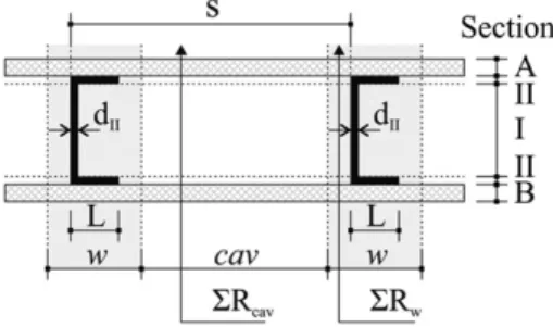
This calculation is performed using the ASHRAE standard Modified Zone Method (MZM) [8]. The MZM method takes into
consideration a zone of thermal anomalies around the metal stud that depends on the ratio between thermal resistivity of sheathing material and cavity insulation, size (depth) of stud and thickness of sheathing material. In this calculation approach, the wall cross section is divided into two zones: the zone of thermal anomalies around the metal stud (w) and the cavity zone (cav). The panel components are grouped into sections of: A: sheathing, siding; B: wallboard and sections i and ii: cavity insulation, metal studflange (Fig. 1). The width of the thermal anomaly zone (w) can be obtained using the expression:
w ¼ LþzfX
n
i¼1
di (1)
where:
w¼width of the zone of thermal anomalies (m);
L¼studflange size (m);
di¼thickness of material layer in section A (m); zf¼zone factor:
zf¼ 0.5 (forPdi16 mm and thermal resistivity of sheathing 10.4 m K/W);
zf¼ þ0.5 (forPdi16 mm and thermal resistivity of sheathing >10.4 m K/W);
When total thickness of layer of materials attached to one side of metal frame>16 mm, the value ofzfis found in the tables of the ASHRAE standard[8].
The total thermal resistance (from surface to surface) can be determined using the expression:
Rt ¼
SRw$SRcav$s
w$ðSRcav SRwÞ þs$SRw (2)
where:
Rt¼total thermal resistance (surface to surface) [(m2K)/W]; s¼distance between studs (m);
w¼width of the influence zone of the profile (m);
SRw ¼RAþRBþRIþ2$RII (3)
SRcav ¼ RAþRBþRIinsþ2$RIIins (4)
where:
RA¼thermal resistance of section A [(m2K)/W]; RB¼thermal resistance of section B [(m2K)/W]; RI¼thermal resistance of section I [(m2K)/W]; RII¼thermal resistance of section II [(m2K)/W]; RI
ins¼thermal resistance of sectionRIins[(m2K)/W]; RII
ins¼thermal resistance of sectionRIIins[(m2K)/W].
According to the ASHARE Standards [8], this method is the simplest way to calculate the LSF panel thermal resistance.
2.1.2. Calculation of the panel thermal resistance without the frame The calculation of the thermal resistance of a frameless panel is performed by considering homogeneous layers perpendicular to the heatflow (Method of Homogeneous LayerseMHL). According to the Brazilian Standard NBR 15220[9], the total thermal resis-tance between two environments can be determined using the expression:
RT ¼ RseþRtþRsi (5)
where:
RT is the total thermal resistance between environments [(m2K)/W];
Rtis the resistance from between two surfaces (e.g., the outside and inside of a wall)[(m2K)/W]; and
RseandRsiare the internal and external surface thermal resis-tances (Table 1).
2.1.3. Adjustment of the thermal conductivity (l)
The thermal conductivity of the bridged layer of a panel without a frame is adjusted so that the thermal resistance is equal to that of a panel with a metallic frame.
2.1.4. Adjustment of the density (r) and the specific heat (c) Because in the CTP method the composite layer is represented by only one material, it is necessary to adjust other thermal prop-erties. The procedure is a simplification and involves creating a new
material with modified thermal properties. In composite solids with different volumetric fractions of materials with different densities (
r
i) the densityr
sis calculated by the following equation:r
s ¼ X ni¼1
Ci
r
i (6)where:
r
sis the density of the composite solid (kg m3); Ciis the volumetric fraction of the materiali,Ci ¼ Vi
Vs (7)
and
r
iis the density of the materiali(kg/m3).The specific heat of the composite solidcscan be determined by the following equation:
Xn
i¼1
Vi
r
ici ¼ Vsr
scs (8)where:
Viis the volume of the materiali(m3);
r
iis the density of the materiali(kg/m3); ciis the specific heat of the materiali[kJ/(kg K)]; Vsis the volume of the composite solid (m3);r
sis the density of the composite solid (kg/m3); csis the specific heat of the composite solid [kJ/(kg K)];2.2. Simulation parameters
The numerical simulation was performed using Version 7.0 of EnergyPlus. The EnergyPlus program was developed by the US Department of Energy[10,11]. Many researchers use the EnergyPlus to obtain hourly site energy consumption data and the cooling load of the building[12,13]. The solution algorithm adopted for the heat balance was the CTF (Conduction Transfer Function), which considers only the sensible heat. The internal and external convection algorithms were those given by the ASHRAE Standard [8], and the time interval between each simulation point was 15 min.
Climate data used for the simulations were for the city of Belo Horizonte, Minas Gerais, Brazil, of type TRY (Test Reference Year). The data were available on the EnergyPlus website [14]. Belo Horizonte was chosen because of the constant growth in the number of LSF constructions in the region and the availability of its reliable climate data. The 6th of January and the 12th of May were chosen as representatives of a summer and a winter day,
Table 1
Internal and external superficial thermal resistance.
Rsi(m2K)/W Heatflow
Horizontally Upwards Downwards
0.13 0.10 0.17
Rse(m2K)/W Heatflow
Horizontally Upwards Downwards
0.04 0.04 0.04
Table 2
Building components.
Panel Components
External walls Cement board 10 mm
Steel stud 904012 @ 400 mm Fibreglass 90 mm
Gypsum board 12.5 mm Internal walls Gypsum board 12.5 mm
Steel stud 904012 @ 400 mm Fibreglass 90 mm
Gypsum board 12.5 mm Internal walls (core) Gypsum board 12.5 mm
Steel stud 904012 @ 400 mm Fibreglass 90 mm
Gypsum board 12.5 mm Gypsum board 12.5 mm
Ceilings Granite 10 mm
Masterboard 23 mm Air layer90 mm Fibreglass 50 mm Gypsum board 12.5 mm
Groundfloor Granite 10 mm
Concrete 150 mm
Roof Shingle 3 mm
respectively. In summer, the maximum dry bulb temperature is 29.7C, and in winter the minimum is 18.3C.
2.2.1. Composition of the panels
Thefloor slab, ceiling and roof were represented by the ther-mophysical properties, thickness and absorbance of the compo-nents. The component properties were obtained from Brazilian Standard NBR 15220[9]. The composition of the panels was set as those typically used in Belo Horizonte. The compositions of the
floor, ceiling, and roof elements are shown inTable 2.
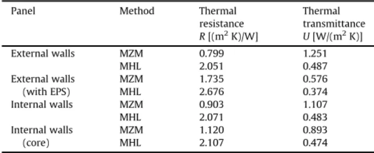
The vertical panels (walls) were characterised using the
Modi-fied Zone Method (MZM) and the Method of Homogeneous Layers
(MHL). The thermal resistances of the panels were calculated using those methods is shown inTable 3.Table 4presents the insulating layer and adjusted values of their thermal properties.
2.2.2. Cases considered
Two case studies were considered for this study. In Case 1, the goal was to investigate the effect of thermal bridging on the eval-uation of thermal loads in a commercial building. In Case 2, the objective was to analyse the effects of thermal bridging in the annual energy consumption for air-conditioning an office building with mixed concrete and metallic construction.
The model used in Case 1 corresponds to a small two-storey commercial building. Each storey has four rooms and a total area of 117.12 m2 (measured considering the external walls’ axes), a 3.50-m height and afloor sectioned by a 400 mm400 mm mesh (Fig. 2). The building was modelled in 15 thermal areas with the geometry of some areas simplified. The washrooms that
faced the eastern and western walls were grouped so that the panel that divided the washrooms was not modelled. In the circulation area the ladder was not modelled. Devices that partially block solar radiation were installed on the eastern and western walls.
People in the offices were considered as wearing clothes with a thermal resistance of 0.5 Clo (light clothes), and performing activities that released a heat rate of 130 W per person, with a radiant fraction of 0.3[15]. An internal thermal charge density rate of 20 W/m2(people: 6 W/m2; lighting: 8 W/m2; equipment: 6 W/m2) was assumed. For the non-air conditioned environments (toilets and circulation areas), only the lighting rate of 8 W/m2was used.
The usage pattern (PU) for the internal sources was considered only for working days. The beginning of activities in the building was considered to be 8:00 AM, with a break from noon to 2:00 PM and the day ending at 6:00 PM. Only the basic objects required by EnergyPlus for the calculation of thermal loads were considered. The air-conditioning system was assumed to be turned on during the day all year round. The limit constant temperature for cooling was set at 24C and the infiltration was set at 1 air change per hour renewal rate.
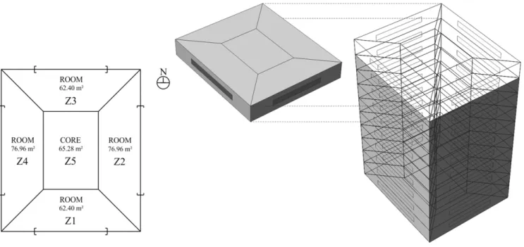
In Case 2, the LSF system has a secondary role as wall elements in the facades of a ten-storey building with a conventional concrete structure. The standard storey has a total area of 345.20 m2 (measured considering the axes of the external walls), a 3.00-m height and was divided intofive zones (Fig. 3). Thermal Zones 1 Table 3
Thermal resistance and transmittance of the vertical panels.
Panel Method Thermal
resistance R[(m2K)/W]
Thermal transmittance U[W/(m2K)]
External walls MZM 0.799 1.251
MHL 2.051 0.487
External walls (with EPS)
MZM 1.735 0.576
MHL 2.676 0.374
Internal walls MZM 0.903 1.107
MHL 2.071 0.483
Internal walls (core)
MZM 1.120 0.893
MHL 2.107 0.474
Table 4
Thermal properties of the composite layer (insulation and studs).
Bridged layer Thermal conductivity l[W/(m K)]
Specific mass
r(kg/m3) Specific heatc[kJ/(kg K)]
Exterior walls 0.120 69.778 0.563 Exterior walls
(with EPS)
0.085 69.778 0.563
Interior walls 0.108 69.778 0.563 Interior walls (core) 0.088 69.778 0.563
to 4 correspond to office rooms that are air conditioned, while Zone 5 comprises the stairway and elevators (core) and is not air conditioned. The composition of the external panels is the same as in Case 1, but the internal divisions and the slab between floors were assumed to be massive concrete with thicknesses of 10 cm and 15 cm, respectively.
A direct expansion system of theSplit-systemtype with a COP equal to 3.19 is assumed for the air conditioning system. The system operation follows the building use pattern. A control temperature of 24C was adopted for the cooling function. The maximumflow in each zone was automatically determined by the program, based on the loads generated on a design day in summer and in winter. The capacity of the cooling coil was also automatically sized. An external air flow rate per person to renew the ambient air of
0.0075 m3/s/person was assumed. The same internal load density rate and usage patterns as in Case 1 were adopted.
3. Results and discussion
3.1. Case 1: thermal bridges and thermal loads
Fig. 4presents the monthly thermal load peak, comparing the CTP and WS (without frames) values. There is a minimum variation
of 7.13% and a maximum of 22.94% between the two methods. The annual peaks of the thermal loads presented in Table 5 were obtained by applying a 25-mm thick plate of EPS (Expanded poly-styrene) on the external panels and by modifying the properties of the insulating layer.
The solar orientation of the walls with the smaller area of opaque panels, and the masking of the translucent elements facing west reduced the thermal loads. Because the air conditioning system was considered turned on during the entire day, there were no remaining loads, implying low values of the thermal load peaks.
The difference between modelling with or without the effects of thermal bridging in the size of thermal loads is 10%. This is mainly because of the difference between the internal temperature (T¼24C) and external (Tmáx¼29.7C). The application of a 25-mm layer of EPS on the external panels almost completely elimi-nates the difference between the simulations. However, the difference between the simulation results is not enough to suggest different capacities for the air conditioning system.
3.2. Case 2: thermal bridges and energy consumption
Table 6 compares the results for the annual consumption (kW h), obtained with the CTP method, WS (without frames), and when adding a layer of EPS (25 mm) on the external panels.
Energy consumption in the commercial sector is directly related to the building’s architectural features and usage patterns. The
average difference of 4.5% obtained with the representation of thermal bridging was significant considering that only the external panels were modelled with the LSF system.
Fig. 3.Typology of Case 2: schematic plan and perspective.
Fig. 4.Monthly peak of thermal load.
Table 5
Annual peak of thermal load.
Method Annual peak of
thermal load (W)
Variation (%)
CTP 3643 e
WS 3298 10.40
CTPþEPS (25 mm) 3303 10.29
In Brazil, pre-moulded concrete panels are the most usual prefabricated and industrialised wall systems, although they have the disadvantages of high cost and weight. The LSF wall system, besides allowing a better organisation and cleanliness in the jobsite, decreases the construction time. These and other criteria should also be considered when choosing a structural wall system.
4. Conclusions
The application of the CTP method to case studies of air-conditioned buildings showed that the increase in the tempera-ture difference between the inside and the outside of the building caused by the air conditioning system made the thermal bridging effects in the panels significant. When considering metal frames in the simulation, the thermal peak load increased by approximately 10%. Even when used only as wall elements in the facades of a conventional concrete structure building, the use of an LSF system in hourly thermal simulations of the structure increased the annual energy consumption by 5%. The application of a 25-mm thick layer of EPS proved to be quite efficient, almost eliminating the effects of thermal bridging.
The method has the limitation of considering only the effect of thermal bridging on vertical panels. It is well known that horizontal panels also influence the overall thermal performance of a building. The performance of the roof, for example, is influenced by the
composition of metallic frames with the roof element. However, in Brazil the thermal bridging effects in the horizontal panels are smaller than in the vertical panels due to the use of thinner insu-lating material.
The acceptance of the LSF system will occur after it is success-fully implement and the technology is disseminated to users and professionals. It is expected that this analysis of the thermal performance of buildings using LSF will contribute to the accep-tance of the system as an alternative to conventional construction systems used in Brazil.
Acknowledgements
The authors gratefully acknowledge the Fundação de Amparo à Pesquisa do Estado de Minas GeraiseFAPEMIG, Brazil.
References
[1] Alexandre Kokke Santiago, O uso do sistema light steel framing associado a outros sistemas construtivos como fechamento vertical externo não-estru-tural [The use of light steel framing system associated with other building systems such as nonstructural external vertical closing], 2008 153 f. Dissertação (Mestrado em Engenharia Civil)eEscola de Minas, Universidade Federal de Ouro Preto, Ouro Preto (in Portuguese).
[2] Holdlianh Cardoso Campos, Avaliação pós-ocupação de edificações con-struídas no sistema Light Steel Framing [Post-occupation evaluation of buildings constructed in Light Steel Framing System], 2010 164 f. Dissertação (Mestrado em Engenharia Civil)e PPGDEC, Universidade Federal de Ouro Preto, Ouro Preto (in Portuguese).
[3] Arlene Maria Sarmanho Freitas, Renata Cristina Moraes de Crasto, Steel Framing: Arquitetura (Steel Framing: Architecture), in: Série Manual de Construção em Aço, IBS/CBCA, Rio de Janeiro, 2006 (in Portuguese). [4] Adriano P. Gomes, Avaliação do desempenho térmico de edificações
uni-familiares em Light Steel Framing [Evaluation of the thermal performance of residential buildings in Light Steel Framing], 2007 172 f. Dissertação (Mes-trado em Engenharia Civil)eEscola de Minas, Universidade Federal de Ouro Preto, Ouro Preto (in Portuguese).
[5] Mark Gorgolewski, Developing a simplified method of calculating U-values in light steel framing, Building and Environment 42 (2007) 230e236. [6] Enermodal Engineering Limited, Oak Ridge National Labs, and Polish Academy
of Sciences, Modeling Two- and Three-dimensional Heat Transfer Through Composite Wall and Roof Assemblies in Hourly Energy Simulation Programs (1145-TRP), Part I, Final Report, Report prepared for ASHRAE, Atlanta, GA, 2001. [7] Julia Purdy, Ian Beausoleil-Morrison, The significant factors in modelling residential buildings, in: Building SIMULATION, 2001, Rio de Janeiro. Anais, International Building Performance Simulation Association, Rio de Janeiro, Brazil, 2001, pp. 207e214.
[8] American Society of Heating, Refrigerating and Air Conditioning Engineers (ASHRAE), ASHRAE Handbook: Fundamentals, ASHRAE, Atlanta, 1997. [9] Associação Brasileira de Normas TÉCNICAS (ABNT), NBR 15220: Desempenho
térmico de edificações (Thermal performance in buildings). Rio de Janeiro (2005) (in Portuguese).
[10] LBL, EnergyPlus Engineering Document: The Reference to EnergyPlus Calcu-lations, Lawrence Berkeley National Laboratory, US Department of Energy, May 2012.
[11] D.B. Crawley, et al., Contrasting the capabilities of building energy perfor-mance simulation programs, Building and Environment 43 (2008) 661e673. [12] N. Fumo, P.J. Mago, L.M. Chamra, Energy and economic evaluation of cooling,
heating, and power systems based on primary energy, Applied Thermal Engineering 29 (2009) 2665e2671.
[13] K.F. Fong, et al., Effect of neutral temperature on energy saving of centralized air-conditioning systems in subtropical Hong Kong, Applied Thermal Engi-neering 30 (2010) 1659e1665.
[14] DOE - U. S. Department of energy, Weather Data. Disponível em<http:// apps1.eere.energy.gov/buildings/energyplus/>(accessed in May, 2012).
[15] Associação Brasileira de Normas Técnicas (ABNT), NBR 16401: Instalações de ar-condicionado: sistemas centrais e unitários (Central and unitary air conditioning systems). Rio de Janeiro (2008) (in Portuguese).
Table 6
Annual consumption.
Method Annual consumption (kW h)
Variation (%)
CTP 12.731 e
WS 12.143 4.84
CTPþEPS (25 mm) 12.218 4.19