A
r
t
ic
le
*e-mail: [email protected]
Three Electrode Electrochemical Microfluidic Cell: Construction and Characterization
Rodrigo A. B. da Silva, Edimar G. N. de Almeida, Adriano C. Rabelo, Abílio T. C. da Silva, Lucas F. Ferreira and Eduardo M. Richter*
Instituto de Química, Universidade Federal de Uberlândia, Av. João Naves de Ávila, 2121, CP 593, 38400-902 Uberlândia-MG, Brazil
Este trabalho descreve a construção e caracterização de uma célula eletroquímica microfluídica com a inserção dos três eletrodos (trabalho, pseudo-referência e auxiliar) em microcanais com espessuras menores que 20 µm. Os microcanais foram construídos entre duas bases de policarbonato com o uso de uma ou mais máscaras de toner sobrepostas como espaçador. Esta estratégia permite a construção de microcélulas com um volume interno sobre o eletrodo de trabalho entre 0,6 a 2,4 µL. Três diferentes materiais foram otimizados como eletrodos nas microcélulas: filmes de ouro ou compósito de grafite como eletrodo de trabalho, compósito de prata como pseudo-referência e compósito de grafite como eletrodo auxiliar. O desempenho das células microfluídicas foi avaliado usando as técnicas de voltametria cíclica, redissolução potenciométrica a corrente constante e voltametria de redissolução anódica por onda quadrada empregando ferrocianeto e alguns metais pesados (Cu2+, Hg2+, Pb2+, e Cd2+) como analitos modelo.
This work describes the construction and characterizationof an electrochemical flow-through microcell with the three electrodes (working, pseudo-reference, and auxiliary) inserted in microchannels with thickness smaller than 20 µm. These microchannels were constructed between two stacked polycarbonate slides using one or more overlapped toner masks as spacer. This strategy allows the construction of microcells with a variable internal volume on the working electrode (0.6 to 2.4 µL). Three different materials were optimized as electrodes: gold film or graphite-epoxy composite as working electrode, silver-graphite-epoxy composite as pseudo-reference electrode and, graphite-epoxy composite as auxiliary electrode. The performance of the microfluidic cell was characterized by cyclic voltammetry, potentiometric stripping analysis at constant current, and square wave anodic stripping voltammetry using ferrocyanide and heavy metals (Cu2+, Hg2+,
Pb2+, and Cd2+) as model analytes.
Keywords: microfluidic cell, microchannels, gold film, graphite-epoxy composite, silver-epoxy composite, pseudo-reference
Introduction
The development of miniaturized analytical systems is a subject that has been arousing a great deal of interest of the scientific community in the area of analytical chemistry. The interest is due to many reasons, among them we may point out the reduction in production costs of each system, energy consumption, samples, reagent and residue
generated by analysis.1
A considerable number of articles that approaches this subject can be located in the literature (Web of Science). Using keywords such as “microfabrication or miniaturization or microchip or microfluid or microdevice” and directing the
search only for the title, a number of 6.149 works are listed. Narrowing the search adding to the Field address the word “Brazil”, the number reduces to only 24 works making up about 0.39% of the total, a number five times smaller than the mean of Brazilian contribution (superior to 2%). This is due, mainly, to the implementation costs of laboratories that dominate the conventional microfabrication technology, such
as high resolution photolitography.1 In Brazil, there are few
laboratories with the available infrastructure for microdevices fabrication using these techniques. The Laboratório Nacional de Luz Síncrotron (LNLS), located in Campinas/SP/Brazil is one of the rare examples where this infrastructure is available (http://www.lnls.br).
is derived from researches which use alternative methods of microfabrication. In this context, a work that may be
considered pioneer in Brazil was published by do Lago et al.2
In this paper, a process of direct deposition of toner on polyester transparency (LaserJet printer) was described for microdevices production with application in electrophoretic separations and electrospray generation. Later, Daniel and
Gutz,3 using the direct-printing process described by do
Lago et al.2 and gold surfaces obtained from gold CD-Rs4
demonstrated the possibility of gold electrode construction with different sizes using the heat-transference of toner on gold surfaces. The gold electrodes produced by this procedure are inserted in microchannels with a thickness of
some micrometers (ca. 20), with the reference and counter
electrodes positioned outside the microcell. After publication of these works, a number of new applications were presented in the literature based on this procedure. Some examples are: construction of amperometric microdetectors
for conventional capillary electrophoresis system5 and
separation microsystems manufactured in polyester toner,6
microfluidic cells with interdigitated array gold electrodes,7
generator-collector electrochemical microdevices,8-10
production of microchannels in glass,11,12 microfluidics
devices for sample treatment,13,14 new procedures for flow
rate control and sample injection in microfluidic cells,15
microelectrode arrays,16 electrodes with reproducible area,17
integration of planar electrodes for contactless conductivity
detection on polyester-toner electrophoresis microchips,18
insertion of passive micromixers in microfluidic devices19
and construction of electrochemical microcells containing the working, counter and reference electrodes in the same
device.20
In this work a simple methodology for the construction of flow through microcells with introduction of the three electrodes (working, counter and pseudo-reference) in microchannels is described. Two configurations of microcells are presented. In the first, the working electrode inserted in the microchannel is a thin gold film while in the second it is graphite composite. In both cases, the pseudo reference and auxiliary electrodes are constituted of silver and graphite composite, respectively. The potentiality of the devices was evaluated by analyses of model analytes, resulting in similar results to those obtained with conventional electrochemical cells.
Experimental
Solutions and reagents
All solutions were prepared with deionized water
(resistivity = 18 MΩ cm) obtained by MilliQ.plus
(Millipore) purification system. The solutions were prepared with analytical grade reagents (Merck or
AnalytiCals). A solution containing 0.5 mol L-1 KCl and
6.0 mmol L-1 HCl was used as supporting electrolyte for
simultaneous analysis of copper and mercury. Cadmium
and lead analysis were carried out using 0.1 mol L-1 acetate
buffer (pH 4.7) containing 2.0 mg L-1 of bismuth (formation
of film in situ) as supporting electrolyte.21 In the studies
with potassium ferricyanide, the supporting electrolyte was
0.1 mol L-1 of KCl.
The procedure for the graphite composite fabrication
was the following: (i) 0.1 g of Epoxy resin (Araldite®
24 h, Brascola) was added to 3.0 mL cyclohexanone under
stirring (5 min); (ii) Next, slowly (10 min) and under
constant stirring, 0.1 g of poliaminoamide was added;
(iii) Finally, 2.0 g of graphite powder (Aldrich, particles
diameter, 1-2 µm) was slowly added, keeping the mixture under stirring for 24 h.
Before use, the graphite composite was painted on the surface of interest and cured at room temperature (about 24 h). The silver glue (PC 9045) used in this work was obtained from Joint Metal Comércio Ltda company (Diadema/SP).
Instrumentation and flow system
The electrochemical experiments were performed using a µ-Autolab Type III (Eco Chemie) potentiostat, interfaced with a microcomputer and controlled by GPES 4.9 software. To print and to perform the heat transference of the toner masks, a printer HP LaserJet 1160 and a thermal press model Prima (Ferragini Design) were used, respectively. For the hydrodynamic experiments using techniques, such as potentiometric stripping analysis at constant current, square-wave anodic stripping voltammetry and cyclic voltammetry, the flow rate was controlled using a constant pressure generated by an aquarium pump. The air from the pump was bubbled into a water column connected to a closed mini bottle containing the carrier electrolyte. This artifice minimizes flow pulsation, a very important issue in experiments
using microdevices with electrochemical detection.22
The pressure generated by the system is transferred to a mini bottle and consequently the solution is pushed to the microcell through the fused silica capillary tubing with 250 µm of internal diameter. To change sample or standard solution, only the body of mini bottle is substituted, the top remain in place. Stripping analysis was performed without flow stop (without pulsation). A miniaturized Ag/AgCl, sat. KCl was used as a conventional reference
Construction of microcell using gold film as working electrode
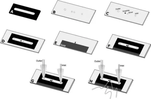
Figure 1 shows the fabrication process of the microcell using a gold film as working electrode, graphite composite as counter electrode and silver composite as pseudo-reference electrode. The process follows the next steps: (A) The image of the toner mask (spacer) is drawn at 1:1 scale using graphic software. Then, it is printed using an HP LaserJet 1160 series on a waxed paper of the type used as support (base material) for self adhesive labels. This mask defines the width and height of the microchannel. The width (5.0 mm) is defined by the toner-free area in the center of mask and the height by the toner thickness. The height of the microchannel is controlled by the following way: one
mask ca. 6 µm; two overlapping masks ca. 12 µm; three
masks ca. 17 µm; four masks ca. 22 µm. Previous studies
have demonstrated that it is possible to reach 45 µm of
height.7,8,10 (B) Using the same procedure described in (A),
another mask that defines the positioning of counter and pseudo reference electrodes, as well as the orifice of inlet and outlet of the solution is drawn. The mask, once printed, is heat transferred to a polycarbonate substrate, obtained from recordable CDs (after removal of the silver film). The orifices are made at the positions exactly indicated by the mask; 0.9 mm of diameter for the solution inlet, counter and pseudo-reference electrodes. The diameter of the orifice
for the solution outlet is 2 mm. (C) The polycarbonate substrate (with orifices) is polished with water sandpaper (grade 600) to remove possible imperfections generated during the drilling process. The intermediate orifices are filled, one with graphite composite and the other with silver composite, to use as counter and reference electrodes, respectively. These composites need to be dried at room temperature for 24 h. A new polishing step is necessary to ensure a flat surface. (D) Heat transference of the toner mask described in step (A) to the substrate described in step (C). (E) Polycarbonate substrate covered partially with a thin gold film. This substrate is obtained in agreement
with procedures described previously.3,5 (F) Junction (by
heating) of substrates described in steps (D) and (E). The gold electrode must be positioned between and in front (opposed side) of the silver and graphite composite electrodes. To reinforce the structure of the microdevice,
an epoxy adhesive (Araldite® 10 min) is used to cover the
microdevice body. (G) With the same epoxy adhesive, micro-tips are glued to the inlet and outlet sides. At the inlet side, a fused silica capillary tubing with 250 µm of internal diameter is immobilized. At the outlet side, polycarbonate tubes having greater internal diameters may be used. (H) Fixation of copper wires, using the graphite or silver conductor composite, are employed to allow the electric contact between electrodes and the potentiostat.
Construction of microfluidic cell using graphite composite as working electrode
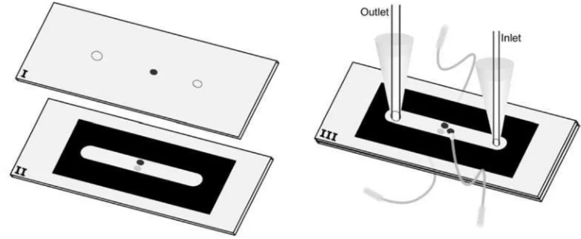
Figure 2 shows the steps involved in the construction of a microfluidic cell when the gold working electrode (Figure 1) is substituted by graphite. Many steps of the construction are identical to the ones shown in Figure 1, as follows. (I) Acquisition of a polycarbonate substrate from a common CD-R. Implementation of three orifices:
for solution inlet (∅ = 0.9 mm), outlet (∅ = 2.0 mm)
and, the third one (intermediary; ∅ = 0.9 mm) for the
introduction of the graphite composite (working electrode). (II) In another polycarbonate substrate, two orifices
(∅ = 0.9 mm) are drilled side by side. One is filled with
graphite composite (counter electrode) and another with silver composite (pseudo reference). After polishing, the same toner mask used in the Figure 1A is heat-transferred to this substrate. (III) Join (‘‘sandwich”) the two substrates (I and II) by heating using a thermal press. The other steps (use of epoxy adhesive to mechanic reinforcement, fixation of micro-tips and electric contact) are the same as that one shown in Figure 1.
Results and Discussion
The microfluidic cell described in Figure 1 (with two toner layers overlapped as spacer) was characterized by cyclic voltammetry using potassium ferrocyanide as model analyte and KCl as supporting electrolyte. The performance of the pseudo-reference electrode (silver composite localized in one orifice at the upper side of the microcell) was characterized comparing the signals obtained when the pseudo-reference electrode was substituted by a
conventional reference electrode (Ag/AgCl, KCl sat.).23
In this case, the micro-tip located at the outlet side of the
microcell was substituted by a small reservoir with 1.5 mL capacity, where the conventional reference electrode was inserted. Figure 3 shows the obtained results.
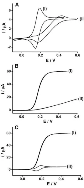
As we can observe in Figure 3, using stationary (3A) or hydrodynamic (3B) cyclic voltammetry, a displacement occurs in the peaks potentials of the iron(II)/iron(III) redox couple to negative potentials when the pseudo-reference silver composite electrode (I) is used in substitution to the conventional reference electrode (II). This is in agreement
with previous studies.20 Moreover, the performance of the
microfluidic cell was better when the pseudo reference electrode was used (located inside the microchannel), both with respect to sensibility and reversibility of the redox couple (ferro/ferricyanide). For cyclic voltammograms conducted in the stationary mode (Figure 3A), the total current measured changed from 5.83 to 8.75 µA, when the conventional reference electrode was substituted by the silver composite pseudo-reference electrode. This represents an increase of 50% in the faradaic current. Another significant improvement is observed in the difference between the
cathodic and anodic peak potentials, ∆E, which changed
from 180 to 45 mV when the conventional reference electrode, positioned outside the microchannel, was substituted by silver composite pseudo-reference electrode (positioned in the interior of the microchannel). The use of the silver composite pseudo-reference electrode inside the microchannel reduces significantly the distance between the working and reference electrodes and, consequently, the resistance between them.
Cyclic voltammetry studies conducted in the stationary mode when compared to the results obtained in the hydrodynamic mode (Figure 3B), revealed the microcell performance using a silver composite pseudo-reference electrode presents better response when compared with the conventional reference electrode, showing an increase of
the faradaic current of 350% (17.1 to 60.2 µA). Moreover, the distortion of the voltammogram in the hydrodynamic mode (under constant flow rate) using the conventional reference electrode, was greater than the stationary cyclic voltammetry. The improvement of sensibility and reversal behavior of the system can be attributed to the fact that the silver composite pseudo-reference, which is positioned inside the microchannel near to the working and counter electrodes, generates a smaller resistance resulting in a smaller ohmic drop. This is a reasonable explanation considering that the distance between the working and
reference electrodes increases significantly when it is positioned outside of the microchannel. It is important to remember that a distance up to 1.0 cm between electrodes in a conventional cell is acceptable because of the volume of solution (contact area) between the electrodes, which is quite different from the microdevice when the electrodes are inserted into microchannels with one of the dimensions smaller than 20 µm.
The use of hydrodynamic flow improves significantly the detection limit of the analytical methodologies when electrochemical techniques are used. This feature represents an important aspect when electrochemical microcells are used, when reduced volumes of solution are in contact with the working electrode (in order of nanoliters). This behavior is illustrated in Figure 3C, where the results of cyclic
voltammetric experiments, using 1.0 mmol L-1 potassium
ferrocianide as model analyte, in hydrodynamic (I) and stationary mode (II), are compared. The current signal in
the hydrodynamic mode (flow rate = 60 µL min-1) is 7 times
higher than in the stationary mode (8.7 to 60.2 µA). Other experiments to verify the potentiality of the constructed microfluidic cell using two toner layers as
spacer (ca. 12 µm) aiming at the quantification of heavy
metals, such as copper and mercury, were conducted. The option for these ions as model analytes is supported by the potentiality of the gold working electrode used in the microcell to analyze these metals, as described in
the literature.24,25 Figure 4 presents the signals obtained
for the simultaneous analysis of copper and mercury using potentiometric stripping analysis at constant current as function of the increasing concentrations
of both metals (10, 20, 30, 40 and 50 µg L-1). These
chronopotentiograms were recorded using a flow rate of
60 µL min-1 and deposition time of 60 s. A comparison
between the performance of the flow-through microcell
with a conventional flow-through cell26 shows a similar
sensitivity for both cases, however, the flow rate necessary for the conventional cell to present the same response
must be superior to 3.0 mL min-1. These results clearly
evidence that the use of the microcell permits an economy of reagents and samples of up to 50 times, decreasing the generation of residues of the same magnitude. Using a microcell with the microchannel defined by one toner mask (6 µm of thickness) obviously reduces further, the consumption of samples and/or reagents, however, also increases the difficulty to operate the microcell.
The characterization of the microcell with a graphite composite working electrode inserted in the microchannel (4 toner masks overlapped as spacer) was done using
cadmium and lead as model analytes in 0.1 mol L-1 acetate
buffer and 2 mg L-1 of bismuth (in situ thin film formation).
Figure 3. Cyclic voltammograms recorded in 1 mmol L-1 potassium
ferrocyanide and 0.1 mol L-1 KCl. (A) Voltammograms recorded in
the stationary mode using (I) silver composite positioned inside the microchannel as pseudo-reference electrode or (II) Ag/AgCl (sat. in KCl)23 positioned out of the microchannel; (B) idem to previous item (A),
however under hydrodynamic conditions, 60 µL min-1; (C) Comparison
Figure 4. Signals obtained using potentiometric stripping analysis at constant current as function of increasing copper and mercury concentrations (10, 20, 30, 40 and 50 µg L-1) in 0.5 mol L-1 KCl and
6.0 mmol L-1 HCl. Deposition time: 60 s; Deposition potential: −0.1 V;
Constant current: 1 µA; Flow rate: 60 µL min-1; Correlation coefficients
(Cu = 0.997 and Hg = 0.995).
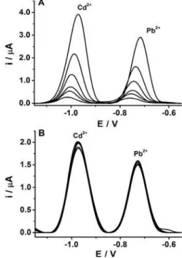
Figure 5. Signals obtained using square wave anodic stripping voltammetry in 0.1 mol L-1 acetate buffer and 2.0 mg L-1 of bismuth
(pH 4.7). Deposition time: 180 s; Deposition potential: −1.7 V; Flow rate: 60 µL min-1; (A) Voltammograms as function of cadmium and lead
concentrations (10, 16, 20, 30, 50 and 100 µg L-1); Correlation coefficients
(Cd = Pb = 0.996); (B) Repetitive voltammograms obtained for 50 µg L-1
of Cd2+ and Pb2+. Relative standard deviation: 1.0% (n = 8).
Figure 5A shows the signals obtained by square wave
anodic stripping voltammetry as function of the Cd2+ and
Pb2+ concentration (10, 16, 20, 30, 50 and 100 µg L-1).
Linear regression equation were Ipa (µA) = −0.0614 +
0.0453 C (µg L-1) and I
pa (µA) = −0.0068 + 0.0331 C (µg L
-1)
for Cd2+ and Pb2+, respectively, with a correlation coefficient
of r = 0.996 for both analytes. The detection limit (S/N=3)
were 0.38 and 0.74 µg L-1 for Cd2+ and Pb2+, respectively.
Figure 5B shows the results of a reproducibility study
for repetitive analysis of solutions containing 50 µg L-1
of Cd2+ and Pb2+ (n = 8). The relative standard deviation
calculated was around 1.0% for both analytes. The use of silver composite as pseudo-reference electrode did not cause a significant variation in the peak potential for both analytes, confirming the good performance of this material for this application.
Conclusions
In this work we report a simple and easy procedure to construct microfluidic electrochemical cells with three electrodes inserted inside a microchannel that compose a voltammetric cell. In the construction process of these microdevices, inexpensive materials are used, such as: policarbonate substrates obtained from recordable compact discs (covered or not with a thin gold layer), LaserJet printer, thermal press, epoxy adhesive, graphite powder and silver composite. Due to the low production costs of each microcell, one can consider this as a construction process for disposable devices. Despite the use of alternative and low cost materials, the results obtained using this microdevice presents good potentiality for heavy metals
analysis, like Cu2+, Hg2+, Cd2+ and Pb2+ at trace levels with
low consumption of reagents and samples.
Acknowledgments
The authors thank the Fundação de Apoio à Pesquisa do Estado de Minas Gerais (FAPEMIG), the Coordenação de Aperfeiçoamento de Pessoal de Nível Superior (CAPES) and the Conselho Nacional de Desenvolvimento Científico e Tecnológico (CNPq) for financial support and Dr. Julien F. C. Boodts for the English revision.
References
1. Coltro, W. K. T.; Piccin, E.; Carrilho, E.; de Jesus, D. P.; Fracassi da Silva, J. A.; Torres da Silva, H. D.; do Lago, C. L.; Quim. Nova2007, 30, 1986.
2. do Lago, C. L.; da Silva, H. D. T.; Neves, C. A.; Brito-Neto, J. G. A.; da Silva, J. A. F.; Anal. Chem.2003, 75, 3853. 3. Daniel, D.; Gutz, I. G. R.; Electrochem. Commun.2003, 5,
782.
4. Angnes, L.; Richter, E. M.; Augelli, M. A.; Kume, G. H.; Anal. Chem.2000, 72, 5503.
5. Richter, E. M.; da Silva, J. A. F.; Gutz, I. G. R.; do Lago, C. L.; Angnes, L.; Electrophoresis2004, 25, 2965.
7. Daniel, D.; Gutz, I. G. R.; Talanta2005, 68, 429.
8. Paixao, T.; Richter, E. M.; Brito-Neto, J. G. A.; Bertotti, M.;
Electrochem. Commun. 2006, 8, 9.
9. Ferreira, T. L.; Paixao, T.; Richter, E. M.; El Seoud, O. A.; Bertotti, M.; J. Phys. Chem. B2007, 111, 12478.
10. Paixao, T.; Richter, E. M.; Brito-Neto, J. G. A.; Bertotti, M.;
J. Electroanal. Chem.2006, 596, 101.
11. do Lago, C. L.; Neves, C. A.; de Jesus, D. P.; da Silva, H. D. T.; Brito-Neto, J. G. A.; da Silva, J. A. F.; Electrophoresis2004,
25, 3825.
12. Coltro, W. K. T.; Piccin, E.; da Silva, J. A. F.; do Lago, C. L.; Carrilho, E.; Lab Chip2007, 7, 931.
13. de Jesus, D. P.; Blanes, L.; do Lago, C. L.; Electrophoresis
2006, 27, 4935.
14. Daniel, D.; Gutz, I. G. R.; Electrochem. Commun.2007, 9, 522.
15. Daniel, D.; Gutz, I. G. R.; Anal. Chim. Acta2006, 571, 218. 16. Richter, E. M.; Munoz, R. A. A.; Bertotti, M.; Angnes, L.;
Electrochem. Commun.2007, 9, 1091.
17. Lowinsohn, D.; Richter, E. M.; Angnes, L.; Bertotti, M.;
Electroanalysis2006, 18, 89.
18. Coltro, W. K. T.; da Silva, J. A. F.; Carrilho, E.; Electrophoresis
2008, 29, 2260.
19. Liu, A. L.; He, F. Y.; Wang, K.; Zhou, T.; Lu, Y.; Xia, X. H.;
Lab Chip2005, 5, 974.
20. Ferreira, H. E. A.; Daniel, D.; Bertotti, M.; Richter, E. M.;
J. Braz. Chem. Soc.2008, 19, 1538.
21. Kefala, G.; Economou, A.; Voulgaropoulos, A.; Sofoniou, M.;
Talanta2003, 61, 603.
22. dos Santos, W. T. P.; Ceolin, M. P.; de Albuquerque, Y. D. T.; Richter, E. M.; Quim. Nova2007, 30, 1754.
23. Pedrotti, J. J.; Angnes, L.; Gutz, I. G. R.; Electroanalysis1996,
8, 673.
24. Jena, B. K.; Raj, C. R.; Anal. Chem.2008, 80, 4836.
25. Augelli, M. A.; Munoz, R. A. A.; Richter, E. M.; Cantagallo, M. I.; Angnes, L.; Food Chem.2007, 101, 579.
26. Richter, E. M.; PhD Thesis, Universidade de São Paulo, São Paulo, Brazil, 2004. (www.teses.usp.br/teses/disponiveis/46/46133/ tde-26092006-114024/)