Artigos Gerais
A measurement of
g
with a ring pendulum
(Medida degcom pˆendulo anular)
R. De Luca
1and S. Ganci
2Dipartimento di Fisica “E.R. Caianiello”, Universit`a degli Studi di Salerno, Fisciano, SA, Italy 2
Studio di Catalogazione e Conservazione Strumenti Scientifici, Casarza Ligure, GE, Italy Recebido em 29/12/2010; Aceito em 12/7/2011; Publicado em 28/9/2011
A classical problem in mechanics, in which a solid ring of negligible thickness may oscillate around two axes, is studied. Simple and accurate measurements of the periods of oscillation about two different axes provide both a convincing check of the main features of this problem-solving example and a measurement of g. A simple
photogate system and “Creative Wave Studio”, an improperly used software, allows accurate measurements of the periods of oscillation. The experiment is designed as an undergraduate student’s laboratory activity, but it can be equally used and discussed as a classroom experiment.
Keywords: classical mechanics, measurement ofg, ring pendulum.
Estudamos neste artigo um problema cl´assico da mecˆanica na qual um anel s´olido, de espessura desprez´ıvel, pode oscilar em torno de dois eixos. Medidas simples e precisas dos per´ıodos de oscila¸c˜ao em torno dos dois diferentes eixos fornecem n˜ao apenas uma comprova¸c˜ao convincente das caracter´ısticas principais deste exemplo de problema sol´uvel como tamb´em propiciam uma medida deg. Um simples sistema de porta de luz junto ao
“Creative Wave Studio”, um software comumente usado de maneira impr´opria, permitem que fa¸camos medidas precisas dos per´ıodos de oscila¸c˜ao. O experimento ´e feito pensando em uma atividade de laborat´orio para estu-dantes de gradua¸c˜ao, mas pode ser igualmente usado e discutido em sala de aula.
Palavras-chave: mecˆanica cl´assica, medida deg, pˆendulo anular.
1. Introduction
There is a problem in classical mechanics [1], involving a thin solid ring supported by a knife edge at a point, in which the ring may oscillatein twofold way. The so-lution is aimed to finding the two periods of oscillation, showing that the ratio of these periods is a constant. A determination of the acceleration due to gravity g fol-lows, within the small oscillations approximation, from the analytic expression of the periods of oscillation. The problem has a pedagogical value because it involves se-veral concepts as the so called “parallel axis theorem” and a direct evaluation of the moment of inertia as a useful Trigonometry exercise. In addition, if a simple photogate system is used through the PC sound card and an audio software as “Creative Wave Studio” is improperly used as anaccuratetimes datalogger, a low cost experiment follows. By this experimental setup one can concretely show that small oscillations are not isochronous compared to large oscillations of the ring pendulum. Moreover, in the special case of small os-cillations, a good measurement of gcan be given. The experiment can be considered as a students’ Lab
ac-tivity or used and discussed as classroom experiment complementary to problem-solving practice. The time resolution of the software, which in our case is impro-perly used, provides a rather effective mean to show to students the difference in the periods when large and small oscillations are considered.
2.
The analytical problem
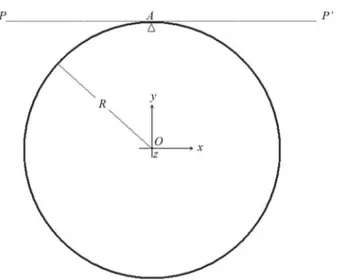
In Fig. 1 the geometry of the problem is shown. Thez
axis is taken orthogonal to the paper sheet and oriented outward. In the first problem the point A is the knife edge suspension, in such a way that the ring may oscil-late in thez= 0 plane about point A (namely, around an axis orthogonal to the paper sheet through A). In the second problem the ring is pivoted by an axis PP’ lying in the paper sheet plane and executes oscillations in and out this plane. In practice, a knife edge suspen-sion at A may be used in both cases using a little care in the second case, in order to avoid undesired rotational effects (ring oscillations around PP’ axis alone).
Let solve the first problem. The moment of inertia
IzO around the zaxis can be easily evaluated to be
1
E-mail: rdeluca@unisa.it.
Figura 1 - The geometry of the oscillation problem. In the first problem the ring suffers a knife edge suspension at point A and oscillates in thez= 0 plane about point A (namely around an axis orthogonal to the paper sheet through A). In the second problem the ring (still suspended at A) oscillates around an axis PP’ lying in the paper sheet, executing oscillations out thex−y plane and orthogonally to it. In practice, a knife edge suspension at A may be used in both cases using a little care in the second case to avoid undesired rotational effects.
IzO=λR3
2π
∫
0
dφ=M R2, (1)
being λ the linear mass density and Rdϕ the infinite-simal length element. By the parallel-axis theorem [2], the moment of inertiaIzA around an axis parallel toz
through A is
IzA=IzO+M R2= 2M R2. (2)
Let us allow an angular displacement ϑ out of the equilibrium of the ring. The fundamental equation of a rigid body dynamics applied to this special case gives
IzAϑ¨=−M gRsinϑ (3)
giving the linear equation
¨
ϑ+ g
2Rϑ= 0 (4)
in the special case of small oscillations. Hence the pe-riodT1 of small oscillations is given by
T1= 2π √
2R
g (5)
A student may observe that a direct calculus of the moment of inertia considering Aas a fixed polar axis is easily obtained by taking into account the geometry in Fig. 2. In fact, with reference to the triangle in Fig. 2 one can write
r= 2Rcosϑ, (6)
Figura 2 - The geometry for a direct calculating the moment of inertia around a pivot at A (see Eqs. (6) and (7)).
beingrthe distance from A to an infinitesimal element
dl on the right half circumference. Since dl =Rd(2ϑ) (see geometric relation betweendϑandd(2ϑ) in Fig. 2), it is easy to evaluate the moment of inertia (with respect to a fixed polar axis A) of the half circumference. The calculation gives
1
2IzA= 2λR
3
π/2 ∫
o
cos2ϑdϑ=M R2. (7)
Finally, by doubling this results for the entire cir-cumference, Eq. (2) follows. Using the parallel-axis theorem it follows that the moment of inertia around PP’ axis is
IP P′ =IxO+M R2, (8)
being IxO =MR2/2 the moment of inertia referred to
a rotation around the xaxis as follows by direct eva-luation. Hence the moment of inertia around the axis PP’ is
IP P′ =
3 2M R
2. (9)
Considering again Eq. (3), the period T2 of small
oscillations around PP’ axis becomes
T2= 2π √
3R
2g. (10)
Finally, the constant ratio of the two periods is
T1
T2
= 2
√
3
3.
The experiment
The experiment can be performed using an iron ring (in our case 360 mm ±1.3 mm outer diameter) and a cutter blade as knife edge suspension, in order to obtain oscillations with low damping. The experimental setup assembled for the special case ofz= 0 plane oscillations (in-plane oscillations) is shown in Fig. 3. Oscillations related to the first problem do not require particular care in maintaining a stable plane of oscillation; only little care is required when the ring is released from a position out of equilibrium. A satisfying solution may be realized with a small electromagnet or, more sim-ply, with a sewing tread holding: the ring can be, in this way,gently released from its equilibrium position. Oscillations starting from a big initial angular displa-cement (about 45◦) show a stability of about half an
hour; after this interval of time the amplitude of oscil-lations reduces to that of a small angle approximation (about 5◦). A photogate system can be made with a
reverse-biased photodiode and a laser pointer illumina-ting it.2 At each light interruption event, the signal
of few millivolts appearing across the photometric cir-cuit resistance is fed into the “audio card” jack socket. A suitable audio software, as “Creative Wave Studio”, will thus record a peak in correspondence to each light interruption event. In this way, we may collect a se-ries of peaks, one for each half oscillation time interval. “Creative Wave Studio”, improperly used in this way, may provide time measurements with uncertainties of few milliseconds.3 Moreover, using a suitable zoom, it
is possible to measure a set of 40-60 peaks taken in vari-ous time regions of the oscillation history (characterized as great and small amplitude regions), thus obtaining a set of periods of oscillations. From a set of 50 or more measurements, a significant value of the periodT1and
the standard deviation associated to this set of mea-surements may be found. In Fig. 3 the experimental setup for the first problem is shown. Recording of the oscillation periods relative to the first problem has been interrupted when the oscillation amplitude was under a few degrees.
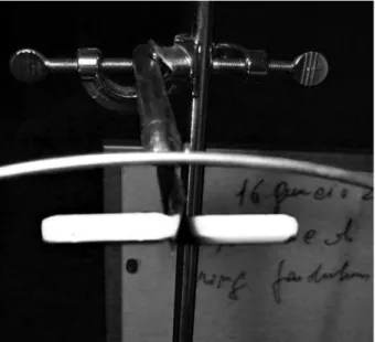
The same cutter blade as knife edge suspension has also been used for the out-of-plane oscillation mode (i.e., when ring displacement is aligned with the knife edge but the plane containing the ring is obviously uns-table in time). A practical solution in stabilizing the oscillations around the PP’ axis is given by a pair of li-near magnets attached at a pole to the cutter blade and near the ring arc suspended by the knife edge as shown in Fig. 4. Because the ring is made of iron, the light at-traction exerted by the linear magnets maintains a
suf-ficient stability in the oscillation but introduces some additional damping. In this second case damping gives about 5 minutes of measurable small amplitude oscil-lations. Fig. 4 shows the way two “Geomag” magnets are placed on a large cutter blade.
Figura 3 - The experimental setup assembled on a workbench. A laser pointer coupled with photodiode system on the lab jack is shown. In the in-plane oscillating pattern the beam of the laser pointer impinges on the ring when it passes through it equili-brium position at a distance equal to the ring’s radius from the center on thex-axis.
Figura 4 - The detail of two “Geomag” magnets assembled at the knife edge (a large cutter blade) to stabilize out-of-plane oscilla-tions in a direction orthogonal to thexyplane of the Fig. 1. The magnets exerts a little attraction on the ring near the knife edge. This attraction avoids undesired deviation in time of the axis PP’ in Fig. 1, but introduces additional damping in the system.
2
ABX 65Silicon photodiode in series with a resistanceRof about 20 k. A 9 V battery is connected to a reversed biased photodiode. A low power 670 nm Laser pointer is assembled in front of the photodiode. The signal pick up from the resistorRis fed into the PC’s MIC socket.
3
4.
Check between theory and practice
For the special case of the first problem oscillation starts from an angle of about 45◦and the laser pointer beam is
periodically interrupted by the oscillating ring. The sig-nal across the resistance in series with the photodiode is fed into the audio card with the software “Creative Wave Studio” running. In a typical experimental run, large oscillations survive for about a half-hour period. By selecting a convenient zoom factor on the software and by recording about 40-60 complete “electric peaks” relative to complete oscillations, a measurement of the period of the oscillationT1is possible with a maximum
uncertainty of 2 ms per group. A set of 50 groups of “electric peaks” can be selected in the domain of the os-cillations having great amplitude (around 40◦) and 50
groups of “electric peaks” can be selected in the domain of small amplitude (under 5◦). In a typical measure a
significant difference in the periodT1 is detected. The
mean value of T1 found for great oscillations is T1 =
1.231 s±0.004 s, where the uncertainty is assumed to be the standard deviation on the series of 50 measu-rements. Analogously, the mean value of T1 found for
small oscillations isT1 = 1.206 s ±0.005 s, where the
uncertainty is again the standard deviation on the series of 50 measurements in the domain of small oscillations. So, the so called “small oscillation” approximation has a concrete checking in the measurements done.
If a measurement is made for small oscillations (un-der 5◦) around the PP’ axis by still selecting groups of
50 groups of “electrical peaks”, the periodT2 found in
a typical measurement isT2= 1.037 s ±0.005 s, where
uncertainty is still the standard deviation on the series of the 50 measurements considered. The experimental ratio is thusT1/T2 = 1.16±0.01 and agrees with the
theoretical value given by Eq. (11) within the uncer-tainty width.
The value of the acceleration due to gravity g fol-lowing from Eq. (5) is found to be
g≈9.8 m/s2±0.1 m/s2. (12) On the other hand, the value ofgfollowing from Eq. (10) is found to be
g≈9.9 m/s2±0.1 m/s2. (13) In both cases the relative uncertainty is calculated as follows
dg g =
dR R + 2
dT
T , (14)
by takingdR= 1.3 mm anddT = 0.005 s.
5.
Correction due to the ring thickness
In Section 2 we have considered a very thin ring. In or-der to see how the measurement ofgare affected by the
mass distribution of the torus, we may use the following expressions of the moments of inertia as calculated for the in-plane (IzO) and the out-of-plane (IxO)
oscillati-ons
IzO =M c2
(
1 + 3 4λ
2 )
, (15a)
IxO=
M c2
8
(
4 + 5λ2)
, (15b)
where c =R+a, R and abeing the inner radius and the cross section radius of the torus, respectively, and whereλ= c
a. By addingM R
2=M c2(1
−λ)2 to both terms, as prescribed by the parallel axis theorem, we have
IzA=M c2
[(
1 +3 4λ
2 )
+ (1−λ)2
]
, (16a)
IxA=M c2
[(1 2 + 5 8λ 2 )
+ (1−λ)2
]
. (16b)
To first order inλ, we can therefore write
IzA= 2M c2(1−λ), (17a)
IxA=M c2
(
3 2 −2λ
)
. (17b)
Recalling now Eq. (3), for small oscillations we have
T1= 2π √
IzA
gR = 2π
√
2c
g , (18a)
T2= 2π √
IxA
gR = 2π
√
(3−4λ)c
2 (1−λ)g. (18b)
In this way, by calculatinggfrom the above expres-sions, we obtain
g= 9.7m/s2±0.2m/s2; (19a)
g= 9.8m/s2±0.2m/s2, (19b)
where the uncertainty has been calculated by conside-ring the sum of the relative uncertainties as follows
dg g =
dc c + 2
dT T =
dR R +
da a + 2
∆T
T , (20)
6.
Conclusions
We have performed an experiment on the period of os-cillations of a ring pendulum. Both the in-plane period
T1 and the out-of-plane period T2 were measured by
acquiring data through an improper use of “Creative Wave Studio” software. This data acquisition system is coupled to a photometric resistance across which a voltage signal of few millivolts appears each time an opportunely positioned photogate system is obscured by the oscillating ring. Measurement of the periodsT1
andT2in the limit of small oscillations provide a mean
to measure the acceleration due to gravity g. Moreo-ver, by analyzing the problem from an analytic point of view, we may derive, for a very thin ring, the expres-sion for the ratio of the two periods, which is in good agreement with experimental findings. The value of g
is found within the uncertainty width estimated for it. Correction due to the ring thickness has also been considered. When this problem is tackled, one finds that the relative uncertainty is greater than the one found for the “ideal” problem of a very thin ring. This last step adds some pedagogical value to the experi-ment. In fact, the student may concretely see how, by the refinement of the analysis of the problem, an in-crease of the uncertainty due to correction factors is introduced.
Referˆ
encias
[1] A.M. Alpern, 3000 Solved Problems in Physics (McGraw-Hill, New York, 1988), p. 236-237.