ABSTRACT: This paper presents a comprehensive study on the performance analysis of 8 conceptual guidance laws for exoatmospheric interception of ballistic missiles. The problem is to ind the effective thrust direction of interceptor for interception of short-to-super range ballistic missiles. The zero-effort miss and the generalized required velocity concept are utilized for interception of moving targets. By comparison of the 8 conceptual guidance laws, the thrust direction is suggested to be in the direction of generalized velocity-to-be-gained, or constant velocity-to-be-gained direction, rather than to be in the direction along zero-effort miss, or that of linear optimal solution for long-to-super range interception. Even for short coasting ranges, the generalized velocity-to-be-gained may be utilized because of reasonable computational burden for required velocity rather than the numerical computation for zero-effort miss or linear optimal solution with the same miss distance error. In addition, the fuel consumption of the suggested direction has less sensitivity due to estimation error in intercept time. The guidance law based on constant velocity-to-be-gained direction and the optimal solution are suitable for satellites launch vehicles and space missions.
KEYWORDS: Exoatmospheric midcourse guidance, Effective thrust direction, Zero-effort miss, Velocity-to-be-gained, Long-range interceptor, Anti-ballistic guidance.
Evaluation of Conceptual Midcourse
Guidance Laws for Long-Range
Exoatmospheric Interceptors
Mohsen Dehghani Mohammad-abadi1, Seyed Hamid Jalali-Naini1INTRODUCTION
Exoatmospheric intercept guidance improvements are of high interest in anti-ballistic air defense systems. he main subjects in this area are focused on midcourse and terminal phases of flight for anti-ballistic interceptors. The design considerations for the midcourse guidance are diferent from the terminal phase one. In the midcourse phase, the on-board trajectory optimization and trajectory shaping are the main issues, whereas the noise contamination and hit probability against very-high speed targets are the key issues for a terminal guidance law (Zarchan 2012).
The literature on exoatmospheric intercept guidance laws can be categorized into intercept guidance laws against moving targets and guidance laws for space missions including ballistic missiles. Since the concepts and guidance algorithms of ballistic missiles are similar to space vehicle guidance laws, we put them in the same category. he early literature on the subject of optimal 2-point guidance for interception of moving targets is based on zero-efort miss (ZEM) in lat-Earth model (Bryson and Ho 1975). In this case, the acceleration command in the optimal energy problems is obtained proportional to ZEM vector. Precisely speaking, the commanded acceleration of optimal energy guidance laws with inal constraints in linear systems is obtained in the form of the predicted error vector pre-multiplied by a gain matrix. In the case that the final position vector is only constrained, the solution simpliies to ZEM vector pre-multiplied by a time-varying gain matrix (Rusnak and Meir 1991). In a special case, if the airframe and control systems are assumed to be identical for 3 axes, the matrix gain
1.Tarbiat Modares University – Faculty of Mechanical Engineering – Aerospace Group – Tehran/Tehran – Iran.
Author for correspondence: Seyed Hamid Jalali-Naini | Tarbiat Modares University – Faculty of Mechanical Engineering – Jalal Al Ahmad Street, No 7 | P.O. box14115-111 – Tehran/Tehran – Iran | E-mail: [email protected]
simplii es to a scalar, i.e. the commanded acceleration becomes proportional to ZEM (Rusnak and Meir 1991). Two classes of explicit guidance laws based on ZEM have been developed with dif erent assumptions for interceptor dynamics and types of target maneuvers (Jalali-Naini 2004).
In spherical-Earth model, in spite of the assumption of a perfect control system, the optimal maneuver is not obtained in the direction of ZEM because of the non-linear nature of the gravitational acceleration. Most literature on exoatmospheric intercept problems utilized the ZEM vector as an ef ective direction for thrust vectoring of the interceptor (Massoumnia 1995; Feng et al. 2009; Li et al. 2013). h e ZEM can be approximated in an inverse-square gravity i eld (Li et al.
2013; Mohammad-abadi and Jalali-Naini 2016) or numerically computed on-board with a reasonable integration time step as in predictive guidance scheme (Zarchan 2012). As mentioned before, even ZEM is computed exactly in the spherical-Earth model; the acceleration command along the ZEM is not, mathematically, an optimal solution.
On the other hand, guidance laws for space missions are based on the concept of required velocity and velocity-to-be-gained (Battin 1999; Martin 1965, 1966). At a i rst glance, the concepts of the 2 guidance categories seem to be dif erent. h e concepts of required velocity and velocity-to-be-gained can also be utilized or generalized for interception of moving targets (Jalali-Naini and Pourtakdoust 2005; Chen et al. 2010). h e velocity-to-be-gained vector becomes proportional to ZEM when the gravitational acceleration is assumed to be constant. In a linearized inverse square gravity i eld, the velocity-to-be-gained vector is obtained in the form of ZEM pre-multiplied by a time-varying gain matrix (Jalali-Naini and Pourtakdoust 2007). Both ZEM and required velocity can be calculated for a linearized gravity i eld. Several solutions have been presented using a linearized gravity with dif erent assumptions as treated by Newman (1996) and Deihoul and Massoumnia (2003) for interception of ballistic missiles. h e ZEM was also obtained for a linear gravity considering control system dynamics and target maneuvers (Jalali-Naini 2008).
Several anti-ballistic guidance schemes were presented based on ZEM, as mentioned earlier. In these guidance schemes, the corrective maneuver is applied in the direction proportional to ZEM, but the guidance gain is modified, manipulated, and/or theoretically or empirically designed. For space missions, Battin (1999) introduced a guidance scheme in order to keep the direction of velocity-to-be-gained constant, and Sokkappa
(1966) obtained an approximate optimal guidance assuming Q-matrix to be constant. Circi (2004) compared Battin’s formula with the numerical optimal solution for a satellite launch vehicle. For short-range anti-ballistic interception, guidance laws based on ZEM perform well whereas for long-to-super range interception, the maneuvering direction needs to be modii ed to the direction of velocity-to-be-gained or possibly an optimal one. h e question is: what direction should be utilized for what ranges. h e present study focuses on quantifying the answer to this question, based on accuracy and some implementation issues. Fortunately, several effi cient algorithms are available for on-board computation of required velocity and Q-matrix (Zarchan 2012; Arora et al. 2015; Ahn et al. 2015).
h ere is another type of guidance laws for space missions or interception in exoatmosphere, referred to as General Energy Management (GEM) for solid rocket motors without cut-of capability (Zarchan 2012). In this class of guidance schemes, the maneuvering direction is somewhat deviated from a desired direction, ZEM or velocity-to-be-gained, in order to manage the wasting of extra fuel of the rocket so as the space vehicle reaches the required velocity at burnout. Since our study focuses on optimal energy guidance, GEM-type guidance schemes are beyond its scope.
In this article, the performance of the midcourse phase of exoatmospheric interceptors is compared for 8 conceptual guidance schemes. It is assumed that this midcourse phase is followed by a coasting phase. In other words, the interceptor is due to reach near the target position, coasting ballistically, where a small kinetic kill vehicle (KKV) is due to separate in order to intercept its target with minimum ef ort.
BASIC FORMULATION
The governing equations of motion for a particle P
(interceptor or target) with a given acceleration vector, a
p(t),
are given by:
where: r
p, vp, and ap denote position, velocity, and acceleration
vectors at current time t in an inertial reference, respectively; the subscript p also represents the particle P.
h e i nal position (at i nal time tf) is obtained by integrating twice with respect to the time as follows:
(2)
(3)
(4)
(5)
(6a) (6b)
(7a) (7b)
(8)
(9)
(10)
(11)
(12)
(13)
(14)
where: τ and ξ are dummy indices for time. By converting the preceding double integral to the single one, we have:
where: tgo = tf – t is the time-to-go until the i nal time. In an exoatmospheric free-l ight motion, we have a
p = Gp,
where G
p is the gravitational acceleration, i.e.Gp = –μrp/|rp| 3
for a spherical-Earth model, and μ is the Earth’s gravitational constant. h erefore, Eq. 3 may be written in the following form:
h e preceding equation simplii es for a special case of constant gravity, that is,
h e 3-D intercept geometry with respect to an inertial reference (Oxyz) is shown in Fig. 1, in which the interceptor
I, having velocity v
I, is pursuing its target T, with velocity vT.
h e interceptor and target position vectors are denoted by r
I
and r
T, respectively. h e relative position r and velocity v for
the interception problem are dei ned as:
h e relative equations of motion are then given by:
where: a
T and al are the respective target and interceptor accelerations in inertial reference. Using Eqs. 3 and 6a, the i nal relative position is written as:
Figure 1. Engagement geometry.
r
rT rI
I
T
vI
vT
z
y
x O
h erefore, the relative formulation for miss distance is expressed as follows:
In an exoatmospheric free-l ight motion, we have a
T = GTand
a
I = GI, and the substitution yields:
h e solution of the preceding equation is not straightforward. One approach to the problem is the linearization of its non-linear term, i.e. gravitational acceleration, that is,
where:
h erefore, the linearized state-space form for an exoatmospheric interceptor having thrust acceleration, a
th (aI = GI + ath), is
obtained as (Newman 1996):
Several assumptions can be made for the parameter R such as R = r
I (Newman 1996) and R = rT, R = (rI +rT)/2, R = rT (tf) or
R = r
I + rT + rT (tf))/3 as treated by Deihoul (2003). h e author
claimed that the last relation for R gives better results, so it is used in our comparison study.
The solution of the homogenous differential equation (r.. + Er = 0) is obtained in terms of the state-transition matrix,
Ф(t,t0), as treated by Newman (1996) when E is assumed to be a constant matrix, that is,
h e substitution of Eq. 22 into Eq. 21 yields:
(15)
(16)
(17)
(18)
(19)
(20)
(21)
(22)
where: Ф
ij is a 3 × 3 submatrix (i, j = 1, 2) in the following
partitioned matrix form:
and
h erefore, the linearized relation of the miss distance vector in terms of the current states is given by:
ZERO-EFFORT MISS
h e ZEM at the current time, ZEM(t), is the distance that the interceptor would miss its target position if the interceptor made no corrective maneuver (a
th) at er the time t (Zarchan
2012), that is,
where: r
I
*(t
f) is the desired i nal position of the interceptor.
For an exoatmospheric interceptor (a
I = GI + ath), we have:
(23)
(24)
(25)
(26)
(27)
For a free-falling target, i.e. a
T= GT, using Eq. 10, the ZEM
relation can also be expressed in relative coordinates as follows:
where: r
I
*(t
f) = rT(tf).
h e preceding relation simplii es for a special case of constant gravity or for the case that the interceptor is assumed to be near its target as treated by Massoumnia (1995), that is,
Using Eq. 20, the linearized ZEM relation is given by:
Two different definitions of ZEM are utilized in the guidance theory. In basic dei nition, the ZEM is dei ned as a miss distance vector without further control ef ort. h e intercept time is not imposed to the intercept problem and it is the time of the nearest distance between an interceptor and its target without further control effort. The second dei nition is based on a specii ed i nal time and comes from linear optimal guidance laws with the assumption of a i xed i nal time. h e ZEM vector for the basic dei nition is, here, denoted by ZEM
min whereas it is denoted by ZEM for the
second definition. The final time, the time of the nearest distance denoted by t*
fZEM , for the basic dei nition is obtained
by ∂ | ZEM | / ∂tf = 0. For example, in a special case of constant gravity, from Eq. 25, we have:
where: t*
goZEM = t
*
fZEM – t.
It is worth noting that the component of ZEM perpendicular to the interceptor-target line-of-sight (LOS), ZEM
PLOS, may
GENERALIZED REQUIRED VELOCITY
h e required velocity, v
R, for Lambert’s problem is dei ned
as an instantaneous velocity, required to satisfy the final position constraint in a specii ed i nal time (Battin 1999). h is concept is well-known in space missions and surface-to-surface applications. h e implementation of guidance laws based on the required velocity may be implicit or explicit.
h e required velocity concept may be generalized for an intercept problem against a moving target in the endoatmosphere considering interceptor dynamics. h e interceptor desired velocity v* is the velocity that makes ZEM equal to zero. h is desired velocity is referred to as generalized required velocity (Jalali-Naini and Pourtakdoust 2005). h e interceptor dynamics is, here, assumed to be perfect, the interceptor moves in the exoatmosphere, and a moving target is considered. For brevity, we use the term “required velocity” instead of “generalized required velocity”.
For example, the required velocity for the case of constant gravity is obtained from Eq. 23 as:
a conceptual guidance law (GL). After calculation of the ef ective thrust direction, a steering law is needed to convert the errors into commended body rates. The interceptor is assumed to be non-throttleable with thrust cutof capability. h e conceptual guidance laws are, here, categorized in 5 main classes, namely, guidance laws based on ZEM, guidance laws based on linearized ZEM, guidance laws based on generalized velocity-to-be-gained, guidance laws based on constant direction for velocity-to-be-gained, and optimal solution.
GUIDANCE LAWS BASED ON ZERO-EFFORT MISS
In this case, the thrust acceleration is assumed to be applied perfectly in the direction of ZEM. h ree guidance schemes may be considered regarding to 2 dei nitions of ZEM and also the component of ZEM perpendicular to LOS as follows:
(28)
(29)
(30)
(31) (32) (33)
(34)
(35)
h erefore, the relation between the required velocity and ZEM for the case of constant gravity is simply obtained as:
where: v
g is referred to as the velocity-to-be-gained
(v
g= vR− vI).
For a spherical-Earth model, the required velocity causes Eq. 23 equal to zero, that is,
h e preceding relation may be solved approximately for the guidance problem, which is beyond the scope of the present study.
CONCEPTUAL GUIDANCE LAWS
It is necessary to determine the ef ective direction of inter-ceptor thrust vector for short-to-super range exoatmospheric intercept problem. The thrust direction is determined by
where: e
ZEM, eZEMminand eZEMPLOS are the unit vectors along
ZEM, ZEM
min, and ZEMPLOS, respectively; ε is an allowable
miss distance, determined from practical considerations. In each guidance law, the powered phase of l ight is terminated when its corresponding | ZEM | becomes equal or less than ε
and then it is followed by a coasting phase until intercept. h e component of ZEM normal to LOS is calculated by:
where: e
r = r/r is the unit vector along LOS (r = | r |).
To calculate the time-to-go until intercept in ZEM
PLOS
relation, the component of ZEM along LOS is imposed to be zero. For a special case of a free-falling target in a l at-Earth model, the relation tgo = –r/r . zeros out the LOS component of ZEM.
GUIDANCE LAWS BASED ON LINEARIZED ZERO-EFFORT MISS
where: e
ZEMLinis the unit vector along ZEMLin.
h e second conceptual guidance is based on the linear optimal guidance law (OGL) obtained by Deihoul and Massoumnia (2003). h eir linearized OGL may be expressed in the following form:
GUIDANCE BASED ON CONSTANT DIRECTION OF VELOCITY-TO-BE-GAINED
An effective direction of thrust acceleration in space missions is obtained by satisfying the relation v.
g × v g = 0 as
follows (Battin 1999):
(36)
(37)
(38)
(39)
(40)
where: U
Lin is the optimal thrust vector for a throttleable rocket
motor; M is a 3 × 3 matrix that causes the thrust vector to deviate from ZEM
Lin direction and change its magnitude as
well; tbgo is the time-to-go until burnout.
The relation of matrix M is available in Deihoul and Massoumnia (2003). The thrust direction in the second conceptual guidance is applied in the direction of U
Linfor
non-throttleable rocket motors as follows:
To compare the performances of the guidance schemes precisely, a third relation based on the exact calculation of ZEM in a spherical-Earth model is written as follows:
where: e
U is the unit vector along U calculated by:
where ZEM is computed numerically.
GUIDANCE LAW BASED ON VELOCITY-TO-BE-GAINED
In space missions a class of guidance laws is based on required velocity with the desired thrust acceleration along the velocity-to-be-gained. h e required velocity concept and velocity-to-be-gained can be generalized for interception of a moving target, as mentioned before. h e conceptual guidance law is then given by:
where: e
vg is the unit vector along the velocity-to-be-gained; εv
is an allowable velocity-to-be-gained error.
It is worth noting that the preceding conceptual guidance law is equivalent to Eq. 31 for constant gravity assumption as is evident from Eq. 29.
(41)
(42)
(43)
where:
h is conceptual guidance law causes the direction of velocity-to-be-gained to be i xed in inertial space.
RESULTS AND DISCUSSION
To compare the performance of conceptual guidance laws, a nonlinear l ight simulation is utilized. h e interceptor and its target are taken as particles in vertical planar motion with perfect dynamics, i.e. the thrust acceleration is assumed to be exactly in the desired direction of computed thrust direction, without any error or delay.
First, guidance laws (Eqs. 31 – 33) with dif erent ZEM dei nitions, i.e.ZEM, ZEM
min, and also the normal component of
ZEM, ZEM
PLOS, are compared in a l at-Earth model with constant
gravity. h e interceptor is located at origin (0,0) with ath = 50 m/s2
(ath = | a
th |). The fuel consumption, ∆V = | ath | tco, of the
mentioned conceptual guidance laws are shown in Figs. 2 – 4, where tco is the thrust cut-of time, applied when |ZEM| ≤ ε. In these i gures, the solid lines indicate the fuel consumption when the thrust vector is applied along ZEM direction. h e circle and square signs indicate the values of fuel consumption when the thrust direction is applied along ZEM
min and ZEMPLOS,
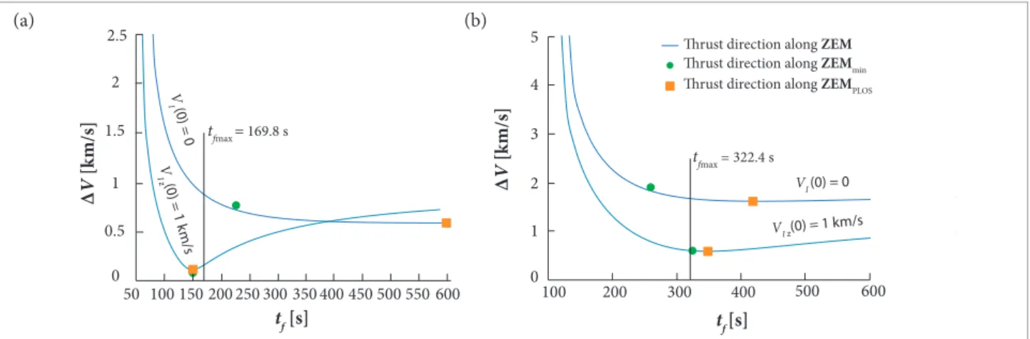
respectively, for their corresponding resulted i nal times. In Fig. 2, the fuel consumption is depicted versus predetermined i nal time for 2 cases of an initial 0 velocity, vI (0) = 0, and a vertical velocity ofvI
z (0) = 1 km/s for a stationary target at rT = [500 0] Tkm.
Also, the minimum fuel consumption is not occurred necessarily
when ZEM
min is utilized; however, it may occur for a special
case. It should be noted that an appropriate i nal time (or time-to-go until intercept) is estimated in practice.
In order to investigate more precisely, the fuel consumption is drawn versus range in Fig. 3 for the 3 mentioned guidance schemes when the interceptor launches from rest. Other initial values and parameters are similar to Fig. 2. As shown in Figs. 2 and 3, the fuel consumption is highly increased using guidance law (Eq. 33) based on ZEM
PLOS. In Fig. 3, the minimum fuel
consumption for the case of thrust direction along ZEM is computed by setting the optimum value, tf*, for intercept time. In other words, tf* is the intercept time for minimum ΔV when the thrust acceleration is imposed along ZEM. h e value of ε
is, here, chosen as 1 m due to numerical errors.
In the next step, the performances of the conceptual guidance laws are compared in Figs. 4a and 4b for a free-falling target at an initial altitude of 100 km, having a minimum required velocity to hit the origin in a l at-Earth model. Initial values and parameters are similar to Fig. 2, except target position. h e target range is taken 100 and 500 km for Figs. 4a and 4b, respectively. A vertical solid line has been drawn for each of Figs. 4a and 4b, showing the maximum possible i nal time (tfmax), i.e. the time of hitting origin (0,0) by the free-falling target. h e region at the right-hand side of this vertical line is not acceptable, because the interception of a free-falling target occurs behind the origin in negative altitudes. h is is an important dif erence between the two cases of stationary and free-falling targets.
According to our analysis for a l at-Earth model, the capture criteria for the conceptual guidance law based on ZEM
PLOS are
highly restricted comparing to the conceptual guidance law based on ZEM, at least, for non-throttleable rockets.
We are now to study the performance of conceptual guidance laws (Eqs. 31, 32, and 40) for a spherical-Earth model in Figs. 5 – 14 against stationary targets. h e interceptor i res
Figure 4. Fuel consumption versus i nal time for interception of a free-falling target in l at-Earth model. (a) initial range = 100 km;
(b) initial range = 500 km.
Figure 2. Fuel consumption versus i nal time for interception
of a stationary target in l at-Earth model.
6
5 5.5
4.5 4 3.5 3 2.5 2
1 1.5
150 350 550 750 950 1,150
tf [s]
∆
V
[k
m/s]
hrust direction along ZEM
hrust direction along ZEMmin hrust direction along ZEMPLO
2.7 km/s
1.8 km/s
4.8 km/s
3.8 km/s
VI(0) = 0
VIZ(0) = 1 k m/s
5 6 7 8
0 9
1 10
2 3 4
0 300 600 900 1,200 1,500
Range [km]
∆
V
[k
m/s]
hrust direction along ZEM (with tf*) hrust direction along ZEMmin
hrust direction along ZEMPLOS
hrust direction along ZEM
hrust direction along ZEMmin hrust direction along ZEMPLOS 2
2.5
550 600 500 0
0.5 1 1.5
50 100 150 200 250 300 350 400 450 tf [s]
∆
V
[k
m/s]
4 5
0 1 2 3
100 200 300 400 500 600
tf [s]
∆
V
[k
m/s]
V
I (0) = 0
V
I z(0) = 1 k
m/s
tfmax = 169.8 s
VI (0) = 0
VI z(0) = 1 km/s
tfmax = 322.4 s
Figure 3. Fuel consumption versus range for interception of
a stationary target in l at-Earth model.
from position rI
0 = [6400 0]
T km with a velocity of 1 km/s
along near vertical horizon (89°) and ath = 50 m/s2. he initial
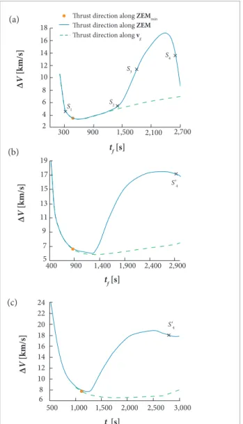
distance of target from the earth center is taken rT = 6,500 km. First, the fuel consumptions of these guidance laws are plotted in Figs. 5a; 5b and 5c for a target at range angles of 10; 40 and 70°, respectively. As seen in the figures, if the thrust direction is applied along the direction of vg, the fuel consumption is considerably reduced for long-range applications. To investigate the trajectory of the interceptor based on ZEM direction, four scenarios with diferent inal times are selected. hese points, namely, S1; S2; S3 and S4 are assigned in Fig. 5a for diferent speciied inal times when the range angle is 10°.
he typical interceptor trajectories of the mentioned scenarios are illustrated in Figs. 6a, 6b, 6c, and 6d for the points S1, S2, S3, and S4, respectively, and compared to interceptor trajectories based on vg direction with the same inal times. he interceptor trajectories based on ZEM and vg are viewed by solid and dashed lines, respectively. he thrust cut-of time, tco, is also observed for each trajectory in the igures. In the case of ZEM-based trajectory, increasing total light time causes an extra revolution of trajectory around the earth center, as shown in Fig. 6d. he maximum limit of total light time to avoid this phenomena is assigned with S4 in Fig. 5a and with S4’ in Figs. 5b and 5c with diferent range angles. he typical interceptor trajectories with inal times larger than that of S4’ in Figs. 5b and 5c, are similar to Fig. 6d for ZEM-based trajectories. Moreover, Fig. 7 shows that the fuel consumption of vg-based guidance law is less sensitive to the estimation of total light time. In this igure, the total light time is considered about the total light time for
12 14 16 18
2 4 6 8 10
S’4
S’4
S3
S4
S2 S1
300 900 1,500 2,100 2,700
tf[s] hrust direction along ZEM
hrust direction along ZEMmin
hrust direction along vg
∆
V
[k
m/s]
∆
V
[k
m/s]
∆
V
[k
m/s]
13 15 17 19
5 7 9 11
14 16 18 20 22 24
6 8 10 12
400 900 1,400 1,900 2,400 2,900
tf[s]
tf[s]
500 1,000 1,500 2,000 2,500 3,000
30
25 35
0 5 10 15 20
0 10 20 30 40 50 60 70
Range angle [deg]
Incr
eas
e in ∆
V
[%]
hrust direction along vg, tf = 0.9 tfmin
hrust direction along ZEM, tf = 0.9 tfmin hrust direction along vg, tf= 1.1 tfmin
hrust direction along ZEM, tf = 1.1 tfmin
T
T I
T I
I
T I
tco
tco tco
tco
tco
tco
tf = 320 s
S1
tf = 1,400 s
tf = 1,800 s
S3
tf = 2,600 s (not to scale)
S2
S4
Figure 5. Fuel consumption versus inal time for interception
of a stationary target in spherical-Earth model. (a) range
angle = 10°; (b) range angle = 40°; (c) range angle = 70°. Figure 7. Increase in ∆V for guidance laws based on vg and ZEM.
Figure 6. Typical interceptor trajectories for initial range
angle = 10° and different values of total light times (solid line: thrust vector along ZEM direction; dashed line: thrust vector along vg direction).
(a) (a)
(c)
(c)
(b)
100 90 110 120
40 50 60 70 80
0 50 100 150 200
t [s]
θth
[d
eg]
θth
[d
eg]
θth
[d
eg]
ath = 50 m/s2
ath = 100 m/s2
64 63 65
58 59 60 61 62
0 20 40 60 80 100 120 140
t [s]
64 63 65
58 59 60 61 62
0 20 40 60 80 100 120 140
t [s]
Figure 8. Thrust angle proiles with respect to the equatorial plane
for interception of a stationary target for minimum energy orbit with initial range angle = 10°. (a) thrust vector along ZEM direction; (b) thrust vector along vg direction; (c) constant vg direction.
minimum ΔV for each guidance scheme, and it is denoted by
t
fmin, which is obtained for each range.
(a)
(c) (b)
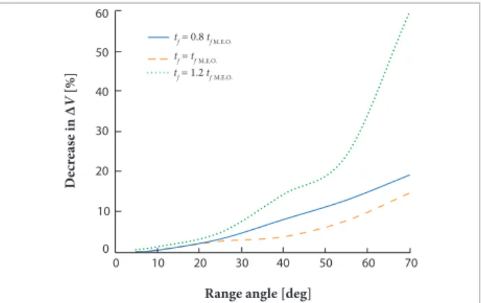
Figure 12. Decrease in ∆V for vg- based guidance with respect to
ZEM-based guidance for minimum and non-minimum energy orbit. 60
50
0 10 20 30 40
0 10 20 30 40 50 60 70
Range angle [deg] tf = 0.8 tfM.E.O.
tf = tfM.E.O.
tf = 1.2 tfM.E.O.
M
ea
n o
f |θ
VZ
| [d
eg]
60
50
0 10 20 30 40
0 10 20 30 40 50 60 70
Range angle [deg]
D
ecr
eas
e in ∆
V
[%]
tf = 0.8 tf M.E.O. tf = tfM.E.O. tf = 1.2 tfM.E.O. 60
50 70 90 80 100
0 10 20 30 40
0 10 20 30 40 50 60 70
Range angle [deg] Max Mean
|θVZ
| [d
eg]
6
5
0 1 2 3 4
0 10 20 30 40 50 60
t [s]
θVZ
[d
eg]
Mean value
Figure 11. Mean of the absolute value of the angle between
vg and ZEM versus range angle for thrust vector along ZEM direction with different total inal times.
Figure 10. Max and mean of the absolute value of the angle
between vg and ZEM versus range angle for thrust vector along ZEM direction (minimum energy orbit).
Figure 9. History of the angle between vg and ZEM for thrust vector
along ZEM direction (minimum energy orbit with a range angle of 10°).
for minimum energy orbit. Other parameters and initial values are similar to Fig. 5. In these igures, θth is the angle of the thrust acceleration with respect to the equatorial plane. As can be seen in these igures, the guidance law based on ZEM has a larger total rotation of the thrust vector than those of the two guidance laws based on vg . Also, it is observed that the rate of change of θth is nearly constant for the two guidance laws based on vg. his property phenomena can be used for implementation of the guidance laws based on vg .
An important question comes from the implementation point of view: what is the typical value of the angle between ZEM and vg? If this value is large enough to overwhelm the control system tracking error and estimation error of required velocity in the presence of target tracking error, the performance study of the guidance law can go ahead for this purpose.
First, the angle between vg andZEM, denoted by θVZ, is depicted in Fig. 9 versus time for an interceptor when its thrust acceleration is applied along ZEM for a range angle of 10°. he maximum and the mean of |θVZ|, ∫o tco |θ
VZ| dt/tco, are observed
by solid and dashed lines, respectively. he maximum and mean
values of |θVZ| are shown in Fig. 10 versus range angle. he inal times in Figs. 9 and 10 are chosen for minimum energy orbit, i.e. minimizing the required velocity. To investigate more precisely, the mean value of |θVZ| is plotted in Fig. 11 versus
range angle for a deviation of ±20%with respect to the inal time of minimum energy orbit. As expected, the values of θVZ are large enough to overcome noisy measurements and control system tracking error for medium-to-super range applications. he efect of this deviation on ∆V can be viewed in Fig. 12 where the comparison is made with respect to the fuel consumption of the ZEM-based guidance law.
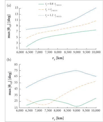
he efect of target altitude is investigated in Fig. 13. First, the fuel consumption is plotted versus target radial position for a range angle of 10° for the minimum energy orbit. As can also be seen in Fig. 5a, there is little diference between the fuel consumptions of vg- and ZEM-based guidance laws. his diference is increased by increasing the range angle. For example, the diference is shown in Fig. 13b for the range angle of 40°. Moreover, the maximum value of the angle between vg andZEM versus target radial position can be viewed in Figs. 14a and 14b for minimum and non-minimum energy orbits,
Figure 14. Max of the absolute value of the angle between vg
and ZEM versus target radial position for thrust vector along ZEM direction. (a) range angle = 10°; (b) range angle = 40°.
Figure 13. Fuel consumption versus target radial position
for interception of a stationary target in spherical-Earth model. (a) range angle = 10°; (b) range angle = 40°.
5.5 5 6.5
6
4.5 4 3.5
3 2.5
6,000 6,500 7,000 7,500 8,000 8,500 9,000 9,500 10,000
rT [km]
6,000 6,500 7,000 7,500 8,000 8,500 9,000 9,500 10,000
rT [km]
∆
V
[k
m/s]
hrust direction along ZEM
Constant vg direction
hrust direction along vg
8 7.5
7 6.5
6 5.5 9.5 10
9 8.5
5
∆
V
[k
m/s]
13 15
11
1 3 5 7 9
6,000 6,500 7,000 7,500 8,000 8,500 9,000 9,500 10,000 6,000 6,500 7,000 7,500 8,000 8,500 9,000 9,500 10,000
rT [km]
rT [km]
max |θ
VZ
| [d
eg]
75 85
65
15 25 35 45 55
max |θ
VZ
| [d
eg]
tf = 0.8 tfM.E.O.
tf = tfM.E.O.
tf = 1.2 tfM.E.O.
(a) (a)
e.g. tf = (1± 0.2)tfM.E.O., respectively, where M.E.O. is the mean energy orbit.
Ater a preliminary study of conceptual guidance laws for lat-Earth model and also stationary targets in spherical-Earth model, we focus on free-falling targets in the case of spherical-Earth model. he interceptor initial position, velocity, and acceleration due to thrust is taken similar to the studied case of spherical-Earth model with stationary targets.
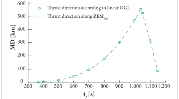
First, the guidance law based on linearized ZEM, Eq. 26, is compared to the guidance based on the direction computed by linear optimal guidance law (Eq. 36) as obtained by Deihoul and Massuomnia (2003). he miss distance and fuel consumption of the two guidance schemes are plotted in Figs. 15 and 16
versus inal time for a target at a range angle of 40°, having the required velocity of minimum energy to hit the initial position of the interceptor. he initial distance of target from the Earth center is taken rT = 6,500 km. hese 2 guidance laws produce nearly the same results; however, the little diferences in the results cannot appear properly in Figs. 15 and 16 because of the
scale of these igures. hese results are obtained by setting an optimized value of tb = 60 s in Eq. 37 for the gain matrixM. his analysis turns out the gain matrix M do not give a signiicant improvement on the performance of the ZEM-based guidance schemes for an initial range angle less than 40°.
To study more precisely, the initial distance of the target from the earth center increases to 7,500 km. First, the value of
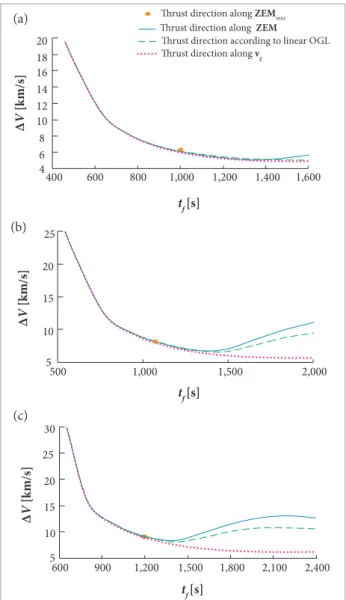
tb is chosen 100 s by the performance analysis based on Fig. 17 for an initial range angle of 90° with 3 diferent values of total inal times. In the next step, the fuel consumptions of four conceptual guidance laws, i.e. guidance laws based on ZEMmin, based on ZEM, based on the direction of linear optimal problem, and based on velocity-to-be-gained are compared together. For this purpose, the fuel consumption is depicted versus inal time in Figs. 18a; 18b and 18c for 3 diferent initial range angles of 60°; 90° and 120°, respectively. he value of tb is optimized for each range angle. Other parameters and initial values are taken as before. For a typical range comparison, the interceptor travels 29.7° (3,301 km) for an initial range angle of 90° (10,002 km) as plotted in Fig. 19 for a total light time of 1,600 s. he thrust direction along the velocity-to-be-gained produces less fuel consumption among the other mentioned guidance laws as shown in the Fig. 18. For short range applications, the angle between ZEM and velocity-to-be-gained is negligible as shown in Fig. 20. he angle between the 2 directions increases by increasing the initial range angle. he efect of matrix gain of M is also increased by increasing the range angle, but for these ranges the direction of the velocity-to-be-gained produces a considerable decrease on fuel consumption. Besides, the estimation error of time-to-go for guidance laws based on velocity-to-be-gained has less sensitivity than that of ZEM-based guidance schemes.
hrust direction according to linear OGL hrust direction along ZEMLin
15
13 17
3 5 7 9 11
300 400 500 600 700 800 900 1,000 1,100 1,200
tf[s]
∆
V
[k
m/s]
300 400 500 600 700 800 900 1,000 1,1001,200
tf [s]
600
500
400
300
200
100
0
MD [k
m]
hrust direction according to linear OGL
hrust direction along ZEMLin
14 13 15 16
8 9 10 11 12
0 100 200 300 400 500
tb [s]
∆
V
[k
m/s]
tf = 2,200s
tf = 1,600 s
tf = 1,400 s
Figure 16. Fuel consumption versus inal time for
interception of a free-falling target in spherical-Earth model (initial range angle = 40°).
Figure 15. Miss distance (MD) versus inal time for
interception of a free-falling target in spherical-Earth model using linearized ZEM relation (initial range angle = 40°).
Figure 17. Fuel consumption versus burnout time for
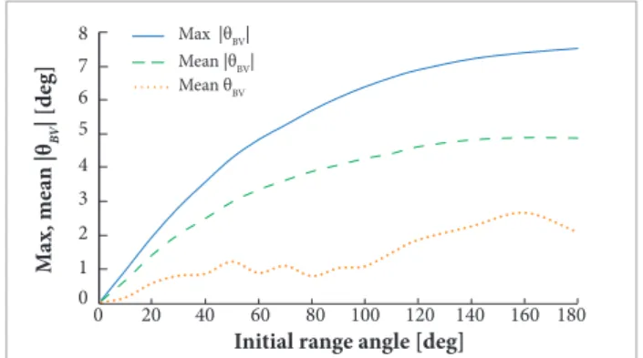
he angle of thrust direction with respect to the equatorial plane is plotted in Fig. 21 versus time for 3 guidance laws. As can be seen, there is a little diference between the velocity-to-be-gained direction and the direction of guidance laws based on constant vg direction. he maximum diference for an initial range angle of 70° is about 5.26°. In addition, the rate of change of thrust direction for guidance laws based on velocity-to-be-gained are very small comparing to that of the guidance laws based on ZEM. To investigate more precisely the diference between the thrust angles under the 2 conceptual guidance laws based on velocity-to-be-gained, θBV, is shown in Fig. 22 in three forms, i.e. max of |θBV|, mean of |θBV|, and mean of
θBV for a minimum energy orbit and a stationary target. Initial values for interceptor and its target are the same as Figs. 5 – 7. As seen in Fig. 22, the mean value of θBV is 1.11° for an initial
Figure 18. Compassion of fuel consumption of four
conceptual guidance laws for interception of a free-falling target in spherical-Earth model. (a) initial range angle = 60°; (b) initial range angle = 90°; (c) initial range angle = 120°.
16 14 20 18
12 10 8 6 4
400 600 800 1,000 1,200 1,400 1,600
tf [s]
∆
V
[k
m/s]
∆
V
[k
m/s]
hrust direction along ZEM
hrust direction along ZEMmin
hrust direction according to linear OGL hrust direction along vg
25
20
15
10
5
500 1,000 1,500 2,000
tf [s]
∆
V
[k
m/s]
tf [s] 30
25
20
15
10
5
600 900 1,200 1,500 1,800 2,100 2,400
Interceptor trajectory (thrust direction along ZEM) Earth surface
Interceptor trajectory (thrust direction along vg) Target trajectory
120
100
0 20 40 60 80
0 10 20 30 40 50 60 70 80 90 100 110 120
Intial range angle [deg]
Max Mean
|θVZ
| [d
eg]
130
110
10 30 50 70 90
0 30 60 90 120 150 180
t [s]
hrust direction along ZEM
hrust direction along vg Constant vg direction
θth
[d
eg]
Figure 19. Interceptor and its target trajectories for initial
range angle of 90° and total light time of 1,600 s.
Figure 20. Maximum and mean of the absolute value of
the angle between vg and ZEM versus initial range angle for interception of a free-falling target (thrust vector along ZEM direction, minimum energy orbit).
Figure 21. Comparison of thrust angle with respect to the
equatorial plane for 3 conceptual guidance laws (initial range angle = 70°; ath = 50 m/s
2).
(a)
(b)
range angle of 70°. heir fuel consumptions are compared in Fig. 23 versus initial range angle for minimum and non-minimum energy orbit. For example, the guidance based on the constant vg direction causes a decrease of 0.32% in fuel consumption for minimum energy orbit with respect to the guidance law based on vg direction for a range angle of 180°. As seen in Fig. 22, below the initial range angle of 10.3°, max |θBV| is less than 1°. However, improving the performance of a guidance law is always of interest by a modiied formulation without any additional hardware or extra cost. Fortunately, several iterative and approximate methods are available in literature to calculate the required velocity and Q-matrix for Lambert’s problem.
For space missions, Sokkappa (1966) developed a near optimal guidance in closed-loop for throttleable spacecrat assuming constant Q-matrix; however, the Q-matrix was updated for onboard computation. Our simulation results show that the maximum diference between the thrust angles of Sokkappa’s
solution and guidance based on constant vg direction is less than 0.5° when the initial range angle is less than 180° (the initial values and parameters are similar to Fig. 22). In addition, Sokkappa compared his optimal solution with the guidance law based on constant vg direction for a case of injection from an earth orbit of 100 nautical miles to pass through an inertial point of 180,000 nautical miles. he guidance law based on constant vg direction produces ∆V = 3,328.6 m/s, whereas Sokkappa’s solution has a 34.2 m/s decrease in ∆V. Also, the performance of guidance law based on constant vg direction and numerical optimal solution was compared by Circi (2004) for a satellite launch vehicle. he optimum solution has a decrease of 39 kg for a payload mass of 1,734 kg under the guidance law based on constant vg direction for a perigee of 150 km.
It is worth noting that the guidance laws based on velocity-to-be-gained are applicable provided that a required velocity can be deined. For example, a required velocity cannot be deined for a ixed-inal-time problem when inal position and velocity vectors are both constrained. he impact angle of the conceptual guidance schemes is not considered in this investigation. It may be accomplished using appropriate choice of inal time.
CONCLUSIONS
his study suggests the efective thrust direction of an exoatmospheric interceptor for interception of short-to-super range moving targets with inal position constraint. This has accomplished using a comprehensive study on conceptual guidance laws with stationary, moving, and free-falling targets. he irst class of guidance law is based on ZEM. hree guidance schemes are considered in the irst class, regarding to 2 deinitions of ZEM and the component of ZEM perpendicular to line-of-sight. he capture criteria of the guidance scheme based on the perpendicular component of ZEM are highly restricted for non-throttleable rockets. he second class of conceptual guidance laws are based on linearized formulation, i.e. linearized ZEM and linear optimal control theory for throttleable rockets when its computed thrust direction is applied to non-throttleable rockets. he third class of guidance laws is based on the generalized required velocity and generalized velocity-to-be-gained. Two guidance schemes are considered in the third class. In the irst scheme, the thrust acceleration is applied along the velocity-to-be-gained vector,
6 7 8
5
0 1 2 3 4
0 20 40 60 80 100 120 140 160 180
Initial range angle [deg] Max |θBV|
Mean |θBV| Mean θBV
M
ax, me
a
n |θ
BV
| [d
eg]
0.5
0.0 0.1 0.2 0.3 0.4
0 20 40 60 80 100 120 140 160 180
Initial range angle [deg]
D
ecr
eas
e in ∆
V
[%]
tf = 0.7 tfM.E.O.
tf = 0.9 tfM.E.O. tf = 0.8 tfM.E.O.
tf = tfM.E.O.
tf = 1.2 tfM.E.O. tf = 1.1 tfM.E.O.
tf = 1.3 tfM.E.O.
Figure 22. Maximum and mean of the absolute value,
and mean value of the angle between the thrust direction along vg and constant vg direction versus range angle for interception of a stationary target for minimum energy orbit.
Figure 23. The percentage decrease in ∆V for the guidance
law based on constant vg direction with respect to vg
whereas the second scheme tries to avoid the rotation of the velocity-to-be-gained in an inertial space.
he suggested direction of thrust acceleration is along the generalized velocity-to-be-gained, deined based on the generalized required velocity for interception of moving targets. For short-range application, the same results have been achieved when the thrust acceleration applied in the direction of ZEM or in the direction of the generalized velocity-to-be-gained. Increasing the range angle, the diference in performance is appeared. For long-range interception, the suggested thrust direction requires less amount of fuel rather than conceptual guidance laws based on ZEM or linearized formulations. he guidance performance is not improved as expected using a ZEM vector multiplied by a gain matrix to deviate the thrust direction from ZEM vector, as obtained in linearized optimal solutions.
If the intercept time is chosen a bit larger than the minimum energy orbit due to tactical consideration, e.g. salvo iring, adjustment of impact angle, etc., the suggested direction will have a signiicant fuel savings rather than guidance laws
based on ZEM. Moreover, the performance of the suggested conceptual guidance law has less sensitive to the estimation error of inal time. he guidance scheme based on constant velocity-to-be-gained direction may improve negligibly the fuel performance of the interceptor in the presence of noise for suborbital interception. Finally, the optimal solution does not give a better performance when the target position and velocity are contaminated by noise for suborbital interception such as a ballistic target; however, it improves the performance for a satellite launch vehicle and possibly for interception of orbital targets.
AUTHOR’S CONTRIBUTION
Mohamed-abadi MD performed the numerical solutions and prepared the igures. he idea, assumptions, classiications, and framework belong to Jalali-Naini SH, who wrote the manuscript. Both authors discussed the results and commented on the manuscript.
REFERENCES
Ahn J, Bang J, Lee SI (2015) Acceleration of zero-revolution Lambert’s algorithms using table-based initialization. J Guid Control Dynam 38(2):335-342. doi: 10.2514/1.G000764
Arora N, Russell RP, Strange NJ, Ottesen D (2015) Partial derivatives of the solution to the Lambert boundary value problem. J Guid Control Dynam 38(9):1563-1572. doi: 10.2514/1. G001030
Battin RH (1999) An introduction to the mathematics and methods of astrodynamics. Revised edition. Reston: American Institute of Aeronautics and Astronautics.
Bryson AE, Ho YC (1975) Applied optimal control. New York: Hemisphere.
Chen FL, Xiao Y, Chen W (2010) Guidance based on velocity-to-be-gained surface for super-range exoatmospheric intercept. Acta Aeronautica et Astronautica Sinica 31(2):342-349. In Chinese.
Circi C (2004) Hybrid methods and Q-guidance for rocket performance optimization. Proc IME G J Aero Eng 218(5):353-359. doi: 10.1243/0954410042467040
Deihoul AR (2003) Anti ballistic optimal midcourse guidance law (PhD thesis). Tehran: Sharif University of Technology. In Persian.
Deihoul AR, Massoumnia MA (2003) A near optimal midcourse guidance law based on spherical gravity. Scientia Iranica 10(4):436-442.
Feng C, Yelun X, Wanchun C (2009) Guidance based on zero effort
miss for super-range exoatmospheric intercept. Acta Aeronautica et Astronautica Sinica 30(9):1583-1589. In Chinese.
Jalali-Naini SH (2004) Modern explicit guidance law for high-order dynamics. J Guid Control Dynam 27(5):918-922. doi: 10.2514/1.5902
Jalali-Naini SH (2008) Generalization of zero-effort miss equations in atmospheric guidance laws with application to midcourse flight (PhD thesis). Tehran: Sharif University of Technology. In Persian.
Jalali-Naini SH, Pourtakdoust SH (2005) Modern midcourse guidance laws in the endoatmosphere. Proceedings of the AIAA Guidance, Navigation and Control Conference and Exhibit; San Francisco, USA.
Jalali-Naini SH, Pourtakdoust SH (2007) A unified approach to intercept guidance laws. Proceedings of the 6th Iranian Aerospace Society Conference; Tehran, Iran.
Li LG, Jing WX, Gao CS (2013) Design of midcourse trajectory for tactical ballistic missile intercept on the basis of zero effort miss. App Mech Mater 397-400:536-545. doi: 10.4028/www. scientific.net/AMM. 397-400.536
Martin FH (1965) Closed-loop near-optimum steering for a class of space missions (PhD thesis). Cambridge: Massachusetts Institute of Technology.
Massoumnia MA (1995) Optimal midcourse guidance law for fixed-interval propulsive maneuvers. J Guid Control Dynam 18(3):465-470. doi: 10.2514/3.21410
Mohammad-abadi MD, Jalali-Naini SH (2016) Approximate solution of zero-effort-miss under gravitational acceleration inversely proportional to the cubic distance. Modares Mech Eng 16(4):135-144. In Persian.
Newman B (1996) Strategic intercept midcourse guidance using modified zero effort miss steering. J Guid Control Dynam 19(1):107-112. doi: 10.2514/3.21586
Rusnak I, Meir L (1991) Modern guidance law for high-order autopilot. J Guid Control Dynam 14(5):1056-1058. doi: 10.2514/3.20749
Sokkappa BG (1966) On optimal steering to achieve required velocity. Proceedings of the 16th International Astronautical Congress; Athens, Greece.