Diogo Luís Barradas Alves
Licenciado em Engenharia Electrotécnica e de Computadores
Implementation of a Private Cloud
Dissertação para obtenção do Grau de Mestre em
Engenharia Electrotécnica e de Computadores
Implementation of a Private Cloud
Copyright © Diogo Luís Barradas Alves, Faculty of Sciences and Technology, NOVA Uni-versity of Lisbon.
A c k n o w l e d g e m e n t s
In the first section I would like to take the opportunity to express my gratitude to everyone I had the pleasure of meeting during the elaboration of my thesis and helped me reach my goals.
First and foremost I would like to thank my advisor, Professor Pedro Amaral, for the possibility of developing and building a cloud infrastructure, as well for promoting my fascination for telecommunications, networking and distributed systems.
I would like to express my extreme gratitude to Kátia Ludmila for believing in me and giving me a chance to teach at 4sfera and also to everyone at the academy, it was without a doubt one of the best and most enriching experiences of my life and for that I am ever grateful, not only the vote of confidence but also for receiving me into their family and threating me as one of their own.
To everyone I’ve met over the years they’ll all have a special place in me, wherever I’ve worked, studied or had fun I’ll carry forever with me the experiences we lived. To all the people I’ve met in college from day one Vanda Valentim, Liliana Sequeira, Ricardo Peres, and all of those that came after Tiago Silva, Diogo Tristão, Ricardo Rodrigues, Carlos Simão, Fabiana Paradinha, Vitor Rodrigues and Bruno Semedo thank you for making these years phenomenal. As I could not forget to my closest friends Teresa Rodrigues, Filipe Vale, Ricardo Silva, Pedro de Brito, Diogo Sardinha, Filipe Rodrigues, Pedro Rebelo, Tiago Cardoso, Miguel Ferreira and Tiago Cristovão thank you for everything you’ve done for me. To everyone mentioned above a sincere thank you as I am fortunate for having such a rich and wonderful foundation.
A b s t r a c t
The exponential growth of hardware requirements coupled with online services develop-ment costs have brought the need to create dynamic and resilient systems with networks able to handle high-density traffic.
One of the emerging paradigms to achieve this is called Cloud Computing it pro-poses the creation of an elastic and modular computing architecture that allows dynamic allocation of hardware and network resources in order to meet the needs of applications.
The creation of a Private Cloud based on the OpenStack platform implements this idea. This solution decentralizes the institution resources making it possible to aggre-gate resources that are physically spread across several areas of the globe and allows an optimization of computing and network resources.
With this in mind, in this thesis a private cloud system was implemented that is capable of elastically leasing and releasing computing resources, allows the creation of public and private networks that connect computation instances and the launch of virtual machines that instantiate servers and services, and also isolate projects within the same system.
The system expansion should start with the addition of extra nodes and the modern-ization of the existing ones, this expansion will also lead to the emergence of network problems which can be surpassed with the integration of Software Defined Network controllers.
R e s u m o
O crescimento exponencial dos requisitos de hardware aliado aos custos de desen-volvimento de serviços online trouxeram a necessidade de criar sistemas dinâmicos e resilientes dotados de redes capazes de lidar com alta densidade de tráfego.
Um dos paradigmas emergentes denomina-seCloud Computing, permite a implemen-tação de um sistema elástico e modular de compuimplemen-tação permitindo a alocação de recursos de hardware e rede dinamicamente, de maneira a responder às necessidades das aplica-ções web.
A implementação de umaCloudprivada com base na plataformaOpenStack imple-menta esta ideia. Esta solução descentraliza os recursos da instituição na medida em que é possivel agregar hardware que está distribuido geograficamente e permite também uma otimização dos recursos computacionais e de rede.
Com isto em mente, a presente tese implementa um sistema decloudprivada capaz de elasticamente reservar e libertar recursos de computação, criar redes públicas e privadas que permite a comunicação entre instancias de computação, lançar máquinas virtuais que instanciam servidores e serviços e também isolar projetos dentro do mesmo sistema. A expansão do sistema deve começar com a adição de nós e com a modernização dos nós já implementados, com esta expansão é esperado o surgimento de problemas de rede que podem ser superados com a integração de controladoresSoftware Defined Network.
C o n t e n t s
List of Figures xv
List of Tables xvii
Acronyms xix
1 Introduction 1
1.1 Background & Motivation . . . 1
1.2 Challenges . . . 2
1.3 Thesis Outline . . . 3
2 State-of-the-Art 5 2.1 Cloud Computing . . . 5
2.1.1 Service Models . . . 6
2.1.2 Deployment Models . . . 6
2.2 Available Platforms . . . 8
2.2.1 Eucalyptus . . . 8
2.2.2 OpenNebula . . . 9
2.2.3 OpenStack . . . 9
2.2.4 Comparative Analysis . . . 10
2.2.5 Final Verdict . . . 11
2.3 OpenStack . . . 11
2.3.1 OpenStack Compute Nova . . . 11
2.3.2 OpenStack Networking Neutron . . . 12
2.3.3 OpenStack Image Service Glance . . . 13
2.3.4 OpenStack Identity Keystone . . . 14
2.3.5 OpenStack Dashboard Horizon . . . 14
2.3.6 OpenStack Telemetry Ceilometer . . . 14
2.3.7 OpenStack Object Storage Swift . . . 15
2.3.8 OpenStack Block Storage Cinder . . . 16
2.4 Software Defined Networks . . . 16
2.4.1 OpenDaylight . . . 17
C O N T E N T S
2.4.3 Open Network Operating System (ONOS) . . . 19
2.5 SDN Integration with OpenStack . . . 21
3 Architecture 23 3.1 OpenStack Logical Architecture Overview . . . 23
3.1.1 OpenStack Compute Overview . . . 25
3.1.2 OpenStack Network Overview . . . 27
3.1.3 OpenStack Identity Overview . . . 29
3.1.4 OpenStack Object Storage Overview . . . 31
3.1.5 OpenStack Block Storage Overview . . . 33
3.1.6 OpenStack Image Overview . . . 34
3.2 Openstack Physical Architecture Overview . . . 35
3.2.1 Common Structures / Services . . . 38
3.2.2 Hardware Specifications . . . 39
4 SDN Architecture 41 4.1 Logical SDN Architecture . . . 41
4.2 Physical SDN Architecture . . . 45
4.3 SDN Controller Comparative Analysis . . . 45
5 Results and Validation 49 5.1 Resource Optimization . . . 49
5.2 Instance Deployment and Access . . . 50
5.3 Use Cases . . . 53
5.4 Discussion of Results . . . 54
6 Conclusion and Future Work 55 6.1 Conclusion . . . 55
6.2 Future Work . . . 55
L i s t o f F i g u r e s
2.1 OpenDaylight Architecture [32]. . . 18
2.2 FloodLight Architecture [33]. . . 19
2.3 ONOS Architecture [35]. . . 21
3.1 OpenStack Logical Architecture Overview [16]. . . 24
3.2 OpenStack Compute Architecture. . . 27
3.3 OpenStack Network Arquitecture. . . 29
3.4 OpenStack Identity Concept Relation. . . 30
3.5 OpenStack Object Storage Architecture. . . 32
3.6 OpenStack Volume Storage Architecture. . . 34
3.7 OpenStack Image Architecture. . . 34
3.8 Implemented basic node deployment. . . 35
3.9 OpenStack suggested basic node deployment. [16] . . . 36
3.10 Cloud Network Layout. . . 37
3.11 Network Traffic [20]. . . . 38
4.1 OpenStack Logical SDN Architecture. . . 42
4.2 SDN Controller Integration into OpenStack [39]. . . 42
4.3 OpenDaylight to OpenStack communication. . . 43
4.4 FloodLight to OpenStack communication. . . 44
4.5 ONOS to OpenStack communication [41]. . . 44
4.6 OpenStack Physical SDN Architecture. . . 45
5.1 Resource usage with two instances running. . . 50
5.2 Image launch configuration. . . 51
5.3 VCN access to an Ubuntu Server instance deployment. . . 51
5.4 SSH access to an Ubuntu Server instance running. . . 52
L i s t o f Ta b l e s
3.1 OpenStack Services. . . 25
3.2 Compute Service Component Overview. . . 25
3.3 Network Service Component Overview. . . 28
3.4 Keystone Service Concepts. . . 30
3.5 Object Storage Service Component Overview. . . 31
3.6 Block Storage Service Component Overview. . . 33
3.7 OpenStack Components [16]. . . 35
3.8 OpenStack Hardware Specifications. [16] . . . 39
3.9 Used Hardware Specifications. . . 40
5.1 Resource usage with two instances running. . . 50
A c r o n y m s
ACL Access Control List.
API Aplication Programming Interface.
AWS Amazon Web Services.
CC Cluster Controller.
CLC Cloud Controller.
DHCP Dynamic Host Configuration Protocol.
ext-br External Bridge.
FL Floodlight.
GUI Graphic User Interface.
HTTP HyperText Transfer Protocol.
IaaS Infrastructure as a Service.
IP Internet Protocol.
IT Information Technology.
JSON JavaScript Object Notation.
L2 Layer Two.
L3 Layer Three.
LDAP Lightweight Directory Access Protocol.
MAC Media Access Control.
ML2 Modular Layer 2.
NAT Network Address Translator.
AC R O N Y M S
NIC Network Interface Controller.
NIST National Institute of Standards and Technology.
ODL OpenDaylight.
ONF Open Network Foundation.
ONOS Open Network Operating System.
OS Operative System.
OSGi Open Service Gateway Initiative.
PaaS Platform as a Service.
PC Personal Computer.
PNI Physical Network Interface.
QoS Quality of Service.
SaaS Software as a Service.
SAL Service Abstraction Layer.
SC Storage Controller.
SDN Software-Defined Networking.
SPICE Simulated Program with Integrated Circuits Emphasis.
SSH Secure Shell.
TCP Transmission Control Protocol.
VLAN Virtual Local Area Network.
VM Virtual Machine.
VNC Virtual Network Computing.
VNI Virtual Network Interface.
C
h
a
p
t
e
r
1
I n t r o d u c t i o n
1.1 Background & Motivation
Computing as we know has evolved into a new paradigm,"Cloud Computing". In cloud computing data and computation tasks are fulfilled remotely in a "cloud" providing the delivery of hardware, system software and applications as a service over the Internet.
Cloud Computing is a fast-growing technology, that supplies the Information Tech-nology (IT) industry demands for stable software and dynamic hardware. It enables large scale data processing and also allows universal access, ease of management and a lower starting investment since this solution can be deployed on a pay-per-use base.
In a conventional processing environment there is a need to scale up the resources (e.g. adding more RAM, disk space or CPU power) to satisfy demand but in a cloud environment the resources are scaled out, due to its elastic nature. This allows virtual instances to share workload between them, it is possible to replicate instances on demand. With the increase of the cloud complexity new problems such as network complexity can rise. To solve this dilemmas new network technology and tools are used. One of the most popular approaches is Software-Defined Networking (SDN), a model which enables a better control over the network layout, resulting in a better overall performance of the system.
In the academic IT environment there is a need for large data processing, simulation and service providing. These tasks can take weeks to run or be very hardware intensive. But when given access to a larger pool of computing resources it can be done in a few hours or days. While it is not conceivable to build a super computer the cloud enables the possibility of grouping several computers and combine their resources.
C H A P T E R 1 . I N T R O D U C T I O N
resources can be allocated and released on demand thus removing the need for provision-ing in early stages of a project.
Cloud Computing can also allow teachers and students alike to use its resources in the lab or in lectures, for instance professors can create virtual environments with the needed software for a project and every time a student needs to work on such project it is possible to access that instance and work on it, retrieving the results later.
A cloud platform can really greatly impact an educational institution by supplying on-line learning applications and environments, it supports mobile learning, scalability also reduces the costs of hardware and proprietary software making it a all around solution as a educational platform. The network access control and management has a huge impact not only on the users experience but also on the cloud performance so, network services should also be taken into consideration.
My motivation for this thesis was to be able to create a a private cloud by integrating the existing hardware in order to attain all the benefits of a cloud computing infrastruc-ture in the department.
1.2 Challenges
The implementation of a cloud in an educational environment provides some interesting challenges, such as:
• Limited resources, what are the minimum resources to implement a private cloud into a scholar environment?
• Flexibility to change the underlying network, is it possible to build a private cloud and run a SDN Controller in this scenario, what would be the advantages of doing so?
• Use of open-source software. What are the best open-source solution available in the market and how would this approach affect the standard architecture?
For the first challenge, we discovered that when it comes to cloud computing services the hardware requirements are minor, so it is possible to build a simple cloud that can manage simple mundane tasks. The hardware requirements only have to scale to accom-modate the workload requirements, so in a scholar environment it is possible to build a prototype cloud that can host a limited amount of instances, and then increase the hardware further to accommodate higher workloads.
1 . 3 . T H E S I S O U T L I N E
As for the last challenge, a comparative analysis was made to outline the available open-source solutions and how these solutions would affect the implemented
architec-ture.
This thesis goal is to build a cloud system using open-source software and the hard-ware available in the department. The primary objective is to use the hardhard-ware resources available and prepare the system for expansion, so it can deal with higher workloads and be more suitable to be used as a research and development tool of the teaching and student core.
Using OpenStack it was possible to implement a cloud architecture that had as an underlying hardware three HP Proliant servers that power the cloud one of the server is running as a cloud controller and the other two run as cloud compute nodes. The controller node is responsible for the synchronization of the services and communica-tion between them and the compute node is responsible for the life cycle of the virtual instances that they are running. The open source software also allows the control and management of users/projects, network and orchestration.
The implemented model should be able to manage users, user access to projects, virtual networks and instances. It is also capable of creating and deleting private virtual networks on top of the physical network, deploy instances onto the virtual network, create virtual routers that establish connections between private and public virtual networks and also private to private virtual networks. Finally it is capable of running several Operative System (OS) desktop and server instances that can communicate in between them and the Internet, the architecture should also be able to load balance instances amongst similar computing nodes.
With large expansion in mind it is expected that network complexity and congestion problems arise, so a set of SDN solutions were outlined and taken into consideration how these solutions would affect the implemented architecture, and what would be the
changes to be made in hardware and software configuration.
After the architecture was implemented several workload and access tests were made to validate the implemented system although only in a closed environment as it was impossible to test in a true production environment due to the lack of capable hardware.
1.3 Thesis Outline
The first chapter of this thesis explains the core concepts of the technology used, the mo-tivation behind the development of the system, the challenges faced, and goals reached.
Chapter 2 depicts all technology integrated in this work as well as a comparative analysis between several open source solutions still present in today’s market.
Chapter 3 approaches the physical implementation of the project, how the different
modules interact and how they work independently from each other.
C H A P T E R 1 . I N T R O D U C T I O N
Chapter 5 aims to validate the overall performance of the system, the optimization of the hardware resources and a discussion of the results.
C
h
a
p
t
e
r
2
S t a t e - o f - t h e -A rt
Cloud computing is the latest trend in IT and it has reached the point where it is no longer an auxiliary utility as they are a cornerstone to our routine. Users are able to access these services from anywhere without any perception of where the service is or how it is delivered making it possible for software to be used by thousands of people at the same time [1].
2.1 Cloud Computing
The industry struggled several years with a true definition of cloud computation. The term appears for the first time in computer network diagrams and uses the cloud symbol to represent the Internet, the final definition appeared by the hand of the National Insti-tute of Standards and Technology (NIST) that defined cloud computing [2] “a model for enabling ubiquitous, convenient, on-demand network access to a shared pool of configurable computing resources that can be rapidly provisioned and released with minimal management effort or service provider interaction.”.
The cloud should be composed by five characteristics:On-demand self-service,users can allocate server resources and network storage automatically without the provider interaction;Broad network access,the services are accessed over the network with all sorts of client platforms thus promoting heterogeneity;Resource pooling,the resources are pooled dynamically using a multi-tenant model with the resources location being shadowed by a layer of abstraction;Rapid elasticity,the physical system resources can be scaled inwards or outwards on demand giving the user a sense of unlimited provisioning;
Measured service, the system itself optimizes the use of resources this way resource usage can be controlled and reported giving the provider and the consumer transparency.
C H A P T E R 2 . S TAT E - O F -T H E -A R T
to this reality: it must be user-centric,once you are connected to the cloud everything you create from documents to images and applications belongs to you; it is powerful,
the agglomeration of thousands of CPUs creates an unimaginable amount of computing power unable to be reached with a single Personal Computer (PC) and since all the data is stored in the cloud users can retrieve it from several machines this way not creating bottlenecks;it is intelligent,due to a high amount of data the access to it has to be done in an effective way; it’s programmable,data must be replicated to protect its integrity
so that if one computer goes offline the data it contains has to exist as a copy on another
computer in the cloud [3].
2.1.1 Service Models
Every deployment of a cloud has three service models in them, these provide different
levels of abstraction:
Software as a Service (SaaS): this is the highest layer of abstraction the user has no control over the network, operating system or hardware he is leasing, the application is accessible by the client device (ie. Smartphone, computer or tablet) or a program interface allowing the user to control only specific application settings [2, 4].
Platform as a Service (PaaS): the PaaS allows users to develop applications with tools supported by the provider without worrying about the underlying infrastructure and just like in the SaaS model there is no control or access to the lower layers of complexity henceforth the user has no control the network, physical layers or the architecture [5].
Infrastructure as a Service (IaaS): this is where consumer gain access to computer re-sources such as processing power, memory and storage so they can set up and run their applications, this model contrasts with the others since it is the lowest layer of abstraction giving this way access to the hidden infrastructure [2].
Cloud computing suplies a simplified software installation, maintenance and central-ized control over the software that is running, so that this way the end-users can access the cloud services “anytime” and from “anywhere” just as long as they have a reasonably amount of bandwidth [6].
2.1.2 Deployment Models
The NIST also refers four possible deployment models with different characteristics to
serve a different group of users, the models are the following [2]:
2 . 1 . C L O U D C O M P U T I N G
out of the equation. These clouds are managed by a third party organization that guarantees the Quality of Service (QoS) as long as the users have enough bandwidth to cope with the cloud traffic. Some of the biggest advantages of this model are continuous uptime, on-demand scalability and the inexpensive setupbut, since it is a public cloud, it has drawbacks indata security and privacy. This is due to the fact that the location of where the data is stored or backed is unknown so there is a possibility of being accessed by unauthorized users. The biggest beneficiaries of this deployment model are smaller organizations that outgrew their infrastructures and use a public cloud to store information and services while upgrading their infrastructures or simply just migrate into a public cloud infrastructure [7].
Private Cloud: On a private cloud the access is restricted to an organization or a third party that has been given access. The main objective of this model is not to supply cloud services to the general public but to have the organization data spread around several points of interest. This cloud is hosted by the same company that uses it therefore, it provides more security than a public cloud. A private cloud enables the use of data center unused resources. These can be sold as services or computing resources. This way a private cloud allows companies to have a greater control and generate profit with their computational resources. The power of this power comes from the fact that it can maximize the hardware power using virtualization, reducing costs and complexity. Since the most important asset a company is its information, trusting this to an outside entity that can be vulnerable to cyber attacks is a major problem that led todays industry to shift to private clouds [2, 7].
Community Cloud: A community cloud aggregates the sustainability from Green Com-puting, the distributed resource provision from Grid ComCom-puting, the control from Digital Ecosystems and the self-management from Autonomic Computing. It com-petes with vendor clouds and makes use of its user resources to form a cloud with the nodes taking the roles of consumer, producer and coordinator. This concept removes the dependence of cloud suppliers. This cloud is a social structure due to the community taking ownership over the cloud. As the nodes act in self-interest having one control center would be unpractical, so it is nuclear to reward the nodes in order to redirect their computing power to the cloud and not themselves. In a cloud community each user would have an identity that supplies a service or web-site to the community. Since this cloud model isn’t owned by a company it is not attached to that company lifespan, therefore it ends up being more resilient and robust to failures and immune to system cascading failures. The biggest challenge faced by this model is the QoS since it is a heterogeneous system the nodes will most likely need to reach critical mass to satisfy all the QoS requirement from different
systems [8].
C H A P T E R 2 . S TAT E - O F -T H E -A R T
intermediate stage of a company lifecycle. When a corporation tries to supply its services to the public, it can expand their data center and host a public cloud, bring-ing several benefits such has: Optimal utilization,since the data centers can be at times in an idle state and have only a small fraction of their resources being used, hybrid clouds increase the servers utility by making some of their resources public;
Data center consolidation: since the cloud has expanded to a hybrid model the servers will consolidate their instances, reducing the operation costs;Risk transfer:
with a hybrid cloud model the network workload management shifts from the oper-ator to the vendor which is prepared to deal with higher workloads;Availability:a data center needs redundancy, backups and geographic dissemination this can be a very expensive to maintain so in a hybrid cloud environment the public counterpart can scale up and take the private cloud side if the company cloud goes down due to a failure or an attack [9].
2.2 Available Platforms
There are several open-source cloud platforms that enable the customization of the cloud and provide flexibility. These have features that enhance scalability, portability, flexibility and on-demand services. The three most used cloud platforms are Eucaliptus, OpenNeb-ula and OpenStack so the following section will discuss the advantages and drawbacks of these three platforms [10, 11, 12].
2.2.1 Eucalyptus
Eucalyptus [10, 12] is an acronym for Elastic Utility Computing Architecture for Linking Your Program To an Useful System. It is used to deploy private and hybrid cloud solutions and it is developed by the company Eucalyptus Systems. This cloud platform implements an IaaS model and it became the first open source software compatible with Amazon Web Service Aplication Programming Interface (API). This platform has a sizable collection of virtualization technologies this enables the cloud to incorporate resources without modifying the base configuration. The Eucaliptus cloud is armed with five components:
Cloud Controller (CLC),the entry point for the administrators, project managers and users, this module also helps with the management of the virtual resources;Cluster Con-troller (CC), this controller runs on a machine and is responsible for the management of the VM network so the controller must be in the same subnet has the nodes;Storage Controller (SC),this controller provides the block-level network storage; andNode Con-troller (NC),the NC is installed in all the computers and is used to monitor VM activities, like execution and termination of instances.
The main benefit of this platform is its efficiency, organization and agility but it also
2 . 2 . AVA I L A B L E P L AT F O R M S
2.2.2 OpenNebula
OpenNebula [11, 13] was designed to help companies build a simple, cost-effective,
reli-able and open enterprise cloud on the existing IT infrastructure. It provides flexible tools that orchestrate storage, network, and virtualization technologies. It has a flexible design and it is modular to allow integration with different storage and network infrastructure
and hypervisor technologies. This platform is mainly used as a virtualization tool, but it also has support to hybrid cloud besides private cloud, thus combining local infrastruc-ture with public cloud-based strucinfrastruc-tures enabling highly scalable hosting environments. The platform orchestrates storage, manages network, enables virtualization, resource monitoring and cloud security as it also deploys multi-tier services, namely computing clusters that work as VMs on distributed structures, combining resources of the data centers with the remote cloud.
OpenNebula [13] has three main layers:the driver layer,this is responsible for start-ing and shuttstart-ing down VM, allocatstart-ing storage for VMs and monitorstart-ing the operational status of the physical resources by communicating directly with the underlying operat-ing system, thus it works as an abstract service to shadow the underlyoperat-ing infrastructure;
the core layer,manages the VMs full life cycle, including setting up the virtual network dynamically so that allocated dynamic Internet Protocol (IP) address for the VMs do not overlap and managing VMs storage allocation;the tool layer,enables the communication with users and provides a control point to manage VM through. A scheduler manages the functionality provided by the core layer.
OpenNebula toolkit main features for integration are management, scalability, secu-rity and account. OpenNebula also claims to have interoperability and portability giving the providers a choice of several cloud interfaces [12].
2.2.3 OpenStack
OpenStack [12] is the quickest evolving open source platform for cloud computing, emerg-ing in 2010 by the hand of NASA and Rackspace with the mergemerg-ing of Rackspace "Cloud Files" platform and NASA "Nebula" platform. This platform has been deployed by global enterprise customers whose processes and data stores are measured in petabytes the data therefore cannot be store the traditional way, it is stored in a distributed storage static data systems such as images of virtual machines, files, backups and archives in addi-tion. OpenStack provides greater scalability, redundancy and durability, objects and files are stored on multiple disks scattered in the data center, providing replication and data integrity.
C H A P T E R 2 . S TAT E - O F -T H E -A R T
redirect traffic to another compute nodes, which can be useful during maintenance or in
case of failure. Users can create their own networks, control traffic and connect machines
to one or more virtual networks.
2.2.4 Comparative Analysis
The comparative analysis of the aforementioned platforms will be based on several factors such as: released date, community support, the underlying architecture, cloud implemen-tation, source code language, compatible hypervisors, Virtual Machine (VM) migration possibility, etc. [10, 15].
The Eucalyptus and OpenNebula were established in 2008 with the first being the re-sult of a research project of the university of California computer science department and OpenNebula was funded by an European grant and the help of the companies Research In Motion, Telefonia and China Mobile. OpenStack only appeared in the summer of 2010 by the joint project of NASA and RackSpace. As of today the OpenStack platform is the one who gathers more support since it is backed by the giants of IT (around 850 companies) of which we can find names like HP, Dell, IBM, RackSpace, NASA, Cisco, AT&T which take part in the project. OpenStack community integrates around 7000 contributors over 87 countries [10, 11].
Eucaplytus architecture is hierarchically built with the Cloud Controller being on top and the Node Controller on the bottom of the hierarchy this way requiring at least two servers, the OpenNebula has a centralized architecture with three modules in its core while the OpenStack setup is based in four modules Nova, Neutron, Glance and Swift displayed in a classical node architecture having a front end and group of compute nodes running VMs in the back, all the nodes are required to have a physical network to connect them to the front end [10, 15].
All the three platforms are open source but while Eucalyptus and OpenNebula only deploy the private and hybrid cloud models and OpenStack also implements the public cloud model [15].
Based on the source code languages OpenStack is more restricted as it only supports Phyton while Eucalyptus also supports Java and C and OpenNebula supports Java, Ruby and C++ [15].
The three platforms support Linux and several of its distributions while Eucalyptus is the only one that is strictly Windows based [11, 15].
OpenNebula uses as a database management system MySQL, while Eucalyptus uses PostgreSQL to store metadata and user information and the OpenStack Nova module supports any database that is supported by SQL-Alquemy [10].
2 . 3 . O P E N S TAC K
Eucalyptus does not allow virtual machine migration while OpenNebula and Open-Stack have that capability [10].
2.2.5 Final Verdict
Based on the analysis done in the previous subsection and on the following literature [10, 11, 12, 15], there is no need to use proprietary cloud platforms when the open source platforms have so much support and capabilities, mainly due to the large communities to back them up. At first sight the platforms stand all at the same level and only differ
in purpose or in community support, with OpenStack development focus being, the creation of an open source software that allows researchers and administrators to deploy IaaS and to manage virtual machines on top of the available computing resources, it seems this platform provides the best support for this thesis final objective which is the implementation of a private cloud, this coupled with the enormous community backing it up and an astonishing development rhythm makes it the perfect tool to implement the cloud.
2.3 OpenStack
The OpenStack [16] project enables the implementation of massively scalable and fea-tured rich public, private and hybrid clouds using a set of interrelated services to provide an IaaS solution with each service offering an API to enable an easier integration.
The first release of OpenStack was on October 21, 2010 [17] and almost six years and twelve versions later the OpenStack Foundation is getting ready to release on October 6, 2016 the Newton version.
A standard deployment of an OpenStack [16] cloud integrate core modules which supply a wide range of services, these core modules are: OpenStack Compute Nova,
OpenStack NetworkingNeutron,OpenStack Image ServiceGlance,OpenStack Identity
Keystoneand OpenStack DashboardHorizon.On top of the previously mentioned mod-ules, a cloud implementation may also include the OpenStack Object StorageSwiftor OpenStack Block StorageCinder,Openstack TelemetryCeilometerand Openstack Or-chrestrationHeat.
2.3.1 OpenStack Compute Nova
The OpenStack Nova [18] has a modular architecture composed of six components: nova-api, queue, nova-db, nova-conductor, nova-scheduler and nova-compute these compo-nents interact with each other to manage virtual machines.
C H A P T E R 2 . S TAT E - O F -T H E -A R T
and facilitator for interactions between nova-compute and the database, it eliminates the direct access of nova-compute to the cloud database thus eliminating security problems. The nova-scheduler is responsible for VM handling, it accepts requests for virtual ma-chine instances from the queue and using the scheduling algorithms assigns that VM to a compute server host to run it. Nova-compute is a daemon responsible for the life-cycle of virtual machine instances by using the hypervisors APIs supported by the virtualization technology [18].
Nova-compute receives user requests with instructions to performed from the queue, it executes system commands according to the received request and also updates the database if needed by communicating with it via the nova-conductor service. In a more in depth scenario we can say that the compute infrastructure in Nova works on top of the physical layer managing the resources available for virtualization, this infrastructure is elastic and can scale with the variation of resources. The compute infrastructure is divided in zones for the purpose of providing physical isolation granting therefore fault tolerance, within each zone exists several physical nodes that have the nova-compute service running, based on scheduling algorithms defined in nova-scheduler VMs are provisioned to these hosts. Within each host there is also a hypervisor and middleware that are used when a VM is assigned [18].
2.3.2 OpenStack Networking Neutron
OpenStack Networking or namely Neutron [19] is an API driven service that is used to de-fine, manage networking and addressing it in the cloud itself, enabling the control of the network configuration. With Neutron it is possible to define, separate or merge networks on demand. Neutron is an abstraction layer as it does not implement any networking functions, this module only provides methods, agents and plugins, that can be used. The Neutron project provides a plugin mechanism that enables different networking
imple-mentation and consistent high-level API for abstraction, there are also API extensions that enable control over security, compliance, monitoring and troubleshooting functions.
Neutron mimics the physical implementation using virtualized subnets and ports for abstraction, it works similarly to the layer two segment, ports and subnets are assigned to network objects. The subnet abstraction layer consists a block of IP addresses, a gateway, a list of Domain Name Systems (DNS) and a list of host routes. This generates a large subnet address pool that Neutron works on top by assigning IPs to VMs. The port abstraction is a virtual point for each VM as the port receives an IP and Media Access Control (MAC) address from the pool of subnets, if needed users can request specific addresses from the subnet pool via an API call [19].
2 . 3 . O P E N S TAC K
via Linux IP stack and ip tables allowing users to create routers that connect the Layer Two (L2) networks and Modular Layer 2 (ML2) agent that establishes a framework for Neutron plugins this agent will eventually replace the monolithic plugins associated with all the L2 agents [19].
OpenStack networking [19] uses three additional tools in its implementation which are network namespaces, Floating IP addresses and network security groups, the names-paces prevents the overlapping of subnets on the physical layer and tenants, this is im-plemented using Linux namespaces preventing duplicate IP addresses in the logical and physical networks used by the virtual machines. Floating IPs are public IPs that can be dynamically given to VM instances, these can also have a private IP addresses. In Neu-tron the L3 agent provides the Network Address Translator (NAT) functionality assigning floating IP addressed to the VM instances. Neutron implements the network security via Security Groups which allows users to specify the type of traffic and direction it can flow
therefore in Neutron each port is associated to a security group and IP tables are used to implement the security groups.
2.3.3 OpenStack Image Service Glance
The Glance service[16] is central to IaaS. It receives requests for disk or server images and metadata definitions from users or Nova components. It also supports the storage of server and disk images in several repository including Cinder. OpenStack Image runs periodic processes supporting caching, also information consistency and availability are ensured through the replication services.
The OpenStack image service is composed by the following components: glance-api which is responsible for accepting image API calls for discovery and, retrieval and storage of images; glance-registry stores, processes and retrieves metadata about images, this metadata includes items information such as size and type of image, this registry is a private service as it is only meant to be used by the OpenStack Image service it should not be exposed to other users or services; the database is used to store image metadata, the database most used deployments are the MySQL and SQLite databases; Storage repository for image files there are several repository types available such has Object Storage, RA-DOS block devices, HyperText Transfer Protocol (HTTP) and Amazon S3 must be taken into consideration that some repositories are read-only usage; Metadata definition service it is a common API used by administrators, services and user to define custom made meta-data, it can be used on different types of resources like images, artifacts, volumes, flavors
C H A P T E R 2 . S TAT E - O F -T H E -A R T
2.3.4 OpenStack Identity Keystone
Keystone[16] is the central authentication, authorization and identity service mecha-nism for all OpenStack services components and users, it supports various forms of au-thentication this includes username and password credentials, token-based systems and public/private key pairs-style logins it also includes integration with existing directory services such has Lightweight Directory Access Protocol (LDAP).
Although keystone supports several authentication and authorization forms, it relies mainly on tokens so when an user interacts with a service he is required to possess a token as an instance of his identity and roles, the user can have an unscoped token however it will not be usable in a typical daily operation like creating a virtual machine or uploading one machine image. When the user requests a scoped token keystone checks for his assignments to see if he is allowed to access that domain or project. Tokens are structured as JavaScript Object Notation (JSON) objects and include parameter like: user identification (id,name), authentication method, expiration date, service catalog and project or domain to which the token is scoped [20].
The identity service is also a major actor in the authentication and authorization of workflow due to its catalog lists of all the services deployed by the cloud, it handles the authentication through endpoints, an endpoint is a network address where a service is lis-tening for requests so each service, for instance Nova or Glance, has at least one assigned endpoint. OpenStack Identity uses tenants to group or isolate resources it then issues tokens to authenticated users after that the endpoints can validate the token before al-lowing user access, additionally the Keystone service responds to service requests, places messages in queue, grants access tokens and update the state database [19].
2.3.5 OpenStack Dashboard Horizon
Managing the OpenStack environment through a command-line interface gives the ad-ministrator complete control over the cloud environment, but having an usable Graphic User Interface (GUI) to manage the environments and instances makes the process easier. OpenStack Dashboard known as Horizon [21] provides this GUI, a web service that runs from an Apache installation, using Python’s Web Service Gateway Interface and Django for a quick development web framework.
2.3.6 OpenStack Telemetry Ceilometer
2 . 3 . O P E N S TAC K
the list of meters continuously grows within the project it is possible to use the data col-lected by Telemetry to more than billing, for instance it is possible to trigger the auto-scale feature in the Orchrestration service [16]. The Telemetry Data Collection [16] service pro-vides several functions such has: efficiently pools metering data related to OpenStack
services; collection of events and metering data by monitoring notifications sent from services; publication of collect data to various targets including data stores and message queues.
2.3.7 OpenStack Object Storage Swift
OpenStack Swift[23] is a highly available, distributed and consistent object storage that can operate in standalone mode or integrated with the rest of the OpenStack cloud com-puting platform. It is used to store a great amount of data efficiently, safely and cheaply
using a scalable redundant storage system. Swift manages data as objects opposed to the conventional file systems that manage data using file hierarchy and block storage, each object includes the data itself, a variable amount of metadata and a globally unique identifier. With its well defined RESTful API, users can upload or download objects to and from the Swift storage.
Inside Swift, objects are organized into containers similarly to directories in a file system except that the Swift containers cannot be nested. An user is associated with a Swift account and can have multiple containers associated with that account, in order to manage user accounts, user containers and objects inside a container, Swift uses an Account Server, a Container Server and Object Servers correspondingly if an user account requests for an object inside a container (either for uploading or downloading), the Ac-count Server looks for the acAc-count first in its database and finds associated containers with the account it then checks for the container database to find whether the requested object exists in the specified container and finally the Object Server looks into the object databases to find retrieval information about the object, in order to retrieve an object the Proxy Server needs to know which of the Object Servers are storing the object, and what is the path of the object in the local file system of that server [23].
Once an object is stored in Swift, the access control is determined by Swift Access Control List (ACL). Swift has different levels of ACL, Account level ACL allows users to
C H A P T E R 2 . S TAT E - O F -T H E -A R T
2.3.8 OpenStack Block Storage Cinder
The Block Storage [24] service enables the management of virtualized block storage de-vices on several storage back-end systems, the cinder-scheduler deamon is reponsible for scheduling virtual volumes to physical storage hosts.
The default scheduling algorithm in Cinder is called Available Capacity and it is based on a filtering/weighting procedure the scheduler works in three steps at first when a new volume request comes in the scheduler first filters out the hosts which have insufficient
resources like capacity or too much workload to meet the needs of the request then the scheduler calculates a weight for each of the remaining hosts based on the available capacity and sorts them based on this weight in an increasing order, the lightest will be on top, the host which has the least weight is chosen as the best candidate to serve the new request [24].
2.4 Software Defined Networks
Computer networks as they are known are divided in three layers: data, control and management layers. The first one (data layer) consists of routers, switches, bridges, etc. these are responsible for the forwarding of data, the second dimension (control layer) represents the protocols that service the forwarding tables of the data plane elements and for the management layer, it includes the software services that are used to audit and configure the control functionality. The aforementioned structure is highly decentralized which was considered a very important characteristic of the Internet since it guaranteed network resilience, a crucial design goal, however this led to a very complex and static architecture and is the main reason why traditional computer networks are stern and complicated to manage and control this lead to a vertically-integrated industry where is hard to innovate [25].
SDN came to be at the hands of the Open Network Foundation (ONF) which works to develop, standardize and commercialize SDN. The ONF defines SDN as it follows:
"Software-Defined Networking is an emerging network architecture where network control is decoupled from forwarding and is directly programmable"[26]. In this context SDN unique-ness resides in its ability to provide programmability by decoupling the control and data planes since it supplies simpler network devices in the case of active networking. As such, network intelligence can be removed from the switching devices and placed on the network controllers making the switching devices externally controlled by software thus having no on-board intelligence. This decoupling of the control and data layers offers a
greater freedom for external software, it enables the control and help define the behavior of the network [27].
2 . 4 . S O F T WA R E D E F I N E D N E T WO R K S
agreement[28, 29]. Virtualization simplifies the deployment of systems since there is no cabling or setting up of the Network Interface Controller (NIC), neither the need to place the system in a rack, the only thing needed to spawn a virtual system is to launch an instance from an image and to allocate the hardware resources, traditional networking has a “closed architecture which is proprietary and vertical integrated”[30], this lack of flexibility disables the ability to define high level network policies to the entire network and addi this to the frequent changes in the network conditions, it makes the control of networking traffic in data centers one of the most challenging tasks due to the enormous
amount of servers, applications and networking devices which is what SDN excels at.
Amongst the available open-source projects available that are integrated with cloud networks we can find OpenDaylight (ODL), Open Network Operating System (ONOS) and Floodlight (FL) which will be described and studied in depth in the following subsec-tion [19, 30].
2.4.1 OpenDaylight
OpenDaylight (ODL) is an open source software SDN controller coded in Java, embed with a modular, pluggable and flexible controller architecture. The ODL project was established under Linux Foundation with the objective to help the dissemination and adoption of SDN thus creating an underlying foundation for NFV. The software sup-ports a bidirectional northbound REST-based API that originated from the Open Service Gateway Initiative (OSGi) Model, which provides a framework for the modularization of applications into small bundles for the northbound API. The southbound interface supports multiple control and data plane protocols, also plugins, these modules are dy-namically linked into a Service Abstraction Layer (SAL) so the SAL is a representation of all the modules that are written northbound. These layers are responsible to fulfill the requests from services independently of the underlying protocol used between the controller and the devices[31, 32].
C H A P T E R 2 . S TAT E - O F -T H E -A R T
the supported southbound plugins and protocols are: OpenFlow, OVSDB, Netconf, LISP, BGP, PCEP and SNMP; as for the fifth and last layer it is the physical and virtual network devices layer, it interacts with the plugins and southbound protocols, it can be plug-in enabled (OpenFlow-enabled) or can be supported via a southbound protocol in addition to the logical architecture, ODL also supports multi-tenancy which allows the networks to be split for tenants and have dedicated controllers and module functions [19].
Figure 2.1: OpenDaylight Architecture [32].
2.4.2 FloodLight
Floodlight (FL) is more than an OpenFlow controller is also a collection of applications as we can see in Figure 2.2 that are built on top of the controller. This controller is able to manage and control an OpenFlow network, while the applications that run embed on top of the controller are able to solve the needs over the network. The Java module applications run from origin on the controller and each app is mapped in the REST API enabling application calls, information retrieving and service invocation despite the languages or protocols inherent to the calling application [33].
As the majority of the SDN controllers FL was designed as an extremely concurrent system, that can achieve high throughput since it has a multi-threaded design that ex-plores the parallelism of multi-core computer architectures, it also has its own north-bound API that abstracts the inner details and behavior of the control and data planes [25].
In a data center context a FL controller provides a comprehensive view of the VM activities, it is capable of listening to OpenFlow-based Transmission Control Protocol (TCP) connections from each of its switches and then it is able to manage the traffic so
2 . 4 . S O F T WA R E D E F I N E D N E T WO R K S
software can estimate the best possible route and according to the a load factor and network traffic it can create a flow that leads the packets from the source to the destination,
so in this way FL offers a high level of granularity in network management and also a
central view of the network traffic. These features enable the network to be flexible thus
enhance its performance [30].
Figure 2.2: FloodLight Architecture [33].
2.4.3 Open Network Operating System (ONOS)
Open Network Operating System is an open source SDN network operating system (Fig-ure 2.3) that feat(Fig-ures the high availability, scale-out and performance networks demand. ONOS uses northbound abstraction and APIs that enable the user to develop applications and a southbound abstraction and interfaces to allow the control of OpenFlow-ready and legacy devices, so in short ONOS enables: carrier grade features to the control plane; Web style agility; the migration of existing networks to white boxes; and the lowering of service provider CapEx and OpEx [34].
C H A P T E R 2 . S TAT E - O F -T H E -A R T
availability and performance features that complete the SDN control platform. ONOS differs from a SDN controller because it is responsible for the following features: it is
able to manage a finite amount of resources on behalf of the consumer, and doing so, it ensures that none of the consumers aren’t starved and are handled fairly; ONOS isolates and protects network operating system users from each other since each user only has access to a set of resources, it also multiplexes between multiple apps and devices, ONOS also virtualizes some or all the resources in order to allow consumers to have their own virtual instantiation of the OS; it provides useful abstraction to enable users to consume services and resources that are managed by the OS without having to understand all of the underlying complexity; the system provides security from the external world to the users OS; and finally it supplies useful services that remove the need for rebuilding the same services. In short controllers are too limited in scope as they may not provide the necessary services or protection when compared with ONOS [34].
The ONO System architecture[34] foundations are High Availabilty, Scale-out Capa-bilities and Performance and this is achieved with the following features:
• Distributed Core it provides scalability, high availability and performance thus, bringing carrier grade features to the SDN control plane. ONOS can run as a cluster which brings a huge amount of agility to the SDN control plane;
• Northbound abstraction/APIsthat include network graph and application intents to ease the development of control, management and configuration services, adding once again agility to the control plane;
• Southbound abstraction/APIs that enable pluggable southbound protocols that enable the control of both OpenFlow and Legacy devices, it isolates ONOS core from the total of different devices and protocols. This feature is the main enabler
of the migration from legacy devices to OpenFlow-based white boxes;
2 . 5 . S D N I N T E G R AT I O N W I T H O P E N S TAC K
Figure 2.3: ONOS Architecture [35].
2.5 SDN Integration with OpenStack
C
h
a
p
t
e
r
3
A r c h i t e c t u r e
As previously discussed in Chapter 2, the cloud computing concept has been evolving over the years, mainly fueled by the IT industry necessities for a better network access to a shared pool of computing resources, with the capacity to be rapidly allocated and leased with minimal management.
With this in mind, the cloud computing system (OpenStack) described in this chapter aims to provide the core features of a cloud computing architecture, On-demand self-service that allows the user to lease computing resources automatically, broad network access which enables the access of services over the Internet independently of the client platform, rapid elasticity that enables the physical resources to scale inwards or outwards on demand, these are just some of the prime characteristics of this system.
This architecture was implemented using the OpenStack software which is one of the quickest evolving open source platform that implements the cloud computing paradigm, being deployed globally it has been tried and tested amongst all the giants of the telecom-munication world. This platform provides the necessary scalability, redundancy and durability required in our environment.
OpenStack, as the name suggests, is an open source (hence Open) cloud system (Stack) that controls computing resources such as compute, storage and network assets with the help of a dashboard which enables the user to provision resources through a web interface, this software aims to implement a simple modular system that provides mass scalability.
3.1 OpenStack Logical Architecture Overview
Figure 3.1 depicts an overview of the services and relations they construct in the logical architecture.
C H A P T E R 3 . A R C H I T E C T U R E
Figure 3.1: OpenStack Logical Architecture Overview [16].
way, each service plays its role in the coordination of the whole system, in order to provide the capabilities specified above (Figure 3.1). As for the services themselves - Object Stor-age (Swift), Identity (Keystone), Compute (Nova), Networking (Neutron), Block StorStor-age (Cinder) and the Image Service (Glance) -, they are the core services implemented with the addition of the Dashboard (Horizon) service. There is also a total of twelve optional services that complement an array of tools to the architecture, such as the Telemetry service (Ceilometer) or the Orchestration service (Heat), where the first enables the me-tering of the system for benchmarking and scalability and the second makes it possible to orchestrate multiple cloud applications using the native HOT templates or Amazon Web Services (AWS) CloudFormation templates.
The current architecture runs only the six services as they were mandatory, plus the dashboard service as it is a quality of life service, since it enables an easier understanding and operability of the system.
3 . 1 . O P E N S TAC K L O G I CA L A R C H I T E C T U R E OV E RV I E W
Table 3.1: OpenStack Services.
Service Project Name Description
General Purpose
Dashboard Horizon Provides a web-based interface that enables the in-teraction in between the user and the OpenStack services.
Compute Nova It is responsible for spawning and decommission of virtual machines, henceforth it controls the life-cycle of VMs.
Networking Neutron This service manages the network and enable con-nectivity for other OpenStack services. It also sup-ports a symbiosis with other network technologies.
Storage
Object Storage Swift Stores and retrieves arbitrary unstructured, it is highly fault tolerant due to data replication across several drivers.
Block Storage Cinder Enables persistent block storage for instances, has a pluggable driver architecture for creation and management of storage devices.
Shared Services
Identity Service Keystone Responsible for the authentication and authoriza-tion of the other OpenStack Services.
Image Service Glance It manages the VM disk images, this service is used by compute during instance provisioning.
To further the understanding of the logical architecture, the following sections will explain the core functionalities and workflow of the service modules described above.
3.1.1 OpenStack Compute Overview
As OpenStack itself the Compute service is also modular. Therefore, it is divided in several services and daemons that cause OpenStack Compute to play a major role in an IaaS system. This module consists of the components in Table 3.2.
Table 3.2: Compute Service Component Overview.
Component Name Description
Services
C H A P T E R 3 . A R C H I T E C T U R E
nova-compute It’s a worker daemon that is responsible for the creation and termination of instances using the hypervisor APIs. (ie. libvirt for KVM and QEMU).
nova-scheduler Responsible for taking instance requests from the queue and assigning them to compute server hosts.
Modules
nova-conductor Responsible for the mediation of the interactions between the nova-compute service and the database.
nova-cert It is a server daemon that is used to generate certificates for the EC2 API.
Daemons
nova-console Worker daemon responsible for the creation and termina-tion of VM.
nova-novncproxy Enables proxy access to running instances via Virtual Net-work Computing (VNC) connection. Supports browser-based novnc clients.
nova-spicehtml5proxy Enables proxy access to running instance via Simulated Pro-gram with Integrated Circuits Emphasis (SPICE) connec-tion. Supports browser-based HTML5 client.
nova-xvpvncproxy Enables proxy access to running instance via a VNC connec-tion. Supports the OpenStack-specific java client.
Backend
Message Queue The central exchange point of messages between daemons and services.
Database Responsible for the storage of build-time and run-time states of the cloud such as, Available instance types, In-stances in use, Available networks and Projects.
The aforementioned components fall into four categories that fully describe the ser-vice architecture.
TheAPI Serveris the heart of the cloud framework this API enables storage, network control, management of the hypervisors. The API endpoints of the server are HTTP web services responsible for authentication, authorization and control functions using the API interfaces models. It is compatible with multiple existing tool sets which prevent vendor lock in.
3 . 1 . O P E N S TAC K L O G I CA L A R C H I T E C T U R E OV E RV I E W
process information is added, removed and searched for into the database as necessary.
Compute Workersare responsible for the lifecycle of the computing instances on the host machines - they can run, delete and reboot instances; they can also attach or detach storage volumes to an instance and show the console output of that instance.
Finally, there is theNetwork Controllerwhich is responsible for the management of network resources. It receives commands through the message queue from the API server and it is able to allocate IP addresses, configure Virtual Local Area Network (VLAN) for projects and configure networks for compute nodes.
Figure 3.2: OpenStack Compute Architecture.
As we can see in Figure 3.2 and from the explanation made above, the Compute service makes use of the nova-scheduler service to choose the best fitting host to deploy an instance, this service (nova-scheduler) interacts with other components through the message queue or the database repository to schedule the tasks. A total of two services can process tasks from the queue, nova-compute and nova-conductor, and after they have terminated the task they proceed to send a message into the queue that is picked up by the scheduler and sent to the nova-api.
3.1.2 OpenStack Network Overview
C H A P T E R 3 . A R C H I T E C T U R E
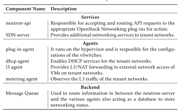
Table 3.3: Network Service Component Overview.
Component Name Description
Services
neutron-api Responsible for accepting and routing API requests to the appropriate OpenStack Networking plug-ins for action. SDN server Provides additional networking services to tenant networks.
Agents
plug-in agent It runs on the hypervisor and is resposible for the configu-rations of the vSwitches.
dhcp agent Enables DHCP services for the tenant networks.
l3 agent Provides L3/NAT forwarding to external network access of VMs on tenant networks.
metering agent Observes the L3 traffic of the tenant networks.
Backend
Message Queue Used to route information in between the neutron-server and the various agents also acting as a database to store networking states.
OpenStack networking is responsible for the Virtual Network Interface (VNI) and the access layer of the Physical Network Interface (PNI). This service makes it possible for tenants to create virtual networks topologies with embedded services like firewalls, load balancers and virtual private networks. It works as an abstraction layer for networks this way enabling sub networking and router creation thus mimicking all the functionalities of the physical counterpart.
The network service always creates an external network which is not just a virtual network but a slice of a physical external network; this way the services can be accessed by external users. In addition to external networks, neutron also has one or more internal networks; these are software defined networks that connect directly to the VMs.
In order for VMs to access outside networks and vice versa, routers have to be placed in between the networks and each router needs to have one gateway connected to the “Internet” and at least one interface connected to the internal network.
It is also possible to allocate IP addresses of external networks to a port on the internal network. These are called public IPs, and associate the external IP to a VMs port. This allows external entities to access the VMs.
Figure 3.3 depicts how the Neutron components communicate with each other. This communication is mainly done using remote process calls in between the native agents of the system, it uses REST communication when using the SDN service and SQL for all the accesses to the database.
3 . 1 . O P E N S TAC K L O G I CA L A R C H I T E C T U R E OV E RV I E W
Figure 3.3: OpenStack Network Arquitecture.
into the message queue that is then picked up by the neutron-server and relayed to the requester, this usually being the compute service or the GUI.
Both the SDN service and the plugin agent work as a proxy for other SDN controllers that the user might want to implement in order to enhance the control and management of the network. This integration will be approached in Chapter 4.
3.1.3 OpenStack Identity Overview
OpenStack Keystone is the single point of integration for authentication, authorization and service cataloging, it is used by other services as a common unified API, so due to this, Keystone is the only service that interacts with all the other services.
When a OpenStack service receives a request from an user the service checks with Keystone if this user has a valid token in case of a positive result the service then proceeds to fulfill the request.
In the core of this service we find three types of components:
• Server, a centralized server that as the ability to authenticate and provide authoriza-tion using a RESTful interface;
• Drivers or service backend - which are integrated with the centralized server - en-able the access to information that is stored in repositories external to OpenStack such as SQL databses or LDAP servers;
• Modules, whose main function is to intercept service requests, extract user creden-tials and transmit them to the centralized server for authorization.
C H A P T E R 3 . A R C H I T E C T U R E
Table 3.4: Keystone Service Concepts.
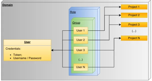
Concept Description
Authentication The process of confirming the identity of an user.
Credentials Data that confirms the identity of an user. Can be the name and password or an authentication token.
Domain It is a collection of projects and users that define adminis-trative boundaries for managing entities.
Groups Collection of users that are owned by a domain.
Project A container that groups or isolates resources and identity objects.
Role Personality with a defined set of user rights and privileges enabling them to perform a specific set of operations. Token An alpha-numeric string that enables access to the
Open-Stack API and resources.
User Digital representation of a person, system or service that needs validation by the identity service.
The highest separation entity is the Domain. In each domain there are Roles, Groups and Projects and inside each group we can find one or several users which can have a different role in the same group and also have access to the same or different projects.
Associated with each user there are credentials that can be a Token or an username and password of that user. These relations are described in the following figure (Figure 3.4).
Figure 3.4: OpenStack Identity Concept Relation.
As it was seen, keystone cornerstone concepts for authentication and authorization are based from the common credential system, they present the credentials to the server which enables them to access the information of a specific group/groups.
3 . 1 . O P E N S TAC K L O G I CA L A R C H I T E C T U R E OV E RV I E W
the first time the user makes a request its credentials consist of their username and password, the credentials are validated and henceforth it is possible to issue a token. From this point on the user can present the token whenever authentication is necessary. It is important to underline that this token has a finite duration and can be revoked at any time.
To contextualize how Keystone controls access we can take the cloud administrator role as an example, this user is able to list all the instances running in the cloud, also change any instance characteristics and resources allocated to them whereas a normal user can only check the instances in their current group, the resource quotas, cores being used, disk space and all other resources associated with the project it belongs to.
3.1.4 OpenStack Object Storage Overview
Object Storage makes it possible for users and applications to store and retrieve objects through a REST API. These objects, which are agglomerates of data, are stored hierarchi-cally and offer three types of access: anonymous read-only , ACL defined and temporary.
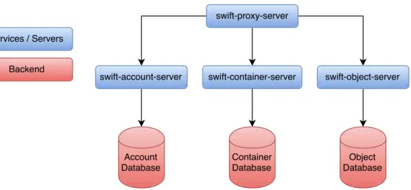
Swift is composed of components in the Table 3.5 and its organization is as displayed in Figure 3.5.
Table 3.5: Object Storage Service Component Overview.
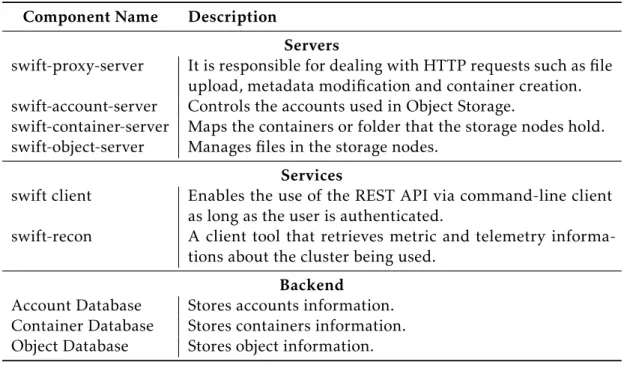
Component Name Description
Servers
swift-proxy-server It is responsible for dealing with HTTP requests such as file upload, metadata modification and container creation. swift-account-server Controls the accounts used in Object Storage.
swift-container-server Maps the containers or folder that the storage nodes hold. swift-object-server Manages files in the storage nodes.
Services
swift client Enables the use of the REST API via command-line client as long as the user is authenticated.
swift-recon A client tool that retrieves metric and telemetry informa-tions about the cluster being used.
Backend
Account Database Stores accounts information. Container Database Stores containers information. Object Database Stores object information.
![Figure 2.1: OpenDaylight Architecture [32].](https://thumb-eu.123doks.com/thumbv2/123dok_br/16581223.738548/38.892.193.748.326.636/figure-opendaylight-architecture.webp)
![Figure 2.2: FloodLight Architecture [33].](https://thumb-eu.123doks.com/thumbv2/123dok_br/16581223.738548/39.892.274.575.298.777/figure-floodlight-architecture.webp)
![Figure 2.3: ONOS Architecture [35].](https://thumb-eu.123doks.com/thumbv2/123dok_br/16581223.738548/41.892.164.684.178.469/figure-onos-architecture.webp)
![Figure 3.1: OpenStack Logical Architecture Overview [16].](https://thumb-eu.123doks.com/thumbv2/123dok_br/16581223.738548/44.892.162.778.151.485/figure-openstack-logical-architecture-overview.webp)