Master in Structural Engineering
Bond behavior and durability of CFRP-to-steel
bonded joints under cyclic loading and
freeze-thaw and salt fog
Dissertation for obtaining the Doctor degree in Civil Engineering Specialty Structures
Adviser: Manuel Américo de Jesus Gonçalves da Silva, Retired Full Professor, Universidade Nova de Lisboa Co-adviser: Carlos Manuel Chastre Rodrigues,
Associate Professor, Universidade Nova de Lisboa Co-adviser: Hugo Emanuel Charrinho da Costa Biscaia,
Researcher, Universidade Nova de Lisboa
Examination Committee
Chairman : Prof. Doutor Jorge Joaquim Pamies Teixeira Examiners: Prof. Doutor Luís Filipe Pereira Juvandes
Prof. Doutor José Manuel de Sena Cruz
Co-examiners: Prof. Doutor Manuel Américo de Jesus Gonçalves da Silva Prof. Doutor João Carlos Gomes Rocha de Almeida
Master in Structural Engineering
Bond behavior and durability of CFRP-to-steel
bonded joints under cyclic loading and
freeze-thaw and salt fog
Dissertation for obtaining the Doctor degree in Civil Engineering Specialty Structures
Adviser:
Manuel Américo de Jesus Gonçalves da Silva,
Retired Full Professor, Universidade Nova de Lisboa
Co-adviser:
Carlos Manuel Chastre Rodrigues,
Associate Professor, Universidade Nova de Lisboa
Co-adviser:
Hugo Emanuel Charrinho da Costa Biscaia,
Researcher, Universidade Nova de Lisboa
Chairman of the
Examination Committee: Prof. Doutor Jorge Joaquim Pamies Teixeira Examiners: Prof. Doutor Luís Filipe Pereira Juvandes
Prof. Doutor José Manuel de Sena Cruz
Co-examiners: Prof. Doutor Manuel Américo de Jesus Gonçalves da Silva Prof. Doutor João Carlos Gomes Rocha de Almeida
Bond behavior and durability of CFRP-to-steel bonded joints under cyclic loading and freeze-thaw and salt fog
Copyright © Yongming Yang, Faculdade de Ciências e Tecnologia, Universidade Nova de Lisboa. A Faculdade de Ciências e Tecnologia e a Universidade Nova de Lisboa têm o direito, perpétuo e sem limites geográficos, de arquivar e publicar esta tese através de exemplares impressos reproduzidos em papel ou de forma digital, ou por qualquer outro meio conhecido ou que venha a ser inventado, e de divulgar através de repositórios científicos e de admitir a sua cópia e distribuição com objectivos educacionais ou de investigação, não comerciais, desde que seja dado crédito ao autor e editor.
Acknowledgements
This work has been conducted during the years 2015 and 2018 at the department of Civil engineering at Faculdade de Ciências e Tecnologia, Universidade Nova de Lisboa, Portugal. At the moment, after finishing the Ph.D. thesis, I wish to express my sincere gratitude to whom without their help during those three years, the thesis is not possible.
Firstly and also foremost, I would like to thank my advisor, Prof. Manuel A G Silva, for giving me the opportunity to join his team, for his patience and for his invaluable inputs to all the aspects on living and studying during those years. I also like to acknowledge my co-advisor, Prof. Carlos Chastre, for his meaningful suggestion on experiment methods design, and for his very helpful comments on the manuscript of the publications. Furthermore, I give my sincere thanks and gratitude to another co-advisor, Prof. Hugo Biscaia, for his valuable and indispensable topic discussion every time, for his pursuit of perfection, for his help to the improvements of the publications writing.
I also would like to thank Prof. Guijun Xian of Harbin Institute of Technology, China, for providing the HIT CFRP laminates to support my Ph.D. work.
I also thank the technicians, Eng. Victor Silva, Mr. Gaspar and Mr. Jorge at the structures laboratory of the department of Civil engineering.
Finally, my deepest gratitude to my parents and sister for their continuous support and encouragements throughout these years.
Abstract
There are many structural members of metallic bridges, namely girders and trusses, requiring rehabilitation and strengthening in a large number of countries. The utilization of polymers reinforced with carbon fibers (CFRP) has been considered of great potential for that purpose and many laboratorial tests have been made in the past 30 years to study the behavior of structural members strengthened with CFRP, based on which structural solutions have been designed and built. Despite that, more research is necessary to obtain data on the mechanical response and durability of those composite materials and structures, as well as on the CFRP/steel joints, to improve design procedures and define more suitable strengthening methodologies.
One of the topics of the thesis is the study of the bond behavior of CFRP/steel joints under mechanical or thermal loading. In a first phase, tests of double-strap joints, with several different bonded lengths were subjected to monotonic loading and a simplified method was developed to estimate the responses and compare with the experimental results. Following that phase, pseudo-cyclic and pseudo-cyclic tests were made to examine the capacity of the joints for those types of loading. The damage developed in the interface was analyzed in a way that allowed the calculation of the dissipated energy and related it to the slip between the CFRP strips and the steel plates.
The durability of the bonded CFRP/steel joints was also studied. The joints as well as adhesive coupons, separately, were exposed to accelerated aging imposed by (i) temperature cycles between -20ºC and +20ºC with testing of effects at selected stages (1,000h, 2,500h, 3,500h, 5,000h and 10,000h), and (ii) salt fog cycles lasting for 5,000h. Both monotonic and cyclic tests were made to evaluate the deterioration caused by aging and different mechanisms were identified. Stresses due to resistance to free thermal expansion and due to galvanic corrosion were also addressed.
Analytical solutions based on local bond laws, either bilinear or tri-linear, were used to estimate the debonding of the CFRP laminates from steel. It was also confirmed that the capacity of the joint is associated with the initiation of damage in the adhesive caused by steel corrosion. A “loading threshold” was detected approximately equal to 50% of the ultimate monotonic loading capacity of the joints, below which cyclic loading does not damage the CFRP/steel integrity. Experimental results showed that the normalized slip at the interface (S/Sult) and the normalized dissipated energy, local and global (wd/Gf and Ed/Et, respectively), may be inter-related both for reference, unaged samples, and aged samples. Moisture is a critical factor in temperature cycles around 0ºC, called freeze-thaw for simplicity, while temperature effects alone for cycles between -20ºC and +20ºC were negligible. Galvanic corrosion between CFRP and steel is generated by the accumulation of corrosion products in the joints, creating electric bridges that lead to deterioration of the CFRP laminates. Local corrosion of steel causes stress concentrations that may lead to brittle failure under monotonic or cyclic loading.
Resumo
Em todo o mundo existem muitos elementos estruturais em pontes metálicas, especialmente vigas e treliças, que necessitam de ser reabilitados ou reforçados. A técnica de reforço com polímeros reforçados com fibras de carbono (CFRP) tem sido considerada como uma técnica com bastante potencial para solucionar alguns desses problemas, e por isso, nos últimos 30 anos têm sido realizados em laboratório muitos ensaios experimentais para estudar o comportamento de diversos elementos estruturais reforçados com CFRP e variadíssimas soluções de reforço têm sido aplicadas em obra com base nesse conhecimento. No entanto, continua a ser necessário desenvolver mais investigação para estudar aspetos relacionados com a resposta mecânica e com a durabilidade desses materiais compósitos, bem como das respetivas ligações coladas com ele realizadas, no sentido de contribuir com diretrizes de projeto mais confiáveis e encontrar métodos de reforço mais eficazes.
Um dos tópicos desta tese é o estudo do comportamento da aderência em ligações coladas CFRP/aço submetidas a ações mecânicas e/ou térmicas. Para compreender melhor esse comportamento, numa primeira fase foram realizados ensaios monotónicos com diferentes comprimentos de colagem por forma a avaliar o comportamento de dois tipos de ligações duplas CFRP/aço, tendo sido desenvolvido um modelo simplificado com capacidade de estimar o desempenho da ligação, o qual foi comparado com os ensaios experimentais. Em seguida foram realizados ensaios cíclicos e pseudo-cíclicos por forma a avaliar o comportamento da ligação a diferentes tipos de ações cíclicas. A análise dos resultados foi baseada na análise do dano da interface, o que permitiu estabelecer uma relação da energia dissipada em função do deslizamento a que está sujeita a ligação.
Outro tópico abordado nesta tese é o estudo da durabilidade de ligações coladas CFRP/aço. As ligações CFRP/aço bem como a resina utilizada para colar o CFRP ao aço foram expostas a dois tipos de envelhecimento: (i) ciclos de temperatura entre -20 e 20ºC, variando o período de exposição (1000h; 2500h; 3500h; 5000h e 10000h); e (ii) ciclos de nevoeiro salino, com um período de exposição de 5000h. Em seguida essas ligações foram sujeitas a ensaios mecânicos, monotónicos e cíclicos para avaliar a degradação da ligação CFRP/aço. Vários mecanismos de degradação foram encontrados e associados aos materiais utilizados na ligação. As tensões desenvolvidas na ligação devido a impedimento de deformação térmica e a corrosão galvânica são dois assuntos importantes neste campo e que também foram analisados na tese.
Verificou-se que podem ser utilizadas soluções analíticas com base em modelos locais de aderência bi ou tri-lineares para estimar o descolamento do CFRP do aço. Verificou-se igualmente, que a tensão máxima da ligação está associada ao início do dano no adesivo provocado pela corrosão do aço. Foi detetado um “limite de carga” de 50% da capacidade máxima da carga monotónica das ligações, abaixo do qual, o carregamento cíclico não causa danos à ligação CFRP/aço. Os resultados experimentais mostraram que o incremento normalizado do deslizamento da interface (S/Sult) e a energia dissipada
normalizada, local e global (wd/Gf e Ed/Et, respetivamente) podem ser relacionados entre si, tanto para as
amostras não envelhecidas como para as envelhecidas. A humidade é um fator crítico nos ciclos de gelo degelo mas o impacto de ciclos térmicos, entre -20ºC e 20ºC, no dano da ligação CFRP/aço pode ser ignorado, tendo por base os ensaios realizados. A corrosão galvânica entre o CFRP e o aço desenvolve-se devido ao depósito de produtos da corrosão na ligação, que atuam como pontes elétricas, levando à degradação dos laminados de CFRP. Tendo-se constatado que os pontos de concentração de tensões que ocorrem devido à corrosão local do aço podem levar a roturas frágeis sob carregamento monotónico ou cíclico.
Keywords
CFRP-to-steel bonded joints
Adhesive CFRP laminates Cyclic test Freeze-thaw Salt fog Damage Corrosion
Palavras-chave
Juntas de CFRP e aço Adesivo Laminados de CFRP Ensaios cíclicos Gelo-degelo Nevoeiro salino Dano CorrosãoTable of contents
Acknowledgements ... i Abstract ... iii Chapter 1 Introduction ... 1 1.1 Brief considerations ... 1 1.2 Motivation ... 11.3 State of the Art ... 3
1.4 Thesis objectives... 6
1.5 Organization of the thesis ... 7
Chapter 2 Bond characteristics of CFRP-to-steel bonded joints ... 11
2.1 Introduction ... 11
2.2 Experimental program and failure modes ... 13
2.2.1 Materials ... 13
2.2.2 Preparation of the specimens and test setup configuration ... 13
2.2.3 Failure modes ... 16
2.3 Local bond-slip behavior ... 17
2.3.1 Experimental bond-slip relationship ... 17
2.3.2 Proposed bond-slip model ... 19
2.4 Analysis of the debonding failure process ... 20
2.4.1 Main hypotheses and equilibrium conditions ... 20
2.4.2 Description of the states of the interface ... 22
2.4.3 Solution for the Elastic state ... 24
2.4.4 Solution for the Softening-Elastic state ... 27
2.4.5. Solution for the Constant-Softening-Elastic state ... 29
2.4.6. Solutions for the other post-peak states (D-C-S-E, D-C-S and D-C) ... 32
2.5 Experimental verifications ... 32
2.5.1 Load-slip curves ... 33
2.5.2 Slip distributions ... 33
2.5.4 Bond stresses within the interface ... 35
2.5.5 Debonding loads and effective bond length ... 36
2.6 Remarks ... 38
2.7 Summary of this chapter ... 39
Chapter 3 CFRP-to-steel bonded joints subjected to cyclic loading:An experimental study ... 41
3.1 Introduction ... 41
3.2 Experimental program ... 43
3.2.1 Materials ... 43
3.2.2 Geometry of the samples ... 44
3.2.3 Estimation of the effective bond length ... 45
3.2.4 Load history and test set up ... 47
3.3 Results and discussion ... 48
3.3.1 Load-slip curves ... 48
3.3.2 Failure modes and load carrying capacity ... 51
3.3.3 Bond-slip curves ... 53
3.4 Analysis of damage ... 58
3.4.1 Interfacial damage analysis ... 58
3.4.2 Global damage analysis ... 64
3.5 Remarks ... 66
3.6 Summary of this chapter ... 68
Chapter 4 Bond durability of CFRP-to-steel bonded joints subjected to freeze-thaw .... 69
4.1 Introduction ... 69
4.2 Experimental program ... 72
4.2.1 Materials ... 72
4.2.2 Double strap bond specimens ... 72
4.2.3 Cycles for accelerated aging ... 72
4.2.4 Monotonic and cyclic tensile test set-up ... 73
4.2.5 Glass transition temperature (Tg) ... 74
4.3. Results ... 74
4.3.1 Adhesive ... 74
4.3.2 CFRP-to-steel double strap joints ... 76
4.4 Bond-slip relationship of the adhesively bonded joints ... 80
4.4.1 Experimental determination ... 80
4.4.2 Influence of the freeze-thaw cycles ... 81
4.5 Influence of the temperature cycles on the bonded interface ... 82
4.5.1 Analytical approach ... 82
4.5.2 Global interfacial response ... 86
4.5.3 Slip and bond stress distributions ... 87
4.5.4 Strain distribution in the CFRP laminate and steel plate ... 89
4.6 Thermal vs. Mechanical cycles... 90
4.7 Remarks ... 94
4.8 Summary of this chapter ... 95
Chapter 5 CFRP-to-steel joints behaviour after salt fog exposure: monotonic and cyclic loads ... 97
5.1 Introduction ... 97
5.2 Experimental program ... 99
5.2.1 Materials and bonded joints ... 99
5.2.2 Adopted cycles in the accelerated aging conditions ... 101
5.2.3 Loading history and test set up ... 102
5.3 Failure modes and load carrying capacity ... 102
5.4 Load vs. slip and bond vs. slip... 105
5.4.1 Monotonic tests ... 107
5.4.2 Pseudo-cyclic tests ... 109
5.4.3 Cyclic tests ... 111
5.4.4 Some monotonic tests after cyclic loads ... 115
5.5 Damage analysis of the pseudo-cyclic tests... 117
5.5.3 Influence of the salt fog ... 123
5.6 Remarks ... 126
5.7 Summary of this chapter ... 127
Chapter 6 CFRP-to-steel joints degradation after salt fog exposure ... 129
6.1 Introduction ... 129
6.2 Materials and bonded joints ... 131
6.3 Experimental program ... 133
6.3.1 Accelerated aging program ... 133
6.3.2 Monotonic shear test plan for joints ... 133
6.3.3 Dynamic mechanical analysis (DMA) ... 134
6.3.4 Scanning electron microscope (SEM) and Attenuated Total Reflectance-Fourier transform infrared spectroscopy (ATR-FTIR) ... 134
6.4 Results and discussion ... 134
6.4.1 Adhesive tensile properties ... 134
6.4.2 Adhesive glass transition temperature ... 136
6.4.3 Reduction of joints capacity ... 137
6.4.4 Degradation of the CFRP laminates ... 138
6.4.4.1 Chemical structure (ATR-FTIR) ... 139
6.4.4.2 Tg results (DMA) ... 141
6.4.4.3 SEM images ... 142
6.4.5 Corrosion mechanism of the CFRP-to-steel system under salt fog exposure 144 6.5 Remarks ... 146
6.6 Summary of this chapter ... 146
Chapter 7 Conclusions, recommendation and further research ... 147
7.1 General ... 147
7.2 Conclusions ... 147
7.2.1 Materials degradation ... 147
7.2.2 Failure mode of bonded joints ... 148
7.2.3 Bond strength and load carrying capacity of bonded joints... 148
7.2.5 Damage analysis ... 150
7.3 Recommendations ... 150
7.3.1 Design of the application of the CFRP to steel substrate... 150
7.3.2 Conditions to execution of the CFRP to steel substrate ... 151
7.3.3 Inspection, maintenance ... 151 7.3 Further research ... 151 7.3.1 Mechanical response ... 151 7.3.2 Durability ... 152 Chapter 8 References ... 153 Appendix A ... 163
A.1 Elastic state ... 163
A.2 Softening-Elastic state ... 164
List of Figures
Figure 2.1 - Scheme of the specimens: (a) lateral view; and (b) front view. Figure 2.2 - Process of preparation of CFRP-to-steel bonded joints. Figure 2.3 - Overview of the test setup.
Figure 2.4 - Overall overview of the typical failure modes observed on some samples with different bonded lengths.
Figure 2.5 - Experimental bond-slip relationship obtained from the specimens with: (a) a short bond length (S-10-75a); and (b) the longest bond length (S-10-200b)
Figure 2.6 - Comparison between the experimental and the proposed bond-slip relationships. Figure 2.7 - Equilibrium of forces in an infinitesimal length dx of the CFRP-to-steel interface. Figure 2.8 - Scheme of the full debonding process of the CFRP-to-steel interface with a small value of the axial stiffness rate.
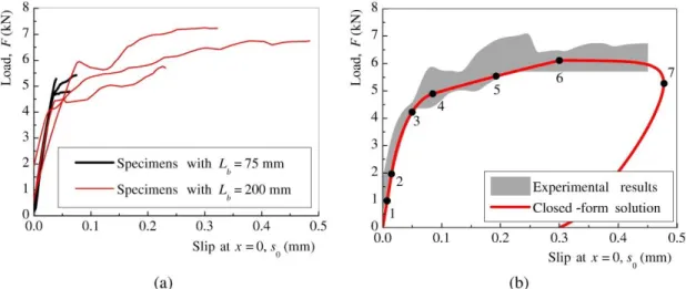
Figure 2.9 - Load-slip responses at the CFRP loaded end: (a) obtained from the experiments; and (b) comparison between the specimens with the longest bond length and the closed-form solution.
Figure 2.10 - Slip distributions at different states of the debonding process of the specimens: (a) S-10-75a; and (b) S-10-200b.
Figure 2.11 - Strain developed in the CFRP laminate at different states of the debonding process of the specimens: (a) S-10-75a; and (b) S-10-200b.
Figure 2.12 - Bond stresses developed along the bond length at different states of the debonding process of the specimens: (a) S-10-75a; and (b) S-10-200b.
Figure 2.13 - Definition of the effective bond length through the debonding load vs. bond length relationship.
Figure 2.14 - Illustration of the bond reponse of CFRP-to-steel double strap bonded joints. Figure 3.1 - CFRP-to-steel bonded joints: (a) side view; and (b) front view.
Figure 3.2 - Definition of: (a) pseudo cyclic; and (b) cyclic loading. Figure 3.3- Overview of the test setup.
Figure 3.4 - Load-slip at the loaded end for: (a) HIT; and (b) SIKA bonded joints. Figure 3.5 - Load vs. slip at the loaded end: (a) HIT; and (b) SIKA bonded joints.
Figure 3.6 - Some specimens after failure – cohesive in adhesive or hybrid in adhesive and CFRP-to-adhesive interface.
Figure 3.7 - Monotonic (S-M-03) and pseudo-cyclic (S-PC-02) bond-slip curves. Figure 3.8 - Stages of pseudo-cyclic bond-slip curves.
Figure 3.9 - Monotonic and pseudo-cyclic bond-slip curves: (a) HIT bonded joints; and (b) SIKA bonded joints.
Figure 3.10 - Cyclic bond-slip curve: (a) HIT bonded joint (b) SIKA bonded joint.
Figure 3.11 - Relation between the damage parameter (D) and: (a) the normalized dissipated energy; and (b) normalized slip.
Figure 3.12 - Relation between the normalized dissipated energy and the normalized slip. Figure 3.13 - Illustration of bond shear stress distribution at threshold loading state.
Figure 3.14 - Bond stress distribution along the bond length at threshold loading state for: (a) HIT; and (b) SIKA bonded joints.
Figure 3.16 - Dissipated energy: (a) per cycle; and (b) cumulative.
Figure 3.17 - Relation between: (a) the normalized interfacial and global dissipated energies; and (b) the normalized global dissipated energy and the normalized slip.
Figure 4.1 - (a) Freeze-thaw cycle procedure; and (b) aging chamber.
Figure 4.2 - Tensile stress-strain curves of adhesive coupon (a), tensile strength (b), modulus and rupture strain (c) and (d) after different number of freeze-thaw cycles.
Figure 4.3 - SEM images after tensile failure of adhesive coupons at 0 h (a), 1,000 h (b), and 10,000 h (c) freeze-thaw exposure.
Figure 4.4 - Load-slip responses of the specimens: (a) HIT laminate; and (b) SIKA laminate. Figure 4.5 - Failure modes of the HIT (a) and SIKA (b) bonded joints at 0 h (Reference). Figure 4.6 - Failure modes of bonded joints submitted to 2,500 h, 5,000 h and 10,000 h freeze-thaw cycles for HIT (c)-(e) and for SIKA (f)-(h).
Figure 4.7 - The bond-slip curves with freeze-thaw cycles: (a) HIT laminate; and (b) SIKA laminate.
Figure 4.8 - Equilibrium of forces in the CFRP/steel interface under temperature changes. Figure 4.9 - Comparison of global interfacial response of bonded joints induced by temperature changes and from equivalent external load: (a) HIT and (b) SIKA.
Figure 4.10 - Interfacial stress and interfacial slip distribution at some representative temperatures; and comparison of local interfacial response of bonded joints subjected to external loading and loads induced by temperatures; HIT (a)-(c) and SIKA (d)-(f).
Figure 4.11 - Strain distribution of materials at some representative temperatures during the freeze-thaw cycles: (a) HIT bonded joints; (b) SIKA bonded joints.
Figure 4.12 - Comparison between slip and bond stress distributions when thermal and mechanical loads are applied to the HIT bonded joint (a)-(b) (specimen H-M-01) and SIKA bonded joint (c)-(d) (specimen S-M-03).
Figure 4.13 - Comparisons between the strains developed in the CFRP laminates and steel plates when thermal and mechanical loads are applied to the HIT bonded joint (a)-(b) (specimen H-M-01) and SIKA bonded joint (c)-(d) (specimen S-M-03).
Figure 4.14 - Equivalent thermal cyclic bond-slip curves- after 833 mechanical cycles: (a) HIT (specimen H-C-03) and (b) SIKA (specimen S-C-02).
Figure 5.1 - Schematic view of bonded joints: (a) side view; (b) front view; and images of bonded joints with: (c) reference; (d) corroded; and (e) cleaned.
Figure 5.2 - Salt fog cycle procedure and corrosion chamber.
Figure 5.3 - Failure modes of (a) the reference and aged bonded joints with (b) HIT and (c) SIKA.
Figure 5.4 - Force vs. slip curves from reference and aged joints; (a) HIT and (b) SIKA. Figure 5.5 - Bond vs. slip curves from reference and aged joints; (a) HIT and (b) SIKA. Figure 5.6 - Pseudo-cyclic force vs. slip curves (a) aged HIT and (b) aged SIKA joints. Figure 57 - Pseudo-cyclic bond stress vs. slip curves (a) aged HIT and (b) aged SIKA joints. Figure 5.8 - Cyclic force vs. slip curves (a) aged HIT and (b) aged SIKA joints.
Figure 5.9 - Cyclic bond vs. slip curves (a) aged HIT and (b) aged SIKA joints.
Figure 5.10 - Monotonic force vs. slip curves after cyclic tests (a) aged HIT and (b) aged SIKA joints.
joints
Figure 5.12 - Local interfacial response under: (a) monotonic; and (b) cyclic loading.
Figure 5.13 - Relation between the damage parameter (D) and the normalized dissipated energy (Wd/Gf ).
Figure 5.14 - Relation between the damage parameter (D) and the normalized slip increment (S/Sult).
Figure 5.15 - Relation between the normalized dissipated energy (Wd/Gf) and the normalized
slip increment (S/Sult).
Figure 5.16 - Dissipated energy: (a) per cycle; and (b) cumulative.
Figure 5.17 - Relations between: (a) the normalized interfacial and normalized global dissipated energies; and (b) the normalized slip increment and normalized global dissipated energies. Figure 5.18 - Relation between the normalized load transmitted and the damage parameter (D) for: (a) HIT CFRP specimens; and (b) SIKA CFRP specimens.
Figure 5.19 - Relations between the dissipated energy and the slip increment (measured at 12.5 mm away from the CFRP loaded end) and the damage parameter for: (a) HIT CFRP specimens; and (b) SIKA CFRP specimens.
Figure 6.1 - Chemical structure of epoxy resin, curing agent and cured structures in HIT CFRP laminates.
Figure 6.2 – Joint specimens: (a) plate to shape adhesive coupons (b) adhesive coupon (c) and (d) CFRP-to-steel bonded joints.
Figure 6.3 - Set-up for tests of (a) CFRP-to-steel joints and (b) adhesive coupon
Figure 6.4 - Tensile properties of adhesive coupon with aging; stress-strain curves with aging (a); tensile strength (b); tensile modulus (c); rupture strain (d).
Figure 6.5 - Tensile fracture surface of adhesive coupon with aging; (a) 0h (b) 5,000h (c) and (d) 10,000h
Figure 6.6 - Curves of Tan of adhesive for different exposure times.
Figure 6.7 - Effects of accelerated salt fog aging on the bond capacity of CFRP-to-steel joints. Figure 6.8 - Images of failure surfaces of bonded joints for HIT CFRP.
Figure 6.9 - Images of failure surfaces of bonded joints for SIKA CFRP. Figure 6.10 - ATR-FTIR spectra for reference CFRPs and aged; HIT and SIKA.
Figure 6.11 - Storage modulus and tan for CFRP laminates with aging; HIT(a); SIKA(b). Figure 6.12 - SEM images of sectional area from reference and aged after polished. Figure 6.13 - Amplified SEM images of sectional area from HIT laminate aged 5,000h. Figure 6.14 - Galvanic corrosion mechanism of the CFRP-to-steel bonded joints under salt fog exposure.
List of Tables
Table 2.1 - Material properties of the CFRP laminate, adhesive and steel. Table 2.2 - Summarized test results of the double strap bonded joints. Table 3.1 - CFRP-to-steel bonded joints tested and ultimate load.
Table 4.1 - ID of the specimens and corresponding conditions of the tests. Table 4.2 - Tg values of adhesive after exposure to freeze-thaw aging. Table 4.3 - Ultimate load for joints subjected to freeze-thaw cycles.
Table 5.1 - ID of the CFRP-to-steel bonded joints, aging conditions and loading types. Table 5.2 - ID of joints, failure load, maximum bond stress and failure mode type. Table 6.1 - ID of specimens to test and types of environmental exposure.
Table 6.2 - Assignment of the characteristic absorption bonds in the FTIR spectra for the reference HIT laminates.
Nomenclature
Fexp, j = maximum experimental loads obtained in the jth sample
Fpred, j = maximum predicted loads obtained in the jth sample
n = sequential ID number in each class of tests
Lb = CFRP bond length
Leff = effective bond length
d1 and d2 = distance between consecutive strain guages
β = axial stiffness ratio
βHIT = axial stiffness ratio for HIT bonded joints
βSIKA = axial stiffness ratio for SIKA bonded joints
bCFRP = width of the CFRP laminates tCFRP = thickness of the CFRP laminates
ECFRP = Young’s modulus of the CFRP laminates bsteel = width of the steel plate
tsteel = thickness of the steel plate
Esteel = Young’s moudulus of the steel plate σmax = tensile strength of the materials σy = yield strength of steel
u = ultimate strain of adhesive and CFRP
Fmax = maximum load transmitted to single CFRP laminates FCFRP = load transmitted to the CFRP laminates
Fsteel = load transferred to the steel plate
Fthreshold = no interfaical damage occured before the load
ACFRP = cross section of the CFRP laminate Asteel = cross section of the steel plate uCFRP = displacement in the CFRP laminate usteel = displacement in the steel plate = bond stress within the interface 1 = maximum bond stress
critical = maximum bond stress at the loaded end
s = relative displacements between the bonded materials (or slip) smax = slip correspond the maximum bond stress
sult = slip when the interface starts debonding
σCFRP = axial stress in the CFRP laminate σsteel = axial stress in the steel plate CFRP = axial strain in the CFRP laminate steel = axial strain in the steel plate Ke = initial interfacial stiffness
D = damage parameter
wd = local interfacial energy dissipated at a particular cycle
Gf = local the total fracture energy
Ed = global interfacial energy dissipated at a partical cycle
Dlimit = damage limit of the bonded interface
Tg = glass transition temperature
CFRP = linear thermal expansion coefficient of CFRP laminates steel = linear thermal expansion coefficient of steel plate T = uniform temperature variation
Ti = initial temperature
Tf = final temperature
Tan int = value of energy dissipated at the fiber-matrix interface Tan c = value of energy dissipated in the FRP composite Tan mat = value of energy dissipated in the matrix
vf = fiber fraction
Ec = elastic modulus of composites Em = elastic modulus of matrix
Chapter 1
Introduction
Introduction
1.1 Brief considerations
There has been a lot of research on the application of FRP composites in civil engineering in the past 30-40 years, but only more recently the subject of strengthening of steel structures with CFRP composites has attracted the attention of researchers, which justifies the low number of publications available in the scientific community. In addition, the behavior of steel structures adhesively bonded with CFRP material is often dominated by the bonded CFRP-to-steel interface since most failures are known to take place at the interface between these two materials. For that reason, the literature review presented in the thesis is devoted to the summary of published data on bond aspects associated to the mechanical response and durability. Thus, some data on global behavior of the CFRP strengthening steel structural elements, e.g., girder, truss et al. are not emphasized in the present topic. In this section, a brief literature review is provided to give a general overview regarding some important studies of the thesis topic, i.e. on the “behavior and durability of CFRP-to-steel bonded joints under repeated loading and freeze-thaw and salt fog”. Of course, a more comprehensive literature review will be presented in each of the following chapters.
1.2 Motivation
A lot of steel bridges were built a few decades ago worldwide, which inevitably require strengthening or rehabilitation with the extending of the service life. It has been estimated e.g.
that more than 300,000 railway bridges exist in Europe in 2007, 22% of steel beam type and 14% steel/concrete composite bridges [1]. Overall, 35% of those bridges were more than 100 years old and only 11% less than 10 years old in 2007. The US Department of Transportation [2] estimated that almost 68.5 % of the Nation’s 604,493 bridges were 26 years old or older in 2010, with 11.5% of total bridges classified as structurally deficient, and 12.8 % of bridges were functionally obsolete. As an additional indicator, in 2013, out of 607,380 bridges, 200,000 bridges were steel bridges.
In China, steel bridges are widely used in railway infrastructure, which included 6550 steel girder bridges by the end of 2010 [3]. There are 4547 steel girder bridges that have serviced for more than 50 years under railway traffic in 2010, including 3884 steel plate girder bridges and 484 steel truss girder bridges [3].
All steel structures deteriorate with time, due to the service condition to which they are subjected. The reasons for deficiencies in steel structures placed in a civil infrastructure can be divided into two main aspects: (i) changes in the use of a structure, (ii) degradation of a structure. The former may be due to (a) increased live load, (b) increased dead load, (c) increased dead and live load; The latter may be caused by (a) corrosion (b) fatigue (c) impact vandalism, fire, blast loading or inappropriate structural alterations during maintenance, (d) design or construction errors [4].
According to the statistics on the main causes of damage of steel bridges, fatigue and environment accounted for 49% and 41% respectively. In general, weld defects, bolted or riveted details are stress raisers from which fatigue cracking may initiate and propagate. And corrosion is the another main cause for the degradation of a structure, leading to the reduction in the cross section of a steel part in the steel structures [4].
The traditional strengthening or rehabilitation technologies, namely welding, bolting and riveting as well as externally adhesive bonding with structural steel plate, have many disadvantages [5], namely (i) introduction of residual stresses to the steel elements; (ii) increase of localized stresses; (iii) extra weight added; and (iv) further corrosion. Therefore, a new and alternative technology to the traditional methods is needed for strengthening or rehabilitation of steel structures.
Carbon fiber reinforced polymer (CFRP) composites have numerous advantages that might be interesting to explore in order to positively respond to this real need of strengthening steel structures, such as: (i) light weight; (ii) high strength and stiffness; (iii) excellent fatigue [6, 7]; and (iv) good long-term performance [8, 9]. Compared to traditional strengthening technology using steel material, CFRP adhesively bonding technology has some advantages such as easy construction and maintenance as well as a more uniform stress distribution over the bonded area [10]. Although it is expected to be used as an externally strengthening material for civil engineering structures, and many studies have been published devoted to different aspects of design and durability of reinforced concrete elements, much scarcer data are found when the members to be strengthened are built with structural steel.
Recently, studies on application of CFRP laminates in steel bridges have been focused on some possibilities, including: (i) increase or restore the tensile or flexural capacity of steel elements, for example, bond to the steel truss element and the tension flange of the steel girder due to corrosion damage, (ii) increase fatigue resistance of steel elements, for example, strengthening of riveted elements against fatigue crack propagation [11].
It is known that the primary challenge towards the successful implementation of FRP materials for strengthened steel structures is the performance of the bond due to the premature debonding of the CFRP laminate from the substrate. Thus, it is of extreme importance to improve the actual knowledge of the bond stress transfer and failure mechanism between both bonded materials. Moreover, the behavior of the strengthened structures is important when one has to consider and support complicated loading conditions, namely repeated loading (e.g., earthquake excitation, traffic load and long-term temperature changes) and face long-term service environments (freeze-thaw and salt-fog).
1.3 State of the Art
In the scientific community, behavior of bonded CFRP/steel interface often has been evaluated through examining the response of CFRP-to-steel bonded joints. These bonded joints models
(direct-shear tests model), as well as fabricating two steel plates together with CFRP composites (double-strap bonded joints model). With the bonded joints models mentioned above, considerable works have been done to examine the bond carry capacity and failure modes under monotonic loading [12-15]. Some variations also were considered to ascertain the effects of the properties of CFRP, e.g., modulus and width of CFRP [12], and of properties of the adhesive, namely its ductility and layer thickness [13, 14], as well as of the treated surface of the adherent materials [15].
The bond properties are often directly related to a local bond stresses developed in the interfacial and corresponding relative displacement between the adherents, i.e., CFRP composite and steel. However, the axial stresses transfer in the bonded materials and the bond shear stress transfer within the bonded interface are different on the direct-shear tests model and the double-strap bonded joints model caused the latter is made without constrain of the steel substrate.
Yu et al. [13] experimentally studied the bond response of the CFRP-to-steel bonded joints through testing series of direct-shear bonded joints (i.e., pull-push tests) with different type of adhesive and CFRP laminates. Local bond-slips were obtained and the bond stresses transfer mechanisms were interpreted. Further, Fernando et al. [16] derived closed-form solutions based on the bond-slip model associated with a ductile adhesive to interprete the bond stresses transfer process within the bonded interface. However, there are some experimental studies have been conducted for double strap tests (i.e., pull-pull tests) [12, 17, 18] but very few bond-slip curves were obtained from this loading condition [17, 18]. Moreover, the calculation method of these bonds-slip curves has not considered the effects of the deformation of steel plate, in this case, on the relative deformation of the bonded materials, i.e., CFRP and steel (slip).
Repeated loading lower than the monotonic strength capacity adopted in the design guideline leads to bond accumulative damage and may produce catastrophic failure of the reinforced system without pre-inspection. Currently, the global response (force vs. deformation of the bonded joints) of the CFRP-to-steel boned joints under fatigue loading has been studied in [19-21]. Colombi and Fava [19] assessed the fatigue behavior of CFRP-to-steel double strap joints through observing crack initiation, progression and debonding up to failure, and associated it
to the reduction of global stiffness (force vs. deformation of the bonded joints) of bonded joints with fatigue load. It was observed that the crack initiation was associated with a stiffness reduction of 98%, after subsequent gradual crack progression, quicker debonding and final sudden failure when stiffness reduced to 95% and 90% of the initial value. Other two fatigue studies conducted by Liu et al. [20] and Wu et al. [21] focused on the effects of the different level fatigue loads on the residual strength capacity.
Freeze-thaw is a common operating condition for outdoor structures and requires attention to the behavior/durability of externally bonded reinforced systems. Freeze-thaw cycles act on the CFRP-steel bonded system primarily via degrading the adhesive and the interfaces between adhesive and the bonded materials. Not many studies regarding adhesive exposure to freeze-thaw cycles exist, one being authored by Agarwal et al. [22]who exposed adhesive coupons of SIKA-30 and SIKA-330, to 40 cycles of 16h at -18°C followed by 8h at 38°C and 100% relative humidity and found 9% and 19% reduction, respectively, on the tensile strength and elastic modulus of SIKA-330 and no significant degradation of strength and 14% reduction of the elastic modulus for SIKA-30. The degradation of the interfaces has often been found to be significantly more important than that of the adhesive [23]. Kim et al. [24] showed that steel-to-steel double lap shear joints subjected to 100 freeze/thaw cycles (8h -20°C, 16h room temperature per cycle) had their failure mode changed from cohesive (in the adhesive) at 0 h to adhesive failure.
One of the studies from Heshmati et al. [25] reported that the initial slope of the bond shear stress vs. slip (relative deformation between the adherents) after freeze-thaw aging remained the same for all the specimens irrespective of the aging condition (pre-conditioned in distilled water or salt water or humidity prior to freeze-thaw aging), or the presence of moisture (without preconditioned prior to freeze-thaw aging). Another study conducted by Heshmati et al. [26] indicated that moisture had not evident effect on the bond capacity and failure mode for aging by freeze-thaw cycles.
Another concern results from the eventual contact of carbon fiber reinforced polymer composite materials (acting as a cathode) with most metals as anodes in the presence of an electrolyte e.g.
from salt water, and the creation of galvanic coupling [27-30]. Galvanic coupling has been found to degrade the CFRP composite itself besides resulting in more severe metallic corrosion [27-30].
Kim, Bumadian and Park [31] investigated the effects of galvanic coupling on the bond durability of CFRP-to-steel joints and found that the steel acting as anode was significantly corroded in the edges of the bonded areas and debonding failure of CFRP took place. The authors indicated that the adhesive layer impeded galvanic interaction between the steel and conductive carbon fibers. Recent studies on accelerated corrosion of CFRP-to-steel bonded joints by Batuwitage et al. [32, 33] found that failure of the joints changed from interfacial failure between adhesive and steel to CFRP rupture failure, and a significant reduction occurred in the tensile strength of CFRP. Increasing the number of CFRP layers increased the durability of the bonded joints.
1.4 Thesis objectives
The bond properties of the CFRP-to-steel interface subjected to service loadings and bond durability of the CFRP-to-steel exposed to long-term service environments are, therefore, important concerns and the results of the studies developed worldwide by the researchers on these subjects should firstly point out to the improvement of national and international codes, which are quite useful for designers.
Regarding what is mentioned above, this thesis includes the study of the bond behavior and durability of CFRP-to-steel bonded joints under repeated loading and aggressive conditions namely freeze-thaw and salt fog.
The main objectives of this work are as follows:
◼ Develop an experimental program of mode-II monotonic testing on CFRP-to-steel
double strap bonded joints with different bond lengths. Propose a mathematical model for the bond response and derive closed-form solutions to compare with the experimental results;
bonded joints with two different CFRP laminates. Obtain results capable of explaining the bond cumulative damage mechanism and enabling the proposal of a based on which to propose a fatigue limit for CFRP-to-steel bonded joints under Mode-II loading;
◼ Make an assessment of the bond durability of CFRP-to-steel bonded joints subjected
to freeze-thaw cycles for a relative long time and ascertain the bond degradation mechanism through materials characterization and thermal stress analysis;
◼ Make an assessment of the durability of CFRP/steel bonded system subjected to salt
fog spray through the degradation mechanism of the materials and bond response;
1.5 Organization of the thesis
The objectives presented above required the treatment of issues and procedures that are organized in different chapters as follows. A flow chart of the thesis structure is illustrated (Figure 1.1) to facilitate understanding of organization of the thesis.
Chapter 1
In this chapter the motivation of the study is presented in a summarized way. A brief literature review is provided also to give a general overview on some important studies of the thesis topic. The objectives that are intended and a brief description of the organization of the thesis are conducted.
Chapter 2
The content of this chapter is essentially part of a published article: Yang YM, Biscaia HC, Chastre C, Silva, MAG. Bond characteristics of CFRP-to-steel bonded joints. J Constr Steel Res 2017;138:401-419, DOI: 10.1016/j.jcsr.2017.08.001.
A series of CFRP-to-steel double-strap bonded joints with different bond length are tested under monotonic loading. A mathematical model capable of reflecting on the bond response of CFRP-to-steel boned joints is proposed. Based on the model, closed-form solutions are derived to better understand the full-range debonding process for double-strap bonded joints (i.e., pull-pull tests) and compared with the experimental results.
Chapter 3
The content of this chapter is essentially part of a published article: Yang YM, Silva MAG, Biscaia HC, Chastre C. CFRP-to-steel bonded joints subjected to cyclic loading: An experimental study. Compos Part B: Engineering 2018;146:28-41, DOI: 10.1016/j.compositesb.2018.03.039.
Pseudo-cyclic and cyclic loading are applied in CFRP-to-steel bonded joint with two different CFRP laminates to examine the bond response. Pseudo-cyclic and cyclic bond vs. slip and force vs. slip curves are obtained, based on which, local and global interfacial cumulative damage are deeply analyzed.
Chapter 4
The content of this chapter is essentially part of the manuscript under review in Composites Structure (Elsevier) under the title “Bond durability of CFRP-to-steel bonded joints subjected to freeze-thaw”. The authors are Yongming Yang, Manuel A G Silva, Hugo Biscaia and Carlos Chastre.
This chapter presents the degradation data regarding CFRP-to-steel bonded joints and adhesive subjected to 10,000h freeze-thaw aging (833 freeze-thaw cycles, each cycle includes 6h freeze at -20°C followed by 6h thaw at 20°C). Degradation mechanism is deeply discussed through relating failure modes of bonded joints, bond capacity and properties of adhesive as well as the thermal stress developed within the bonded interface during the freeze-thaw aging.
Chapter 5
The content of this chapter is essentially part of the manuscript under review in Composite Part B: Engineering (Elsevier) under the title “Monotonic and cyclic bond response of CFRP-to-steel joints after salt fog exposure”. The authors are Yongming Yang, Hugo Biscaia, Manuel A G Silva and Chastre Carlos.
The studies in this chapter focused on the bond response of CFRP-to-steel joints under loading after salt fog exposure, as a complementary to the works conducted in chapter 3 and chapter 6. Chapter 6
The content of this chapter is essentially part of the manuscript under review in Composite Part B: Engineering (Elsevier) under the title “Material degradation of CFRP-to-steel joints subjected to salt fog”. The authors are Yongming Yang, Manuel A G Silva.
This chapter presents the degradation data regarding CFRP-to-steel bonded joints and adhesive subjected to 10,000h salt fog aging (each cycle includes 18h salt spray followed by 6h dry at 35°C). This study focuses on the degradation of materials namely CFRP and adhesive. The degradation mechanisms of CFRP laminates and adhesive are described.
Chapter 7
This chapter presents conclusions regarding each analyzed subject, some recommendation based on the knowledge obtained and also some issues that may be the aim of further research. Chapter 8
This chapter presents all the references cited in the thesis
Chapter 2
Bond characteristics of CFRP-to-steel
bonded joints
Bond characteristics of CFRP-to-steel bonded joints
2.1 Introduction
Fiber Reinforced Polymer (FRP) sheets and strips, if adequately bonded to steel structures, have been shown to be effective enough on the enhancement of both the mechanical characteristics and fatigue life. Some research shows that significant increase in the stiffness and strength of the repaired beams can be achieved through the use of CFRP laminates [34-38]. A state-of-the-art review on steel beams externally strengthened with FRP composites under fatigue loading was published in 2014 [39], in which different rehabilitation techniques were discussed and the experimental results from previous research were summarized. In that study [39], it was shown that the mechanical properties of beams strengthened with FRP composites actually improved when compared to the unstrengthened beams. Among other aspects, it was found that the use of FRP composites can delay the initial cracking, reduce the crack growth rate, extend the fatigue life and decrease the stiffness decay with residual deflection.
As is well known, the primary challenge to the successful implementation of FRP composites for the strengthening of steel structures is the performance of the bond between both materials, which is susceptible to premature debonding. Premature debonding of the CFRP laminate from the substrate puts the bond stress transfer between materials at risk. This is an important failure mode that has recently attracted attention to national and international codes by adding useful guidelines for designers. The complexity of the mechanical response of a full-scale reinforced section does not allow the bond debonding mechanism to be clearly investigated. Thus, as a first step, more research [13, 14, 40-42] has been conducted with direct-shear tests of CFRP laminates/sheets attached to the surface of steel blocks (i.e., pull-push test), as well as double-strap bonded joints by putting together two steel plates with CFRP composites (pull-pull test) [12, 17, 18, 43] in order to enhance the understanding and modeling of the debonding failure mechanism coincident with a fracture Mode II loading.
Understanding and analyzing those failure modes is very important in seeking the control methods that can improve the reliability of the reinforced system. Even so, appropriate surface preparation of the steel and CFRP has been imposed to ensure that the failure will not occur within the interface between materials [44]. The failure modes associated to CFRP-to-steel bonded joints may have many possibilities such as: (i) the properties of the adhesive; (ii) the adhesive layer thickness; (iii) the stiffness of CFRP composites; and (iv) the bond length. Generally, brittle adhesive with low strength leads to cohesive failure, whereas high strength [41], ductility adhesive [13, 41] or thicker adhesive [14] leads to the delamination of the CFRP composite, whilst a high modulus CFRP seems to induce either the delamination or the rupture of CFRP composite [12, 18]. It should be noted that the change of the failure mode with different bond lengths was reported in [12, 18].
Like concrete [45], an interesting aspect of the bond behaviour of the CFRP-to-steel interface is that there is an effective bond length beyond which an extension in the bond length cannot increase the ultimate capacity of the joint. In fact, the correct evaluation of the effective bond length is an important part of the whole strengthening design, which can avoid the waste of composite materials in strengthening projects. Therefore, Sweedan et al. [46] studied the influence of using mechanical fasteners on CFRP-to-steel bonded joints to improve their strength. However, they found that when the distance between bolts increased from 100 mm to 168 mm, the influence of the bolts on the final strength was almost insignificant [46].
Knowledge of the interfacial behaviour of the joint plays an important role. Usually, this interfacial behaviour is quantified with a local relationship of the joint through the relation between the bond stress developed within the joint and the relative displacements (or slips) between bonded materials. The shape of the bond-slip curves is closely related to the properties of the adhesive (linear or nonlinear) [13, 41] with the failure mode and the geometric conditions of the specimens being relegated to a second plan. A considerable number of bond-slip curves of CFRP-to-steel bonded joints were obtained from pull-push tests and the derivation of closed-form solutions can be helpful for the understanding of the full-range debonding process [16, 47, 48]. To the best of the authors’ knowledge, a lot of experimental studies have been conducted for double strap tests (i.e., pull-pull tests) [12, 17, 18, 43] but very few bond-slip curves were obtained from this loading condition [17, 18]. An excellent review by Zhao [49] also suggested that further research is required to determine bond-slip relationships based on those tests. In the present chapter, a series of CFRP-to-steel double-strap bonded joints (pull-pull tests), with different bond lengths, was carried out. The failure modes are herein reported and the bond-slip relationship in each test was obtained. Based on the experimental results, a tri-linear bond-slip model is proposed and it is used for the determination of a closed-form solution that, despite easy implementation, provided accurate results when compared with those of the
experiments. The strength of the CFRP-to-steel interface, the distribution of the slips, strains in the CFRP laminate or in the steel and bond stresses within the interface are analyzed and discussed.
2.2 Experimental program and failure modes
2.2.1 Materials
Pultruded unidirectional CFRP laminates, steel plates and adhesive to bond the structures were used to make the specimens for testing. The CFRP laminate, which was 1.26 mm thick and 10 mm wide, was bought from a SIKA supplier as well as the bonding agent, a two-part room-temperature curable bonding agent, SIKADUR-30. The steel plate was 5 mm thick and 50 mm wide and it was cut in different lengths, as required by the different bonding lengths. The main mechanical properties of these three materials were experimentally obtained from tensile tests of flat coupons in accordance with standards ASTM D 3039 [50], ISO 527-2-1993 [51] and EN 10025:2004 [52]. The average values obtained from these tests are reported in Table 2.1. The coefficients of variation, cov, are shown in the same table.
Table 2.1 - Material properties of the CFRP laminate, adhesive and steel. Materials Young’s modulus
E (MPa) Tensile strength max (MPa) Yield strength y (MPa) Ultimate strain εu (%)
Mean cov Mean cov Mean cov Mean cov
SIKA laminate 163,300 4.2 1840 2.8 N/A N/A 1.13 9.6
SIKA-30 adhesive 8432 3.0 21.76 7.64 N/A N/A 0.34 12.5
Steel 210,000 N/A 540 N/A 400 N/A N/A N/A
2.2.2 Preparation of the specimens and test setup configuration
The double strap test was selected to study the bond properties of the CFRP-to-steel interface. The tests were conducted on specimens with the dimensions and configurations shown schematically in Figure 2.1. There are several advantages of the geometry chosen for the specimens. The mechanical clamping with two steel plates fastened with metallic bolts, applied on one side of the sample, ensured that the debonding failure would occur on the monitored side of the sample. Moreover, the 10 mm long gap at the center of the specimen could minimize or even prevent localized effects such as stress concentrations due to the external pressure applied to the clamped steel plates.
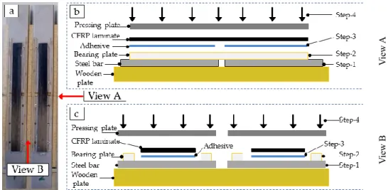
Figure 2.1 - Scheme of the specimens: (a) lateral view; and (b) front view.
The steel plates were grit-blasted and then cleaned with acetone to remove dust, grease and other contaminants before bonding the joints using a SIKA bonding agent, as recommended by the supplier. Two plastic 2.26 mm bars were used as bearing plates to make sure that a uniform 1 mm constant thickness of the adhesive was applied in all specimens. An illustration of process of preparation of CFRP-to-steel bonded joints is presented in Figure 2.2, in order to facilitate understanding. At end, the specimens were cured at room temperature (~24ºC) for 2 weeks before testing. V iew A V iew B
Figure 2.2 - Process of preparation of CFRP-to-steel bonded joints: (a) bonded joints, (b) Schematic view of preparation process from view A and (c) from View B
A total of 35specimens with different bond lengths were prepared and tested under a pulled shear load in order to create a debonding failure mode consistent with the fracture Mode II. Different bond lengths were considered to analyze the differences between load-slip responses and to find out the effective bond length (Leff) of the CFRP-to-steel interface, which is known
in the literature, e.g. [53-56], by the length beyond which the strength of the interface can increase no further. The axial stiffness ratio of the specimens is defined as:
steel steel steel CFRP CFRP CFRP E t b E t b β = (2.1) where bCFRP, tCFRP and ECFRP are the width, the thickness and the Young’s modulus of the CFRP
laminate, respectively; and bsteel, tsteel and Esteel are the width, the thickness and the Young’s
modulus of the steel plate, respectively. For the values of the materials used, the axial stiffness
β defined in (2.1) is equal to 0.039, which is an important parameter on the debonding behaviour
in pull-pull tests as proved in [57]. The identification of the specimens and the bonded lengths used in the experimental program are presented in Table 2.2. For instance, S-10-25a/b/c, the initial letter "S" means that the CFRP laminate used is from SIKA supplier; the first number, "10", corresponds to the width of the CFRP laminate and the second number, "25", represents the bonded length; the letters "a", "b" and "c" at the end of the reference code means that the same test with the same characteristics was repeated three times.
The CFRP laminates of the specimens with different bond lengths, Lb, were set up with strain
gauges as shown schematically in Figure 2.1. The first strain gauge and the last one were bonded 12.5 mm from the CFRP loaded and free ends but the intermediate strain gauges were all bonded at an interval of 25 mm. All tests were performed on a universal tensile machine with a maximum capacity of 50 kN. The tensile force transmitted to the specimens was monotonically imposed with a displacement rate of 1 mm/min. Figure 2.3 shows an overview of the test setup configuration used for testing the CFRP-to-steel interface under those conditions.
Table 2.2 - Summarized test results of the double strap bonded joints. Designation of the specimens Bond length, Lb (mm) Average debonding load per interface,
Fmax (N) Instrumentation (strain gauges) Observed failure modes
S-10-10a/b/c 10 958 Not instrumented A
S-10-25a/b/c 25 2822 Not instrumented A
S-10-50a/b/c 50 5594 2 (d1 = 12.5 mm; d2 = 25 mm) A S-10-60a/b/c 60 6068 3 (d1 = 10.0 mm; d2 = 20 mm) A S-10-75a/b/c 75 5180 3 (d1 = 12.5 mm; d2 = 25 mm) A S-10-90a/b/c 90 7156 4 (d1 = 7.5 mm; d2 = 25 mm) A S-10-100a/b/c 100 5661 4 (d1 = 12.5 mm; d2 = 25 mm) A S-10-110a/b/c 110 6247 5 (d1 = 5.0 mm; d2 = 25 mm) A S-10-125a/b/c 125 6102 5 (d1 = 12.5 mm; d2 = 25 mm) A S-10-135a/b 135 7117 6 (d1 = 5.0 mm; d2 = 25 mm) A S-10-150a/b/c 150 5836 6 (d1 = 12.5 mm; d2 = 25 mm) A S-10-200a/b/c 200 6591 8 (d1 = 12.5 mm; d2 = 25 mm) A
Note: A means that the failure mode occurred within the CFRP laminates and the adhesive interface (CFRP/Adhesive Interface Debonding); d1 and d2 – distances between consecutive strain gauges as shown in Figure 2.1.
Figure 2.3 - Overview of the test setup.
2.2.3 Failure modes
Zhao and Zhang [49]have described the possible failure modes that can be observed in CFRP-to-steel interfaces. Among all the failure modes described [49], in the current work the debonding of the interface between the CFRP composite and the adhesive was usually observed in all samples. However, in some parts of the bond length, a small and very thin surface of the resin remained bonded to the CFRP laminate after its complete separation from the resin. Therefore, in Table 2.2, it is stated that the failure mode is adhesive. As an example, Figure 2.4 shows this typical failure mode on four different samples with different bonded lengths randomly selected from the batch of 35 specimens. This figure shows two different perspectives: one is the failure mode observed from the side of the CFRP laminate, whereas the other is the perspective given of the failure mode observed from the steel plate. It is also important to mention that visible cracks or parts of the bonding agent debonded from the steel plates were never observed in the tests herein performed.
Figure 2.4 - Overall overview of the typical failure modes observed on some samples with different bonded lengths.
2.3 Local bond-slip behavior
2.3.1 Experimental bond-slip relationship
The bond-slip relationship of the CFRP-to-steel interface was obtained from the data collected by the strain gauges bonded on the CFRP laminate along the bond length. The bond stresses developed within the interface were calculated by assuming that between two consecutive strain gauges, the bond stress is constant according to [13, 41, 18, 58-61]:
(
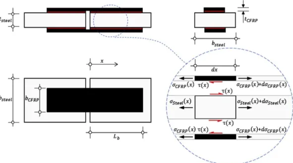
)
i i i CFRP i CFRP CFRP CFRP i x x t E x − − = + + + 1 , 1 , 2 / 1 (2.2) where εCFRP,i+1 and εCFRP,i are, respectively, the strains in the CFRP laminate at point i+1 andpoint i; and the difference (xi+1 - xi) is the distance between two consecutive points. As will be
shown later, the bond stresses developed along the bond length are not constant and, therefore, the distances between strain gauges should be as small as possible in order to improve accuracy. On the other hand, the determination of the relative displacements (or slips) between the CFRP laminate and the steel plate assumed a linear distribution of the strains between two consecutive points [59] and in the present work they were determined as follows:
( )
(
)
( )
(
)
(
1) ( )
1 , 1 , 1 , 1 , 1 2 2 1 + + + + + + + − + − − + = + − =
+ i i i i steel i steel i i i CFRP i CFRP x x CFRP steel i i x s x x x x x s dx x s i i (2.3)where s(xi+1) is the slip at point xi+1 and εsteel,i+1 and εsteel,i are the strains in the steel plate at the
points i+1 and i, respectively. It should be noted also that, for the determination of Eq. (2.3),
S-10-200b
S-10-100a
S-10-50b
Eq. (2.2). Thereof, where the bond stress is zero it means that slip is zero as well and Eq. (2.3) can be derived and used towards the CFRP loaded end (centre of the double strap bond joint). Furthermore, the strains in the steel plate (εsteel) can be found from the equilibrium condition of
the test, i.e. using the loads measured from the tensile machine and from the loads in the CFRP composite. Due to the determination of the bond stresses at point i+1/2, an average value of the slips determined from Eq. (2.3) should be made between two consecutive points:
(
) ( ) ( )
2 1 2 / 1 i i i x s x s x s + = + + (2.4)The bond-slip relationship is finally determined by associating the average bond stress calculated from Eq. (2.2) and the average slip calculated from Eq. (2.4). However, due to the slips developed in both CFRP ends, the determination of the slips must firstly be made by the identification of a point (or points) of the bond length where the bond stress is zero, so the slip is zero as well. From that point forward, Eq. (2.3) should then be used without affecting the outcome of the interfacial bond-slip relationship [62, 63].
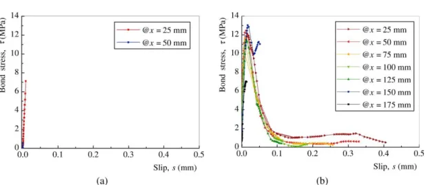
Figure 2.5 shows the differences between the interfacial bond-slip relationships obtained when the sample has a short (Figure 2.5a) or a long (Figure 2.5b) bonded length. From these results, it can be noticed that only from the samples with a sufficient bond length is it possible to fully define the interfacial bond-slip relationship. In this case of bond between the CFRP laminate and the steel plate, three different and distinct stages can be distinguished in the bond-slip relationship. The bond-slip relationship of the CFRP-to-steel interface can first be characterized by small slips and an almost linear increase of the bond stress, until a maximum bond stress value is reached. From this point on, the increase of the slips originates a decrease in the bond stress until a lower and constant bond stress is reached. Then, after this constant bond stress, a sudden and noisy rupture of the CFRP-to-steel interface was observed and heard and, therefore, no further data was collected from the samples.
The definition of the nuclear points of the interfacial bond-slip model can be made only if the interface has a sufficiently long bond length [59, 62-64]. Therefore, only the specimens with the longest bond lengths (S-10-200a, S-10-200b and S-10-200c) were chosen to define those points and their average values were calculated. Thus, the maximum bond stress τ1 and the corresponding slip s1 were found to be 11.55 MPa and 0.015 mm, respectively, whereas bond stress τ2 and the corresponding slip s2 were set at equal to 1.40 MPa and 0.085 mm, respectively. The ultimate slip and the last nuclear point in the proposed bond-slip relationship was s3 = 0.300 mm.
Figure 2.5 - Experimental bond-slip relationship obtained from the specimens with: (a) a short bond length (S-10-75a); and (b) the longest bond length (S-10-200b)
2.3.2 Proposed bond-slip model
Based on the experiments, a tri-linear bond-slip model is proposed for the simulation of the local behaviour of the CFRP-to-steel interface in CFRP/steel double strap joints which is quite similar to the local behaviour observed by Ren et al. [65] for grouted rockbolts. The interfacial bond-slip model is, therefore, built with an initial Elastic stage (E), followed by a linear Softening (S) stage that ends when a stage (C) of constant shear stress initiates. The interfacial bond-slip model can be mathematically defined as follows:
𝜏(𝑠) = { 𝜏1 𝑠1 𝑠 if 0 ≤ 𝑠 ≤ 𝑠1 𝜏2−𝜏1 𝑠2−𝑠1⋅ 𝑠 + 𝜏1⋅𝑠2−𝜏2⋅𝑠1 𝑠2−𝑠1 if 𝑠1< 𝑠 ≤ 𝑠2 𝜏2 if 𝑠2< 𝑠 ≤ 𝑠3 0 if 𝑠 > 𝑠3 (2.5)
where τ1 and τ2 are, respectively, the maximum bond stress and the bond stress corresponding to the constant stage; s1, s2 and s3 are, respectively, the slip at maximum bond stress, the slip at the end of the linear softening stage and the ultimate slip which represents the end of the constant stage and from that point forward the complete debonding between materials initiates.
Figure 2.6 - Comparison between the experimental and the proposed bond-slip relationships.
2.4 Analysis of the debonding failure process
2.4.1 Main hypotheses and equilibrium conditions
In the formulation of the model leading to a closed-form solution, the following assumptions were made:
• the strain distribution across the width of the CFRP composite is constant and, consequently, the bond stresses developed along the width of the bonded length are constant;
• the cross section of the FRP composite stays unchanged during the full debonding failure process;
• a sufficiently long bond length is assumed, which means that the maximum strength of the interface is always reached and the effective bond length is ensured;
• the load applied to the FRP composite induces interfacial shear on the FRP-to-steel interfaces, which is consistent with the fracture Mode II debonding process and resulting into rupture modes that are in agreement with this fracture mode;
• the debonding failure process to be modeled is consistent with that observed from the tests, which means that other possible debonding failure processes lie outside of the scope of the proposed model and, consequently, of this work.
In addition to the above assumptions, it should be noted that the closed-form solution intends to simulate the debonding failure process of the double strap joints tested accordingly to the experimental program. Despite the fact of the same methodology could be used to predict the debonding failure process of other test setup configurations, adequate boundary conditions (see Appendix A) should be used for each case.