UNIVERSIDADE DE LISBOA FACULDADE DE CI ˆENCIAS DEPARTAMENTO DE INFORM ´ATICA
Resource Savings in Delay Tolerant Networks
Gustavo dos Santos Correia
MESTRADO EM ENGENHARIA INFORM ´
ATICA
Especializac¸˜ao em Engenharia de Software
Dissertac¸˜ao orientada por:
Prof. Doutor Hugo Alexandre Tavares Miranda
Agradecimentos
Agradec¸o ao meu orientador Hugo Miranda pela constante disponibilidade e apoio. Foi incans´avel durante todo o desenvolvimento deste trabalho de modo a torn´a-lo o melhor poss´ıvel. Muito obrigado professor, foi um prazer trabalhar consigo.
N˜ao posso deixar de agradecer `a minha fam´ılia por todo o apoio ao longo destes anos. Aos meus pais, Maximiano e Maria Helena, por todo o esforc¸o que fizeram para que fosse poss´ıvel concluir o curso. Ao meu irm˜ao Gonc¸alo e ao meu primo Jo˜ao Pedro pelo apoio.
Por fim, mas n˜ao menos importante gostaria de agradecer `a FCUL e a todas as pessoas que me acompanharam neste percurso acad´emico. Em especial, gostaria de mencionar o Pedro Caldeira, Bernardo Almeida, Miguel Viola, Rui Poeiras e Jo˜ao Santos pelo apoio ao longo destes anos. Foram muito importantes neste percurso!
Trabalho parcialmente suportado pela Fundac¸˜ao para a Ciˆencia e Tecnologia, projeto doit - Decentralization and optimization of IoT aware business processes, PTDC/EEI-ESS/5863/2014 e pelo projecto plurianual LASIGE, UID/CEC/00408/2013.
Resumo
Este documento foca-se no trabalho que foi feito na dissertac¸˜ao de mestrado no Depar-tamento de Inform´atica da Faculdade de Ciˆencias da Universidade de Lisboa ao longo de um ano. O objectivo inicial foi criar um prot´otipo de middleware em ambiente de simulador que servisse o prop´osito de facilitar disseminac¸˜ao de dados num ambiente urbano de cidade inteligente.
Apesar de apont´armos para uma soluc¸˜ao mais gen´erica poss´ıvel, por de tr´as deste objectivo e servindo de motivac¸˜ao existe um cen´ario de caso de uso no qual nos foc´amos. Este cen´ario descreve uma cidade na qual a recolha do lixo tem que ser otimizada e em cada caixote existe um sensor que produz leituras do n´ıvel atual de enchimento. O desafio coloca-se em disseminar a informac¸˜ao produzida por estes sensores de uma forma eficaz e sem grandes gastos de recursos. Como tal, recorremos ao facto de j´a existir uma infraestrutura subjacente para resolver o problema. Atrav´es da utilizac¸˜ao de carros de pol´ıcia, bombeiros, t´axis ou por exemplo cami˜oes do lixo, fazemos com que estes ajudem na recolha das leituras feitas pelos sensores. O facto de esta recolha de leituras ser feita localmente por ve´ıculos que circulam na cidade, permite que as baterias dos sensors sofram uma descarga menor do que se tivessem que enviar diretamente a informac¸˜ao para o destino final mas utilizando recursos mais dispendiosos.
Para melhorar esta ideia e de forma a que o resultado final fosse o mais completo poss´ıvel, comec¸´amos ent˜ao por fazer um estudo do estado da arte. Ao ler e considerar trabalho feito nas ´areas de espac¸os de tuplos, redes tolerantes a atraso, cidades inteligentes, simuladores de redes, redes de sensores e difus˜ao epid´emica foi poss´ıvel melhorar conside-ravelmente o produto final desta dissertac¸˜ao. Este estudo de outros trabalhos ´e sem d´uvida um passo muito importante no decorrer desta dissertac¸˜ao, pois atrav´es de observac¸˜ao, quer de lacunas, quer de pontos fortes existentes noutras soluc¸˜oes, permitiu considerar e pensar de forma competente a soluc¸˜ao a desenvolver. Partindo ent˜ao deste estudo foi definido um modelo de sistema que permitiu perceber de forma eficaz alguns requisitos e condic¸˜oes que tinham de ser cumpridos.
Dado este trabalho inicial foi ent˜ao definido a especificac¸˜ao para o middleware. Foi determinada uma semˆantica para o espac¸o de tuplos que suporta a persistˆencia de dados para cada um dos n´os da rede. Ap´os isto, foi implementado uma vers˜ao de espac¸os de tuplos em C/C++ que cumprisse esta mesma semˆantica. Em comunh˜ao foi elaborado um
protocolo que permitisse que estes espac¸os de tuplos fossem sincronizados entre os v´arios n´os existentes na rede. Este protocolo foi concebido utilizando conceitos de flooding e difus˜ao epid´emica. Para al´em disso foi criado um canal priorit´ario para que se podesse proceder ao envio de leituras cujo o cariz fosse mais importante. De forma a manter um certo n´ıvel de eficiˆencia no middleware, foi tamb´em criado um mecanismo de remoc¸˜ao de tuplos duplicados na rede. Este mecanismo recorreu ao uso de ep´ocas definidas em tempo de configurac¸˜ao. Foi tamb´em delineado uma forma parcimoniosa de serializac¸˜ao dos tuplos trocados na rede com o objetivo de melhorar a eficiˆencia deste middleware. Por fim, cri´amos uma forma de atualizac¸˜ao de c´odigo para os sensores que tamb´em utiliza a infraestrutura de cidade para se disseminar para cada sensor.
Toda esta implementac¸˜ao foi feita especificamente para o Network Simulator 3, sendo desenvolvida em C/C++. O simulador de redes em quest˜ao tornou-se extremamente ´util pois permitiu testar numa fase embrion´aria um cen´ario que dado a escala seria d´ıficil de avaliar numa situc¸˜ao real. Pelos in´umeros m´odulos j´a existentes de raiz, foi poss´ıvel implementar caracter´ısticas como comunicac¸˜ao 3G/4G ou simulac¸˜ao de bateria em cada sensor.
De forma a oferecer uma grande flexibilidade para que este middleware possa ser aplicado em diferentes cen´arios com diferentes caracter´ısticas, cri´amos uma configurac¸˜ao parametriz´avel de valores que fazem com que o middleware se adapte. Esta flexibiliade ´e muito importante para o seu funcionamento dado que, muitos ambientes urbanos tˆem caracter´ısticas diferentes, como por exemplo densidade populacional, o que por sua vez, afeta o n´umero de ve´ıculos presentes na infraestrutura.
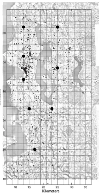
Ap´os a implementac¸˜ao do prot´otipo de middleware pass´amos ent˜ao `a fase de avaliac¸˜ao. Para esta fase de avaliac¸˜ao comec¸´amos em primeiro lugar, por procurar dois padr˜oes de mobilidade de ve´ıculos em ambientes urbanos. Estes padr˜oes servem para ser aplicados no simulador de rede de forma a criar um movimento realista e relevante para as nossas simulac¸˜oes. Os cen´arios escolhidos foram: um conjunto de posic¸˜oes de GPS de m´ultiplos t´axis na cidade de Roma e tamb´em o registo de posic¸˜oes de GPS para uma rede de transportes de autocarro na zona urbana de Seattle. Apesar de haver algumas diferenc¸as relevantes entre estes dois padr˜oes, como por exemplo a dimens˜ao total do cen´ario, esta mesma descrepˆancia entre eles serve para avaliar o middleware em diferentes ambientes. Escolhidos ent˜ao estes padr˜oes foi desenhado um plano para os testes. De forma a criar alguma relevˆancia estat´ıstica foi feita uma bateria de simulac¸˜oes sobre o middleware, sendo no total efectuadas 480 simulac¸˜oes. Com os resultados destas simulac¸˜oes, dos quais foram extra´ıdos valores como taxa de entrega e latˆencia de entrega, foram utilizadas algumas m´etricas relevantes para fazer uma avaliac¸˜ao. Usando gr´aficos gerados, foi poss´ıvel efetuar uma discuss˜ao da eficiˆencia do middleware podendo avaliar certas situac¸˜oes nas quais determinadas caracter´ısticas se sobressa´ıram. No entanto ficou claro que ´e ainda necess´ario fazer uma avaliac¸˜ao muito mais extensa de todo o trabalho dado a complexidade inerente
aos m´ultiplos parametros que existem no middleware, que sendo dispostos em diferentes configurac¸˜oes podem apresentar resultados muito d´ıspares.
Por fim, foram tiradas algumas conclus˜oes do que foi feito e das limitac¸˜oes que atualmente apresenta. Nesta conclus˜ao foi revisto se os objectivos que inicialmente se propˆos foram de alguma forma cumpridos. Foi tamb´em discutido algum trabalho que pode vir a ser feito no futuro. Este trabalho futuro apresenta algumas funcionalidades que melhoram a eficiˆencia e usabilidade do middleware. Um exemplo ´e o enriquecimento da semˆantico do espac¸o de tuplos utilizado que permitir´a ao utilizador efectuar mais facilmente pesquisas de tuplos com um esforc¸o mais reduzido.
Palavras-chave: Computac¸˜ao ub´ıqua, redes m´oveis ad hoc, middleware, espac¸o de tuplos e redes de sensores sem fios.
Abstract
This document focuses on the work done on the master thesis at the Informatics Department in the Faculdade de Ciˆencias da Universidade de Lisboa. With this work we aim at offering a reliable middleware that is capable of supporting data dissemination in a network composed of different types of hardware. Mainly these different components are sensors and mobile devices. We hope to offer a solution that is deployable in scenarios that have an high degree of heterogeneity without compromising the quality of service and functionalities of the applications used with the middleware. With these type of proposal we expect to cover many cases of ubiquitous computing such as the ones we find in smart cities scenarios.
Although our solution is aiming to be as generic as possible we take a practical case into account in order to provide a working example of our work. We take advantage of the infrastructure now available in some cities such as a mobile ad hoc network composed of public service vehicles. Doing so we will use our work in a garbage collection project where sensors read data from garbage cans in order to inform a set of base stations of their garbage levels. With this we allow the optimization of garbage collection in the future. Also by testing our middleware in this scenario we intend to gather more information that may allow for future improvements in the middleware.
So far we were able to implement a working prototype simulation designed for the Network Simulator 3. In this simulation we used some mobility patterns and tested the middleware in order to achieve results on its delivery rate and other metrics.
By perusing previous work done in studied areas of research such as tuple spaces and wireless sensor networks, we were able improve our concept. As a goal we look forward to create a piece of software that contributes to the community, making ease the process of going about our routines, work and the way we live in a more automated and pleasant smart city.
Keywords: Ubiquitous computing, mobile ad hoc networks, middleware, tuple space and wireless sensor network.
Contents
List of Figures xiii
1 Introduction 1 1.1 Motivation . . . 1 1.2 Objectives . . . 2 1.3 Contributions . . . 3 1.4 Document Structure . . . 3 2 Related Work 5 2.1 Tuple Spaces . . . 6
2.2 Delay Tolerant Networks . . . 7
2.3 Gossip . . . 8
2.4 WSNs Application Deployment . . . 9
2.5 Smart Cities . . . 10
2.6 Network Simulators . . . 10
3 System Model 11 4 A Delay-Tolerant Protocol for Smart Cities 15 4.1 Tuple Semantics . . . 15
4.2 Tuple Spaces . . . 17
4.3 Tuple Spaces Synchronization . . . 17
4.4 Code Deployment and Parametrization . . . 18
4.5 Communication Protocols Description . . . 18
4.5.1 Sensor on MANET Node Communication Protocol . . . 21
4.5.2 MANET Node On Node Communication Protocol . . . 22
4.5.3 MANET Node On Base Station Communication Protocol . . . . 22
5 Implementation 23 5.1 ns-3 . . . 23
5.2 Implementation Notes . . . 24 xi
6 Evaluation 27
6.1 Evaluation Metrics . . . 27
6.2 Parameters . . . 29
6.3 Mobility Patterns . . . 32
6.4 Results & Discussion . . . 33
7 Conclusion 43
Bibliography 49
List of Figures
3.1 Overall system groups and interactions between them. . . 12
4.1 Common header. . . 19
4.2 Data type payload. . . 19
4.3 Param type payload. . . 19
4.4 Code type payload. . . 19
4.5 Beacon, control and ack type payload. . . 20
4.6 Generic type payload. . . 20
4.7 Data type with priority payload. . . 20
4.8 Sensor and MANET node communication protocol. . . 21
4.9 Intermediate node on node communication protocol. . . 22
4.10 Intermediate node on base station communication protocol. . . 22
5.1 Software organization of ns-3. . . 24
5.2 UDP Fragmentation . . . 25
5.3 UDP Unfragmentation . . . 26
6.1 Rome and Seattle mobility pattern areas. . . 33
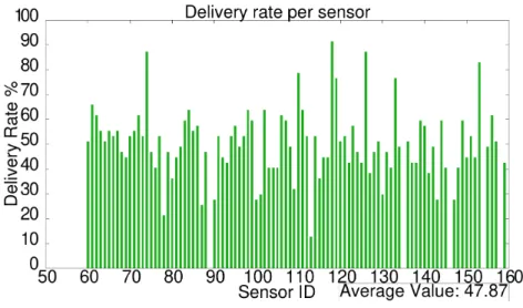
6.2 The delivery rate of each sensor. . . 34
6.3 The number of contacs per sensor. . . 34
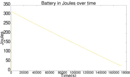
6.4 The remaining capacity of all the batteries over a time. . . 35
6.5 Message delivery per epoch. . . 35
6.6 Message delivery over time. . . 36
6.7 Fanout variation effects on the delivery rate. . . 37
6.8 Fanout variation effects of the latency. . . 38
6.9 Sleep time variation effect on the delivery rate. . . 39
6.10 Sleep time variation effect on the latency. . . 40
6.11 Sleep time variation effect on the remaining battery capacity. . . 41
6.12 Number of MANET nodes effect on delivery rate. . . 41
6.13 Number of MANET nodes effect on latency. . . 42
List of Tables
3.1 Mobility versus Resources . . . 12
4.1 Message Types. . . 19
4.2 Reading Types. . . 20
6.1 Default configuration file in the simulations. . . 31
Chapter 1
Introduction
1.1
Motivation
Many cities and urban areas are trying to transform themselves into smart cities, in an effort to improve the quality of life of its citizens. This work aims to develop a generic framework for IoT so that it can be deployed in a number of scenarios envisioned for smart cities. Nonetheless we take into account one practical case that will help us experiment and define a more refined model. We can define the case scenario for this work as a smart city where garbage collection can be improved. Garbage bins are deployed in a widespread area and can get full and stay full for some time. This situation has a bad visual effect and raises public health issues. The work done by city councils and garbage collection companies is not easy as it is challenging to predict when and where a garbage bin will need to be collected. Fortunately, to solve this problem one can deploy sensors that are able to measure garbage levels in each bin, and afterwards use the data produced to optimise the garbage collection process. By collecting several fullness level readings it is possible to understand how the waste grows in several areas and define new garbage truck routes in run-time, saving fuel and avoiding unnecessary detours.
To reduce communication costs, the framework leverages on city vehicles such as police cars, fire trucks, ambulances or even garbage trucks themselves as communication media to deliver the data produced by the sensors, alleviating the network infrastructure and extending the devices battery lifetime. Benefits emerge from the use of short range communications protocols, in contrast with infrastructure communication channels that have great impact on the battery usage.
This application is abstracted in a model where several different components with distinct characteristics must communicate small amounts of data with an high frequency to a sink node. These components are mainly sensors and mobile agents. With this premise, many messages have to be exchanged between participants and several contacts have to be established. However message passing is costly for the sensors as they depend on a battery with limited capacity. Preserving battery is an important objective, as it allows for a longer
Chapter 1. Introduction 2
lifetime of the sensors inside the network, reducing maintenance frequency and costs. In spite of battery saving concerns it is also important to perform the timely delivery of the data produced by the sensors without decreasing significantly the delivery rate. With our proposal we intend to offer a dependable solution for this issues that takes advantage of the surrounding infrastructure and environment.
The solution reported in this work consists of splitting the above mentioned components into three modules which are integrated into a middleware supporting communication among them. The first module is composed of resource constrained sensors that are able to perform readings and transmit the data. The second module is composed by nodes with high mobility and plentiful of resources that allow for the dissemination of the data produced by the first module. Finally the last module is described as stationary and resourceful, where the data must be delivered and processed. This partition permits to define a specific behaviour in a way that creates a flow of data between the modules by assigning specific roles for each of the components.
The middleware is inspired by a tuple spaced based communication model for DTNs (Delay Tolerant Networks). Tuple spaces define a common format as well as anotations that facilitate communication. Our model also contemplates priority requirements that define how a sensor can behave, such as quality of service or energy costs, permitting the use of more costly communication media in some cases and bidirectional messages to support sensor reconfiguration.
1.2
Objectives
The overall objective of this work consists in devising and evaluating a framework to collect and pass data from sources to sinks in a urban scenario using heterogeneous devices and sensors. To achieve this goal, we developed a middleware framework that aims to fulfil the following:
• Implement a tuple space solution for DTNs that can be used by the several compo-nents of the network to pass data to each other;
• Create the semantics for the communication between sensors and sinks, allowing the use of some patterns in order to filter specific data;
• Develop a routing strategy capable of spreading data even when the number of messages traded between the participants is large;
• Create an API that offers the possibility of code deployment and different configura-tions regarding the sensor resources;
Chapter 1. Introduction 3
• Perform an evaluation of the work in order to understand its limitations and capabili-ties.
1.3
Contributions
This work provides the following contributions:
• A middleware capable of easing the data flow in networks characterized by their high mobility and dynamic connections;
• Improve the automatic processing in smart cities in order to make them more efficient thus contributing for an improved quality of life;
• A study on the efficiency of the message passing solution developed.
1.4
Document Structure
This document is structured according to the following schema:
• Chapter 2 – Related Work: this chapter comprises a set of previous research that is in relation to this work and somehow has some influence in the way our research was conducted and designed. We also present some important base concepts relevant to the solution;
• Chapter 3 – System Model: were the analysis and requirements for the work are exposed in a description of the problem;
• Chapter 4 – A Delay-Tolerant Protocol for Smart Cities: in this section a description of the solution for the problem is presented with some detail;
• Chapter 5 – Implementation: details about the implementation of the work are described in this section as well as some information about the technology used; • Chapter 6 – Evaluation: a chapter were the results of the work are discussed in depth
and an overall evaluation of the middleware efficiency and usability is presented; • Chapter 7 – Conclusion: contains a final discussion about the overall work were
Chapter 2
Related Work
The diversity of IoT devices has been increasing, providing an ever growing number of services, from fixed sensors, that are able to perform measurements, to mobile devices with powerful processing power. These devices can be arranged in groups and specific patterns and form interesting systems to spread data around an widespread area. Cities try to use their infrastructure alongside with these devices in order to increase automation and increase the quality of life.
Two important networking models typically associated with these devices are mobile ad hoc networks (MANET) and wireless sensor networks (WSNs). A MANET is a network composed of mobile nodes each with its independent movement. Connections between these nodes are opportunistic and so MANETs can be described as a highly dynamic network. This type of network typically uses strategies such as flooding or some type of controlled flooding. Flooding is a type of message diffusion in which the message is delivered to all possible nodes in order to make it arrive to its destination as soon as possible [6].
WSNs are composed of several independent sensors distributed over a geographical area. Sensors communicate between them and cooperatively try to send data to a specific point (sink). These networks can scale to a very large number of devices [1].
Also in relevance to this work are the delay/disrupt tolerant networks (DTNs). A delay tolerant network is characterized by a lack of continuous connectivity. In an environment such as this, the delay in delivering a message can be sometimes measured in hours or days. To support this type of communication the nodes of the network are required to be able to store the data until it can be delivered to the destination or propagated to other nodes. In many scenarios the connectivity patterns are very difficult to predict and whenever a connection is established it can have a very low bandwidth. An example of this type of networks is space exploration missions where a satellite roaming through space can only contact the ground control to send data a few times a year. This is due to resource restrictions and also by its environment and the absolute distance back to earth which may greatly increase the latency [5].
Chapter 2. Related Work 6
Lastly we introduce the concept of Publish/Subscribe. In this model there are two main entities, the publishers and the subscribers. The publishers are the content creators. In topic based publish/subscribe publishers associate each message to a specific topic. On the other hand the subscribers subscribe to a specific topic and get notified each time some message with that topic is created. This communication is done asynchronously. Besides topic based subscription there are also other types, of which the content based is also worth mentioning. In content based messages are delivered to the subscribers if the attributes or the content of a message match constraints defined by the subscriber [6].
After this brief introduction of concepts we now take a look of some more detailed work about certain topics related to our work.
2.1
Tuple Spaces
Huge delay and sparse connectivity are problems that are expected in networks such as MANETs and DTNs, so asynchronous communication is an important aspect that must be supported by the middleware. In the matter of data sharing we take a look at the tuple spaces paradigm and some previous work done in the area.
Tuple spaces were first introduced by Linda [2] as a paradigm for parallel computing. Unlike many other models, Linda doesn’t use message passing or shared variables to allow processes to communicate with each other. Instead it uses a data object called tuple and it shares them in an abstraction named tuple space. A tuple is a finite unordered list of elements. Tuple spaces allow for a high decoupling of the processes involved, meaning that two or more processes can communicate without the need of knowing each other directly or even synchronously. Linda offers a simple set of operations: eval, out, in, rd. The out operation is used to generate a new tuple and place it in the tuple space. The in reads a tuple and removes it from the tuple space whilst the rd does the same without removing it. In Linda, both in and rd operations block the process until one tuple matching the read/in passed as an argument is found on the tuple space. In order to perform the in and rd operation a formal/actual tuple must be defined to perform the matching of the desired tuple. Formal tuples use wildcards in its fields as to expand the range of possible matches. Taking the following tuple as an example:
<” a s t r i n g ” , ? f l o a t , ? i n t e g e r , ” a n o t h e r s t r i n g ”>
Executing a in with this tuple will search for a tuple that shares the exact same string in the first and last field and has the same types of the second and third fields. On the other hand actual tuples represent a specific tuple with real values. In their case no wildcards are allowed. An example of an actual tuple is presented below:
Chapter 2. Related Work 7
Linda was designed to offer an alternative to other parallel programming models to distributed systems. As an alternative L2imbo [3] came forward as an important platform
due to its connectionless programming platform paradigm and a uniform architecture for QoS control and monitoring. This is achieved by adding deadlines to tuples. By doing so, an out operation includes a lifetime defining the time the tuple can reside in the tuple space. The deadlines can also be applied to the in and rd operations which allows to have time-out operations without having to create the inp and rdp primitives. Furthermore by applying QoS monitoring agents it is possible to track key aspects of the system. E.g. two typical forms of QoS agents that can be used in L2imbo are the connectivity and cost monitors. The first allows to watch over the characteristics of the infrastructure whilst the second is able to determine the cost associated with the current communication link.
Another important change was the possibility to create multiple tuple spaces. Origi-nally, Linda was designed to support parallel programming featuring a single tuple space. This adaptation provides means to address issues such as performance, partitioning and scalability. In order to create multiple tuples spaces, clients use the out operation to the universal/global tuple space, which serves as a control center, indicating that they want to create a tuple space and its characteristics. Besides this there are also use, discard and terminate primitives that allow for a more complex usage of this tuple space model and even allow recursively creating more tuple spaces over each other. Although this was one important advance in the tuple space paradigm regarding nodes with mobility, the model used by L2imbo is nomadic and still requires some sort of base station or static node.
Lime [4](Linda in a mobile environment) is also based on Linda although it assumes a MANET mobility model to allow the use of tuple spaces in a more dynamic and unpredictable scenario. Lime authors notion of communication links also take into account several aspects such as host departure due to mobility that enable an efficient tuple trading in more resilient scenarios.
2.2
Delay Tolerant Networks
A DTN (Delay Tolerant Network) is a type of network that is designed specifically to address situations where the connectivity between nodes changes often. Occasionally, this type of networks can experience partitions for an indefinite amount of time due to their characteristics such as low number of contacts and high delay. Contacts can be defined as connections established between nodes whenever possible due to physical characteristics. This type of properties makes DTNs an interesting and challenging class of networks. Since many of the contacts are opportunistic and sometimes it is hard to know when and where a contact will occur, routing can become a complex problem. For this type of problems, the store-and-forward technique is employed. In most cases, routing is done dynamically and reactively, meaning that the path for the routing is defined as the message
Chapter 2. Related Work 8
travels through the network. Besides this, DTNs are supported by many devices that have strict resource limits and managing them efficiently also becomes a problem.
The knowledge about the network can be very helpful in routing. E. g. knowing the mobility pattern of a node contributes to optimise whenever the other communication node should expect a connection. A complex study of this type of influences is presented in papers such as Jain et al. [5]. This presents several types of knowledge oracles, each capable of withholding different types of information, two delay tolerant scenarios (remote village and city bus lines) and several protocols that take advantage of these oracles. The results show that having more knowledge increases the overall performance of the routing.
Considering these types of knowledge it is possible to split awareness into categories as it is described by Garbinato et al. [6]. The first is Context-Oblivious Routing where there is no knowledge about any possible path to route. For this type of situation, approaches such as flooding and disseminating the message as widely as possible are the most common practices. The second is Partially Context-Aware Routing. In this category algorithms exploit some piece of context as a way of optimising their routing. For this case many of the algorithms are customised for a specific type of context information. Lastly there is Fully Context-Aware Routing that exploit all the context information and besides this also provides mechanisms to handle and use context information.
2.3
Gossip
Gossip is a network broadcast communication protocol that relies on probabilities to disseminate data. It is characterized by the repeated probabilistic exchange of data between nodes. By having this probabilistic component it means that the communication partners are chosen in a non-deterministic way. Also by definition gossip is intended to be repeated endlessly.
Whenever a node has to broadcast a message it chooses a set of t nodes (where t is called fanout) from its know collection of contacts and only propagates the message to that set. When node receives a message for the first time it stores it in a buffer. In this buffer there is a ∆ time in which a node remembers a message in order to do gossip it. The buffer contains all messages to be gossiped in each protocol round. If a node receives the same message twice it is discarded. Usually the fanout is taken randomly as a way of increasing the probability of spreading the data to different nodes each time a message has to be broadcasted and retransmitted. This type of protocols tend to perform well in distributed systems were they ensure high scalability and reliability [7].
One of the first papers to present a formal definition for gossip is the Epidemic Algorithms for Replicated Database Maintenance [8]. The paper uses a complex epidemic mechanic mixing three methods: the direct mail, anti-entropy and rumour mongering. Direct mail can be roughly summed up to attempting to notify all other know connections
Chapter 2. Related Work 9
when update. Rumour mongering consists of branding new updates as ”hot rumours” and whenever a node has one it takes periodic cycles to spread that information to other nodes chosen randomly. Finally anti-entropy is the act of regularly choosing another node to exchange its database contents. This is used as a way of achieving consistency in a very reliable way, although it is a very slow method to employ and cannot be used as frequently as the other two methods. The rumour mongering and the anti-entropy methods are both examples of epidemic processes, that are used together to form a complex epidemic protocol.
Another interesting example is Pbcast (Probabilistic Broadcast) [9] that is designed mainly for voting-style protocols, e.g. database quorum protocols. In this protocol, whenever a process/node desires to initiate a vote it sends a message to a random set of other processes and each of them randomly propagates to another set of members. It uses a fixed number of rounds in which each process participates in at most one round. Additionally processes choose their gossip target by tossing a weighted random coin for each other possible destination.
The gossip protocols presented so far weren’t conceived to support mobile networks. However, Gossip can also be applied as a diffusion mechanism for these networks. An ex-ample, is the work done in ”A Socio-Aware Overlay for Publish/Subscribe Communication in Delay Tolerant Networks” [10], where the notion of gossip is used together with delay tolerant networks. The paper uses gossip as a form of community/membership detection that helps to support their Socio-Aware Overlay using the publish/subscribe paradigm.
2.4
WSNs Application Deployment
One important feature for WSNs is the capability of deploying and updating applications after the sensors have been deployed with the smallest cost possible. Ideally, sensors should also be able to accept remote configuration and to adapt behaviour of those applications without having to physically access each sensor as doing so is practically impossible.
Agilla [11] emerged as a flexible solution to those problems. By adopting a mobile agent-based paradigm, Agilla allows for agents to migrate across nodes in a dynamic and intelligent way as each agent works as a virtual machine with dedicated instructions and its own data memory. Agilla presents itself as a platform that simplifies the way that WSN applications are developed by allowing for developers to write software in a higher-level language that is able to migrate between nodes. Agilla uses tuple spaces to coordinate the several agents and access physical resources. With our middleware we hope to enhance this concept a little bit further by employing the usage of other networks (MANET). In contrast to the previous example we aim to extend the range of transmission of the data produced as we use a complementary network to support the wireless sensor network in its data dissemination.
Chapter 2. Related Work 10
2.5
Smart Cities
By looking at the following examples we can see that most smart cities of nowadays use many Iot devices and networks such as MANETs and together they can form interesting solutions. Although there are many examples we consider that there are many more possibilities yet to be explored and the field is still going to advance much further in the future. Ribeiro et al. [12] recently presented a survey of public transport routes of users of a bus transportation system. By placing several RaspberryPi devices on the buses and taking advantage of the several access points that each bus carries, the authors were able to gather enough data to create several Origin Destination (OD) matrices that allowed them to understand where people got in and off the bus and thus optimising bus routes in the future. Sim˜oes et al. [13] also exploits the usage of unmanned aerial vehicles (UAV) to assist in case of any emergency and Li et al. [14] proposes the usage of vehicle to vehicle technology and its infrastructure to synchronize traffic lights. By taking a close look at specific traffic patterns and also taking concern in dynamic changes such as peak hours in traffic they are able do draw a system model. With this model they afterwards apply an hybrid genetic algorithm that is to offer an optimization solution that adapts dynamically whenever the traffic decreases or increases.
2.6
Network Simulators
Network simulators have an important role in the area since they enable the execution of experiments that otherwise would be very hard to do due to their scale and complexity. The most relevant for this work is the ns-3 [15] that offers a collection of modules to create different types of simulations. The modules vary from internet appliances to energy management or mobility. By offering all these modules and many other features, ns-3 became quite popular in the community as well as his predecessor NS-2. Networks simulators are an important part of the work done in this report. They allow for the execution of big scale tests that help collect data to measure the performance of the middleware without the difficulties and costs involved in the deployment of large scale testbeds.
Chapter 3
System Model
The system model assumes a network widespread over a urban area, composed of devices with different characteristics and limitations. According to their role and behaviour devices can be arranged in three groups, a group of sensor nodes distributed over a geographical area, a mobile ad hoc network (MANET) and a group of base stations where the data produced by the sensors must be delivered.
The sensor network is where the requirements are most restrictive since there are many resource constraints due to the nature of the hardware deployed. Battery life, processing capabilities, storage and communication range are considered to be minimal and must be always taken into account throughout the lifetime of the system. Sensors are expected to remain static most of the time and only experiencing small displacements with low but unknown frequency. They are also expected to communicate using at least one of the following wireless technologies, Zigbee, Wifi, Sigfox or 3G/4G. Considering battery consumption and cost, the latest options are reserved for scenarios deemed critical where the data must be sent as quickly as possible to a sink station. Sensors are expected to collect data and send it as soon as possible using shorter ranges and lower power networks. To accomplish this any node in the network can use the MANET to disseminate data.
Requirements for the MANET are somewhat more relaxed since it is expected that mobile nodes have a substantial amount of resources and can easily withhold larger amounts of data. Each of these nodes is considered mobile and capable of passing through several sensors and other mobile nodes many times a day, although no assumptions on their movement patterns is. Their communication is also expected to be done using wireless radio and their primary purpose is to forward the data to the base stations in a timely and reliable manner.
The base stations or sinks are static nodes that expect to receive data from the MANET at anytime and aggregate that data for further processing. They interact with the MANET nodes at well known ”delivery points”. They have no resource restrictions and are designed to be the endpoint of the data arriving from sensors. The relations between the mobility and resources of each group is presented in Table 3.1.
Chapter 3. System Model 12
Resources
Low High
Mobility
Low Sensor Network Base Stations
High - MANET
Table 3.1: Mobility versus Resources
The scenario fits nicely into the characteristics of a delay tolerant network. Regarding the sensors, an API will allow to program them so that their behaviour can adapt to several resource scenarios and also adjust the way they manage their resources as its availability varies. This is done by using heuristics that with a local energy model can determine how to behave. Besides this, the API will also allow for run-time code deployment (e.g. bugfixes) that can spread to all sensors or groups of sensors. Sensors can have different roles. In smart cities scenarios, for example, some sensors can detect traffic behaviour and others weather conditions. Multicast groups can be defined within the network and apply changes and configurations to specific groups of sensors. Code deployment is done in the inverse direction of the data flow produced by the data sources, thus the code deployment changes travel from the base station to the MANET and are eventually delivered to the sensors.
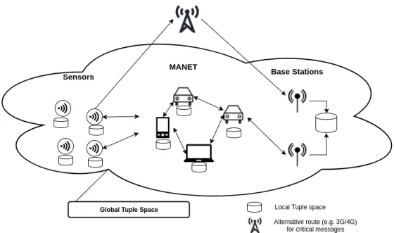
Figure 3.1: Overall system groups and interactions between them.
Communication leverages on the tuple spaces paradigm, using Linda [2] like semantics. For instance sensors will apply an out operation to send a tuple with data to the MANET and base stations will perform the in operation using a template to receive the data produced
Chapter 3. System Model 13
by the sensors. During the data flow in the MANET several in and out operations will also be performed as each node exchanges tuples with another node. Figure 3.1 depicts all the three groups forming the global tuple space. Each of the nodes in those groups has a local view of the data, with its own local tuple space. While the sensors produce data and the MANET deliver it, the base stations will form a more complete view of the system as they try to hold a history of all the data produced by the sensors.
Chapter 4
A Delay-Tolerant Protocol for Smart
Cities
The design of the whole solution evolves around the idea of forming a global tuple space that comprises the sensors, the nodes and the base stations. Each of these will have a local tuple space. Participants share and exchange with each other in order to spread the data. We will also employ some strategies to perform garbage collection to remove stale tuples in the network (content that is no longer in need to be diffused) and the possibility of performing code redeployment and changes in the configuration.
4.1
Tuple Semantics
The framework honours Linda tuple definition [2], supporting tuples of any form and with undefined number of fields. However, to benefit from all its capabilities, in particular, garbage collection of old tuples, some specific predefined structures are required. This main structure is used for sharing data and is composed of the following elements:
<messageType , ID , epoch , c o u n t e r , typeMask , v a l u e , t i m e s t a m p > • messageType - defines the type of the message, which must be one of the following
possibilities:
data – used for carrying data;
control – used as customizable tuples for controlling garbage collection;
param – contains a specific value for a parameter to change the sensor behaviour; code – used to inform that the tuple contains a code update;
beacon – used to inform that a node is nearby; ack – represents the acceptance of a message;
Chapter 4. A Delay-Tolerant Protocol for Smart Cities 16
generic – any other possible tuple. • ID – unique node identifier;
• epoch – implementation of the garbage collection mechanism; • counter – implementation of the garbage collection mechanism; • typeMask – data type of value (see Table 4.2);
• value – the value in the tuple;
• timestamp – the creation date of the tuple.
An example of a tuples definition is given below:
<” d a t a ” , 0 0 : 0 0 : 0 0 : 0 0 : 0 1 , 1 , 2 1 , ” t e m p e r a t u r e ” , 2 . 3 f , 28342> In the first tuple, the first field represents a data reading, the second indicates that the data source unique ID (MAC address) of ”00:00:00:00:01”, the third expresses that the current epoch is 1, the fourth field indicates the a unique counter (see Section 4.3) used for garbage collections purposes, the fifth field means that the tuple contains a float and the last two fields contain the data value and a UNIX timestamp. In contrast with the remaining message types, code tuples only have five fields, being the first the ”code” message type, the second the sensor ID, the third and forth the current epoch number and code version and lastly the snippet of code. The tuple structure is as follows:
<” c o d e ” , ID , epoch , c o d e V e r s i o n , ” c o d e S n i p p e t ”> An example is given below:
<” c o d e ” , ” 0 0 : 0 0 : 0 0 : 0 0 : 0 1 ” , 1 , 2 , . . . >
To perform an in operation one can use a formal tuple and wildcards to catch specific data. For instance to get all tuples that contain readings from the sensor with a specific sensorID (second tuple field) the following formal tuple will suffice only defining the type and ID and using wildcards on all the other fields:
Chapter 4. A Delay-Tolerant Protocol for Smart Cities 17
4.2
Tuple Spaces
Each element in the network will possess a local tuple space interface that offers the possibility of storing tuples locally. The local interface offers all the basic tuple operations such as in and rd. Each one of these local tuple spaces holds a small set of the all the tuples in the network forming together the global tuple space. The way each one of these tuple spaces trades messages and achieve an overall consistency is discussed in section 4.3.
4.3
Tuple Spaces Synchronization
In an effort to populate the global tuple space with the data from each local one, sensors attempt to forward their local tuple space to any passing by MANET node. Each of those nodes will attempt to retransmit the received data to any other possible node to increase the probability of having them delivered to a base station. Synchronization is triggered by participants receiving the beacon type tuples broadcasted by other nodes. However, to save sensor resources only the MANET nodes broadcast beacons. Besides this, sensors in a resource saving fashion vary between two possible states. Either they are sleeping or they are idle listening for a beacon.
Synchronization is inspired in the gossip communication approach [7]. Whenever each MANET node has to retransmit its tuples, we use an adjusted notion of fanout to select a small set of tuples to be sent instead of selecting the gossip target nodes. On the other hand we perform a broadcast to all possible nodes instead of a small set of targets as done traditionally in gossip. This technique is useful to limit the number of duplicate tuples in the global tuple space. Additionally, tuples are equipped with a sequence number unique to each sensor. This sequence number is composed by three elements: the sensor ID, the epoch number and the counter. It is possible to cross these three elements to identify a tuple uniquely. Whenever a MANET node receives a tuple that has the same sequence number it is able to discard it thus avoiding unnecessary tuple copies.
A side effect of this model is the decreased efficiency of the middleware. If the global tuple space contains too many tuples, they can be spread perpetually thus provoking a retransmission of futile stale tuples that have been already delivered to a base station. Without a garbage collection mechanism the uncontrolled conveyance of data might render the network useless due to the amounts of stale data that it stores.
Epochs impose an expiration date on tuples. The epoch number defines in which epoch the message was produced and the counter grows monotonically within each epoch. Periodically, the base station increments the epoch number, which becomes propagated by the beacons advertised by the participants.
To implement garbage collection, the middleware dictates: i) that all participants are required to tag the tuples they create with the highest epoch number observed; and ii)
Chapter 4. A Delay-Tolerant Protocol for Smart Cities 18
purge their local tuple space from tuples created E or more epochs beyond, with E being a configurable parameter that can be adapted to the observed networking performance. The efficiency of this result depends directly on the epoch duration. By using this method it is possible to ensure that eventually all old tuples will be discarded from the MANET.
Synchronization between the sensor’s local tuple spaces is not supported. As a sensor starts to perform readings it stores its tuples locally until it is able to dispatch them. To do so it uses two alternatives, either it sends them to one of the nodes in the MANET as soon at it establishes contact or it uses a more expensive protocol (Sigfox or 3G/4G) to send it directly to the base station. The latter solution is reserved for tuples with priority and is used at the expense of more resources but offers much less latency. For both the situations, a simple rd operation is used to pass the tuple and afterwards discarding locally the data.
Base stations receive data from the MANET or directly from a sensor. In the base stations the bulk of the data is stored allowing for a further and extensive data analysis.
4.4
Code Deployment and Parametrization
The platform allows for code deployment and parameters to be passed to the application using special tuples. In order to receive them the sensors will perform rd operations to any tuple containing either ”code” or ”param” messageType. Being sent from the base stations these tuples will be carried by the MANET in order to reach the sensors and spread the desired reconfigurations. If a tuple contains the ”param” type it will represent a parametrization to be applied to the application. Upon receiving it, each sensor changes its behaviour to comply with the new parameter value. If the message type is ”code” a new snippet of code will be deployed at every sensor and change its routine. This snippet is passed in the tuple as a string of bytes. Each sensor upon receiving a new snippet of code will try to perform a hot swapping of the code. In case the code has compilation problems the changes will not be performed and the sensor will continue to run as normal. Although this last part regarding the compiling of the code and hot swapping is not yet fully implemented it is intended to be developed as future work.
4.5
Communication Protocols Description
In order to allow the different participants of the middleware to communicate between them we designed a few simple protocols for each interaction. Between them they also use different types of messages each with its unique way of serializing.
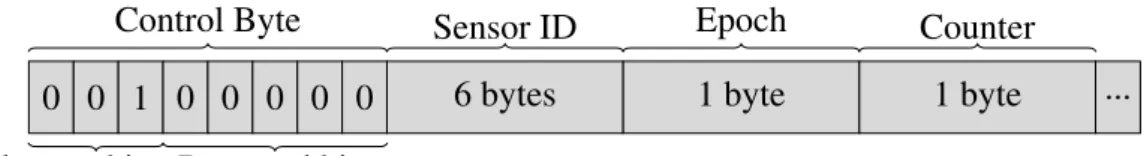
Most messages will share a common header. This header has a size of 9 bytes and it is formed as depicted in Figure 4.1:
The first three bits of the header form a mask that indicates the message type. There are seven possible message types. The type definition is presented in the Table 4.1.
Chapter 4. A Delay-Tolerant Protocol for Smart Cities 19
0 0 1 0 0 0 0 0 6 bytes 1 byte 1 byte ...
Control Byte Sensor ID Epoch Counter
Tuple type bits Reserved bits
Figure 4.1: Common header. tuple Type bits
data 0 0 0 control 0 0 1 param 0 1 0 code 0 1 1 beacon 1 0 0 ack 1 0 1 generic 1 1 0 Table 4.1: Message Types.
The last five bits of the first byte are reserved for future use. The next six bytes are used to store the sensor ID (e.g. mac address) and the last two bytes of the header store the epoch and counter.
The payload for each message type is structured according to the schemas depicted in Figure 4.2 to 4.6:
Common Header 1 byte mask int or float or string 4 bytes
Reading Type Date
Figure 4.2: Data type payload.
Common Header 1 byte mask int or float or string Reading type
Figure 4.3: Param type payload.
Common Header code binary Figure 4.4: Code type payload.
Chapter 4. A Delay-Tolerant Protocol for Smart Cities 20
Common Header
Figure 4.5: Beacon, control and ack type payload.
Common Header 1 byte mask int or float or string ... Reading type
Figure 4.6: Generic type payload.
Whenever a tuple is marked with priority there is only one possible serialization and to comply with the message size dictated by sigfox, which is 12 bytes we only allow for the epoch of the message, the message counter and the value and its type to be passed due to bandwidth restrictions. The value can only be up to 4 bytes.
1 byte 1 byte mask 1 byte mask at most 4 bytes
Epoch Counter Reading type
Figure 4.7: Data type with priority payload.
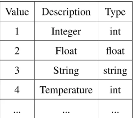
Value Description Type
1 Integer int
2 Float float
3 String string
4 Temperature int
... ... ...
Table 4.2: Reading Types.
The reading types define the value type as shown in Table 4.2. By default we offer three types that correspond to an integer, float or string but up to 32767 distinct types can be defined, permitting to associate some semantic to this tuple. For the given example a new type with the description ”Temperature” was defined and associated to the reading type 4.
Chapter 4. A Delay-Tolerant Protocol for Smart Cities 21
4.5.1
Sensor on MANET Node Communication Protocol
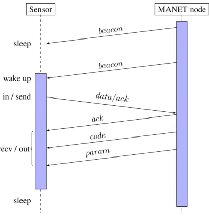
This protocol is designed to allow the communication between the sensors group and the MANET node group and behaves as follows. As a MANET node moves, it frequently broadcasts a beacon message in order to announce its presence to other nodes or sensors. If a sensor is awake and manages to receive this message it will initiate an exchange with the MANET node. It initially performs an in operation of its data tuples and sends them to the MANET node. If it receives back an ack message it then discards the tuples, otherwise it puts them back in the tuple space. In case it has no data to send to the MANET nodes it sends an ack message so that the other end might proceed with the protocol. After this transaction, the sensors receive possible code changes and parameters. The epoch is carried in every message header, so whenever a sensor receives a beacon it is able to update is epoch. Figure 4.8 illustrates the protocol described.
Sensor MANET node
sleep wake up in / send sleep beacon beacon data/ack ack code param recv / out
Chapter 4. A Delay-Tolerant Protocol for Smart Cities 22
4.5.2
MANET Node On Node Communication Protocol
When two MANET nodes get in contact with each other they synchronize their tuple spaces. When a node receives a beacon message from another node it sends back an ack message and so the first node sends its data, code and param tuples. The latest epoch (known by the node) is also sent in the beacon message thus allowing both nodes to update their epoch counter. This protocol is also executed in the inverse way since the other node also sends a beacon message and so the protocol is initiated by both nodes. Figure 4.9 illustrates the protocol described.
Intermediate node 1 Intermediate node 2 beacon
ack data code param
Figure 4.9: Intermediate node on node communication protocol.
4.5.3
MANET Node On Base Station Communication Protocol
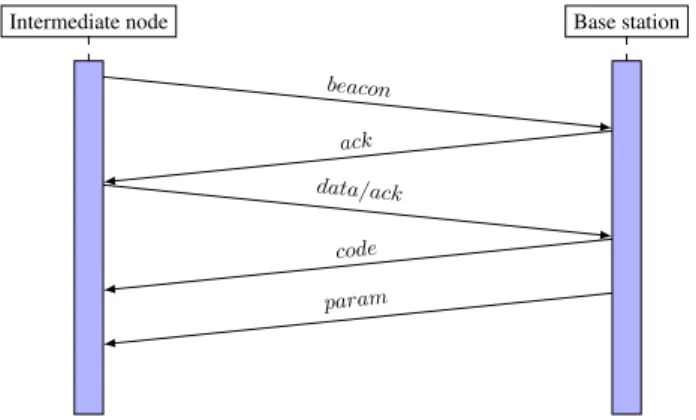
The exchange between an MANET node and a base station is similar to the one described in section 4.5.1 for sensor to MANET node communication. Upon receiving a beacon message the base station will send an ack to inform that it is ready to receive the data. Afterwards the node either sends its tuples or an ack to tell the sink it has no data to send. Finally the base station sends all its code and param tuples. Figure 4.10 illustrates the protocol described.
Intermediate node Base station beacon
ack data/ack
code param
Chapter 5
Implementation
In this chapter we approach two main implementation aspects. In the first section we discuss the usage of the ns-3 network simulator and the modules used to create an accurate simulation for the middleware. In the second chapter we present some small implemen-tation notes on pieces of software that we consider interesting and presented challenges during the creation of the middleware.
5.1
ns-3
ns-3 is a discrete event network simulator that allows for the creation of big and complex simulations. It is implemented mainly in C/C++ and Python thus allowing for the simu-lations to be written in both these languages. This middleware version for ns-3 (version 3.27) was written in C/C++. ns-3 consists of several modules each with its capabilities that cohesively allow for the whole simulation to be built. The bulk of the simulation was supported by the core, internet, network, propagation models and wifi models modules. With them as building blocks the behaviour of the three agents (sensor, MANET node and base station node) was built into the application module using the appropriate inheritance patterns in the classes offered by ns-3.
For the battery management, the ns-3 energy module was used with a LiIon energy source and a wifi radio energy model, that considers power consumption in several states (transmitting, receiving, idle and sleeping)[16]. To simulate the priority channel and given that there is no SigFox module in ns-3, the LTE Models module was used, communi-cating with the internet over a PGW server linked to several antennas. Regarding the mobility scenarios the ns-3/ns-2 mobility module loaded the several mobility patterns. BonnMotion[17] was used to generate the manhattan grid mobility scenario. Even tough this scenario was not used in the evaluation we considered it important as it allowed us to test the middleware in the earlier phases. NetAnim was used to view the generated simulations and the communication between the several nodes. For our evaluation we
Chapter 5. Implementation 24
simulated using a optimized build version of ns-3.
Figure 5.1: Software organization of ns-3.[18]
5.2
Implementation Notes
The data of each experiment was collected using custom tracer classes that wrote into files. This files contained the necessary information to track each event and associate it with a specific node and a specific timestamp. To process the data, bash and gnuplot [19] were used to create some relevant charts using the metrics defined in Section 6.1. The automation of the tests for the simulations was done using also bash to create scripts that performed the multiple runs required and automatically effected the variation between each step (see Chapter 6).
Several challenges arose while implementing the middleware. The first was the tuple serialization which required extensive use of bitwise operations and C lang primitives. This serialization has to be as fast and as effective as possible as it is widely used during the middleware lifetime.
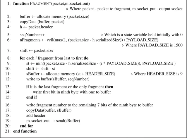
Another interesting challenge that emerged was the implementation of the packet fragmentation due to the UDP 65355 max byte size datagram. For this, we implemented a payload fragmentation layer that splits packets into 1500 bytes pieces and sends them over the network. On the receiving side this layer keeps tracks of each message and only delivers to the application after having all the required frames. This layer also keeps track of a possible timeout, for instance if a datagram is missing a part after a certain time it will be discarded as to avoid wasting unnecessary resources. This situation happens mostly with code tuples, which are considerably larger than the others.
In Figure 5.2 we show the algorithm for the UDP datagram defragmentation. In this algorithm we first start by copying the contents of the message into a buffer and we
Chapter 5. Implementation 25
1: function FRAGMENT(packet,m socket out)
. Where packet - packet to fragment, m socket put - output socket 2: buffer ← allocate memory (packet.size)
3: copyData (buffer, packet)
4: h ← packet.header
5: seqNumber++ . Which is a state variable held initially with 0
6: nFragments ← ceil(max(1, (packet.size - h.serializedSize)) / PAYLOAD SIZE)
. Where PAYLOAD SIZE is 1500 7: shift ← packet.size
8: for each i fragment from last to first do
9: st ← min((packet.size - h.serializedSize - (i * PAYLOAD SIZE)), PAYLOAD SIZE )
10: shift ← shift - st
11: sBuffer ← allocate memory (st + HEADER SIZE) . Where HEADER SIZE is 9
12: write to buffer(sBuffer, seqNumber)
13: if it is the last fragment or the only fragment then 14: write first bit in ninth byte with one to buffer
15: end if
16: write fragment number to the remaining 7 bits of the ninth byte to buffer
17: copyData(buffer, sBuffer)
18: add header
19: m socket out → send(sBuffer)
20: end for
21: end function
Figure 5.2: UDP Fragmentation
increase the number of sent messages in the fragmentation layer (line 2 to 5). Afterwards we calculate the number of 1500 bytes fragments to be sent (line 6). With this value we repeat for each fragment the same procedure, this is done from the last fragment to the first to reduce the number of memory allocations when receiving the message on the other end. The procedure consists in determining if the size to copy is 1500 or smaller (line 9) and then proceding with the filling of the buffer to send (sBuffer). In case it is the last fragment we write in the first bit of the ninth byte to work as a flag (line 13 to 15). Finally we fill the other 7 bits of the ninth byte with the fragment number and send the message over the socket.
Regarding the unfragmentation of the message we show the algorithm in Figure 5.3. Each time that the middleware receives a fragment it is required to verify if the whole message is complete before delivering it. First we start by allocating a buffer with the data from the fragment (line 3 to 4) and then we read the seqNumber of the message (line 5). Using the mac address of the source node and the seqNumber of the fragment we are able to build an unique key (line 6), this key is used to store and find each fragment in a memory structure (line 9). If the key is already in the structure it means that we have a record of the message but it is still wanting on more fragments before it can be delivered.
Chapter 5. Implementation 26
Otherwise a new allocation of memory in that structure is required to allow to keep track of a new incoming message(line 11). In case the key is already present, a new allocation of memory might be needed if the fragment number is bigger than the previous (line 14), this seldomly happens because on the sending side we send the last fragment first. Next we copy the fragment to the structure and annotate that one less fragment is required (line 16 to 18). Finally we check if it there are no more fragments missing, if not, we copy the whole set of fragments to a buffer and deliver it as the entire message up to the rest of the middleware (line 19 to 27).
1: function UNFRAGMENT(packet, mac)
. Where packet - packet to fragment, mac - is source mac address
2: h ← packet.header
3: buffer ← allocate memory (packet.size) 4: copyData (buffer, packet)
5: seqNumber ← read from buffer(h.serializedSize, buffer, 8) 6: key ← concatenation from mac:seqNumber
7: moreFrags ← first bit of ninth byte 8: offset ← remaining 7 bits of the ninth byte 9: pair ← frags.find(key)
. Where frags is a state variable that keeps track of fragments delivered to each unique sequence number
10: if pair is null then
11: fgs ← allocate memory to the fragments pointers with offset size
. Where fgs is a struct that stores the fragments corresponding to a message
12: else
13: fgs ← pair.second
14: check if realloc is needed to new offset
15: end if
16: allocate memory for fragment
17: copyData(fgs.frags[offset], buffer + h.serializedSize + HEADER SIZE) 18:
fgs.fragsMissing--19: if fgs.fragsMissing == 0 && !moreFrags then 20: ret ← allocate memory to fit the message
21: remainingBytes ← fgs.nBytes . Where nBytes has the number of the message bytes
22: for each i fragment do
23: copyData(ret, fgs.frags[i], MIN(PAYLOAD SIZE, remaining))
24: remaining ← remaining - PAYLOAD SIZE
25: end for
26: end if
27: return ret 28: end function
Chapter 6
Evaluation
The middleware is designed to be adaptable to different scenarios where certain factors may change the overall behaviour of the application. Aspects such as the time each sensor is kept sleeping or the interval between beacons sent by a MANET node can have different impact on the results. We allow the customisation of some of these aspects as a way of tuning the middleware to perform as optimal as possible in its surrounding environment. For instance one can choose saving more battery and increasing the sensor lifetime trading it off with a smaller delivery rate or using the priority channel more frequently but taking a bigger toll on the battery. It is clear that these changes have benefits and disadvantages, nonetheless, depending on each scenario/objective, good results can be obtained by customizing the middleware to each case. For our evaluation we will focus manly on the variation of the sleepTime, fanout and MANETNodes.
6.1
Evaluation Metrics
In order to evaluate the efficiency of the service it is important to define a few metrics to understand its performance. Defining good metrics that enable to see the pros and cons of the middleware is an important step to improve it. With this in mind, several evaluation metrics that focus on different aspects have been defined. The main features of the middleware have been taken into account. By using this set of metrics we hope to check if the functionalities proposed are relevant to real use case scenarios.
Besides offering a short description of the metrics used we also perform a small explanation on how they relate with the application parameters since there is a clear influence on how changing parameters can affect the overall performance of the middleware. The evaluation metrics are the following:
• Delivery rate per sensor: In all the simulations we track every tuple produced in each sensor and check if they arrive to a base station node. By analysing this information it is possible to obtain a percentage of how many messages a sensor manages to deliver. This metric is perhaps one of the most important because it
Chapter 6. Evaluation 28
shows the overall efficiency of the middleware since in many cases a high delivery rate is one of the main objectives. It’s relation to the chosen parameters is a complex one since almost every one of them can have a direct effect on the delivery rate. For instance if we choose bigger sleep times for the sensor they might miss possible contacts with a MANET node and thus deliver less messages;
• Sensor battery over time: Extending the life time of a sensor is somewhat important in real case scenarios where many sensors are spread over a big area and replacing the batteries presents a big logistical problem. One of the main targets of this middleware is to preserve as much battery as possible and only communicate (waste resources) when necessary. However, battery consumption can be understood as a trade-off given that saving more battery means having a smaller delivery rate or, at least, an increase in latency. We track the battery consumption of each sensor over the time. The number of messages sent through the priority channel, the time a sensor stays awake and the amount of data it passes into the MANET are the main factors in battery consumption;
• Message delivery over time: Tracking how the messages are delivered in a timeline is also an interesting way of looking at possible results. It tells us how the MANET itself behaves and may suggest possible ways of improving the way it communicates or the ways it moves over the area. A constant delivery over the time is perhaps the expected outcome but in many cases this might not be true. For instance in a scenario where the MANET has more mobility during night time, the delivery might be more efficient during those hours. By looking at the way the middleware performs with this metric one can better adapt it to the desired situation. Changes in the delivery over time can mainly be influenced by the mobility patterns, the fanout chosen for each MANET node and the beacon interval between each node;
• Message delivery of the epochs: The garbage collection mechanism implemented in the middleware has its benefits and it is considered crucial in the system. Nonethe-less it has to be customised to each situation or it might over perform in a way that decreases delivery rate. If the epoch time and range is defined with very small values, some messages might be discarded even before being delivered and thus decreasing the delivery rate of the whole system. This situation is clearly a problem. One must be able to use its benefits without compromising other features. To do so, one can look at this metric and compare it to other metrics to understand how the garbage collection mechanism can be used without hurting the overall performance and still carry out its important job in cleaning already delivered data in the MANET; • Number of contacts per sensor: By looking at the number of contacts a sensor
Chapter 6. Evaluation 29
delivers data to the MANET. This number is influenced mainly by how many times and how frequently a sensor wakes up to communicate and by the visits the sensor receives from passing by MANET nodes. More communication means more delivery rate but it also means more battery depletion, hence the importance in evaluating how many contacts a sensor establishes over his life time. Depending on each situation a balance has to be achieved between these two situations;
• Battery over the number of contacts: The relation between the number of contacts and the battery usage contributes to understand if too many or too few contacts are being made. If combined simultaneously with the delivery rate, it allows to tune parameters such as the sleep time and the beacon interval to achieve a good balance between the number of messages that are delivered and the battery decay;
• Messages delivered over the priority channel: The priority channel is destined to be used only as a desperate measure, to perform a push directly to a base station node. By defining a priority level (threshold in %) messages that surpass the indicated value are sent directly at the cost of more resources. By contemplating the percentage of messages sent through this channel conclusions regarding the overall performance can be taken. If too many messages are being sent with priority, although the delivery rate might be high, a huge amount of battery is being expended. In contrast if the delivery rate is low and there are virtually no messages being sent through this channel, perhaps another priority heuristic or threshold must be taken into account. This type of evaluation is needed when optimising the middleware and a clear balance must be obtained in order to obtain maximum performance at the lowest cost possible.
• Latency: Also considered a very important metric it tells us the time (delay) that a message took to reach its destination. By taking a timestamp when a message is produced and another when it’s delivered we can measure its delay. Low latency is a much procured feature in many network protocols.
6.2
Parameters
The parameters we enable to change in the middleware are the following:
• beaconInterval – The time in seconds between the transmission of beacons. In practice initiates communication with another node in the network;
• fanout – Describes how many messages are to be sent in each communication between the MANETNodes;
Chapter 6. Evaluation 30
• awakeTime – The time a sensor stays awake and thus is able to communicate with other nodes;
• priorityLevel – Threshold for the priority heuristic to decide if a reading need to be sent through the priority channel;
• epochTime – The time in seconds of the duration of a single epoch;
• epochRange – The number of epochs that a tuple will be preserved after it as been created. If a tuple is older than the epoch range it is discarded.
• port – The application port used for all the communication.
Regarding scenario specific parameters we have four possible parameters: • nMANETNodes – The number of MANETNodes in the simulation; • nWSNNodes – The number of sensors in the simulation;
• nBaseNodes – The number of base station nodes in the simulation; • nAntennas – The number of LTE antennas.
Besides this and due to the fact that simulations were run in ns-3 other parameters had to be included in other to build realistic scenarios. They are the following:
• simTime – The time in seconds for the whole simulation;
• transmissionRange – The transmission range in meters for each Wifi device; • cleaningTime – Time in seconds to perform a garbage cleaning in a sensor, wiping
out the garbage level;
• readTime – The time interval in seconds for data to be produced in each of the sensors;
• initialEnergy – The initial energy in joules of the battery in each sensor; • voltage – The voltage of the battery;
• idleCurrent – The current during idle state; • txCurrent – The current when transmitting.
![Figure 5.1: Software organization of ns-3.[18]](https://thumb-eu.123doks.com/thumbv2/123dok_br/15483565.1038913/42.892.167.725.151.408/figure-software-organization-of-ns.webp)