Brazilian Microwave and Optoelectronics Society-SBMO received 29 Sept 2018; for review 06 Nov 2018; accepted 19 Nov 2018
Abstract—A F-shapedprinted dipole antenna, designed to operate
simultaneously at 1.8 GHz, 2.45 GHz and 5.8 GHz is proposed in this work. The main challenge of the project is to find the antenna optimal geometry so that its gain has a higher value in the three operating frequencies in order to be efficiently applied it in the energy harvesting and wireless communication systems.To achieve the proposed operating condition, reduce the antenna return loss and enhance its bandwidth and gain a metamaterial surface was incorporated into its structure.All simulations and optimizations were performed using the Computer Simulation Technology software by employing the Finite Difference Time Domain technique for the electromagnetic equations evaluation. The antenna and metamaterial geometrical dimensions were optimized by using the Genetic Algorithm technique. Numerical and experimental evaluations were performed for the antenna with and without the metamaterial structure incorporated. The results obtained demonstrate the appropriately designed metamaterial ability to improve the antennas performance, increasing their bandwidth and gain and decreasing the return loss value.
Index Terms—Antenna design,energy harvesting,metamaterials,printed
antennas,wireless power transfer.
I. INTRODUCTION
The modern developments on the mobile and wireless systems have led to a huge variety of antenna
design techniques according to its specific applications, creating shapes which can be modified in
order to enhance the desired antenna performance. Due to the antenna input impedance sensitiveness,
its engineering is a hard work, any slight change in its structure could take to an unexpected result in
terms of impedance matching, reducing the system efficiency. Changes in antenna geometry may also
alter its gain and compromise its ability to capture/radiate electromagnetic energy. Thus, appropriate
computational techniques should be used to perform accurate and effortless numerical simulation in
order to design the antenna. In this paper, the F-shaped printed dipole antenna [1]design and
optimization were carried out using the Computer Simulation Technology (CST) software employing
the Finite Difference Time Domain (FDTD) technique for the electromagnetic equations evaluation.
Besides the use of an appropriate computational technique, the inclusion of metamaterial (MTM)
surfaces in the antenna structure was investigated in order to improve its performance. The MTM
Design, Optimization and Experimental
Evaluation of a F-shaped Multiband
Metamaterial Antenna
Diego C. Corrêa, Ursula C. Resende, Fabiano S. Bicalho, Yan S. Gonçalves Federal Center for Technological Education of Minas Gerais (CEFET-MG)
Belo Horizonte, Minas Gerais, Brasil
structure function is to interact with the surrounding electromagnetic field enhancing the antenna
bandwidth and gain and reducing its return loss [2][4]. The antenna was designed to operate
simultaneously at 1.8GHz, 2.45GHz and 5.8GHz in order to attend the international radio regulations
for Industrial, Scientific and Medical (ISM) radio bands [5][7]. According to the Universal Mobile
Telecommunication System (UMTS), the Global System for Mobile communication (GSM) is a
standard which describes the mobile devices and telephones protocol and operates at 900MHz and
1.8GHz band [8]. On the other hand, there is a growing list of applications that operates around
2.45GHz frequency band, which includes microwave oven, wireless internet service providers,
cordless phone, bluetooth devices, garage door opener, etc. As the 2.45GHz, the 5.8GHz frequency
band is also an ISM licensed band that allows point-to-multipoint Wireless Local Area Network
(WLAN) solutions, providing internet access and video surveillance [9]. Considering the services
operating at 1.8GHz, 2.45GHz and 5.8GHz bandwidth, this work aims to develop an antenna that
operates at these three frequencies simultaneously and can be used not only in communication
applications but also for electromagnetic energy harvesting.
II. ANTENNADESIGN
The antenna is a device that converts electromagnetic energy into electric energy and vice versa. A
typical system of antennas consists in, at least, a transmitting and a receiving device. Due to the
reciprocity theorem, avoiding nonlinear or unilateral materials such as ferrite, no distinction needs to
be made between transmitting and receiving antenna functions considering its radiating characteristics
[10]. One of the most important characteristics of an antenna is its input impedance, Za= Ra+jXa,
which is basically the ratio of the voltage Va to the current Ia at its input terminals, being Ra and Xa
the antenna input resistance and reactance, respectively. If the antenna terminals are powered by a
source which has internal impedance Zs=Rs+jXs and provides an output voltage Vs, according to
[11], the active power absorbed by the antenna Pa is:
The maximum value of the power transferred from the source to the antenna is reached when your
impedances are conjugately matched, it means when Xa=Xs and Ra=Rs. Achieve the impedance
matching condition is one of the main challenges for the antenna engineering. A perfect matching
means that no amount of power is reflected from the antenna to the source, and consequently, the best
efficiency condition is achieved. For this situation the reflection coefficient between source and
antenna, given by (2), is equal to zero. It is desired to keep in the lowest level as possible, so a
greater amount of power can be transmitted from the source to the antenna.
Brazilian Microwave and Optoelectronics Society-SBMO received 29 Sept 2018; for review 06 Nov 2018; accepted 19 Nov 2018
Away from the antenna, the radiated electric field is given by [10]:
where k=2π/λ is vacuum wavenumber for which the unit vector indicates the wave propagation
direction, λ=c/f is the vacuum wavelength, c≈3x10⁸m/s is the vacuum light speed, f is the operating
frequency, r represents the observation point and FFare the far-field functions that compute the
electric field amplitude as it propagates radially from the antenna. For a plane wave far from the
antenna, the radiated magnetic field is orthogonal to the electric field and can be expressed as [10]:
η is the free space wave impedance [11].
The Poynting vector S characterizes the power flow associated to the electromagnetic field and can
be used to describe the antenna radiation intensity U, given by:
In this work, the antenna characteristics, described by equations (2)-(6), were numerically
computed by using the CST software. The FDTD technique was chosen for the numerical evaluation
of the F-shaped printed dipole antenna [1], illustrated in Fig. 1, in order to obtain its return loss, here
expressed by the S11 parameter, input impedance Za and gain G. For the antenna simulation and
construction it was used a double-sided copper fiber glass substrate, FR4, with characterized relative
electric permittivity r = 4.3 and loss tangent = 0.01. The dielectric layer thickness is 1.6mm and conductive layers thickness is 20μm. The antenna geometry was printed on both sides of a FR4 substrate, as illustrated in Fig. 1.
By using the CST software, the FDTD technique runs iteratively and allows the use of an
optimization process in order to obtain the antenna geometrical parameters that lead to the antenna
desired performance and operation. Thus, the Genetic Algorithm (GA) technique was chosen to
optimize the geometrical parameters W, L H, F and D illustrated in Fig. 1,to obtain values of S11
parameter less than 10dB at the desired frequencies. In the GA optimization process, from the initial
antenna dimensions, the CST software evaluates the antenna radiation characteristics, modifies its
dimensions in order to create new candidate antenna geometry (a population individual). This new
geometry is analyzed and receive a ranking based on its Average Return Loss (ARL) at the desired
frequency, as described by (7):
Fig. 1. F-Shaped printed dipole antenna [1].
where N is the number of individuals. At the end of the optimization process, when all evaluations
were performed considering each individual and its mutations, the best geometry is selected taking the
ARL result into account.
III. METAMATERIALS
In the last years the inclusion of metamaterial structure in the antenna frame has been investigated
in order to improve its performance in terms of return loss, input impedance, gain and bandwidth
[2][4]. MTM are artificial materials built from conventional substances (available in nature)
arranged in repeating patterns, at scales that must be smaller than the wavelengths of the phenomena
to be modified [12]. Metamaterials properties derive not from the base materials properties, but from
their structure organization. Their geometrical shape, size and arrangement give their ability to
manipulate electromagnetic waves: by blocking, absorbing, enhancing, or bending waves, to achieve
benefits that go beyond what is possible with conventional materials. This ability is due to the fact
that metamaterials can be designed and constructed in such a way to present negative values of
electric permittivity (), magnetic permeability () and refractive index (n).Many studies have been
developed, in a wide frequency range, in order to investigate how such characteristics can be achieved
[13][15]. Nowadays one of the most commonly used unit cell for this purpose is the Split-Ring
Resonator (SRR), illustrated in Fig. 2, that if arranged in repeating patterns lead to a MTM structure
for which < 0 and <0 [14].
The metamaterial action on the electromagnetic field can be observed by using the Maxwell
equations. For conventional materials (, , n >0) the propagation constant k and the electric and
magnetic fields intensity E and H are mutually perpendicular respecting the right-hand rule. F
Brazilian Microwave and Optoelectronics Society-SBMO received 29 Sept 2018; for review 06 Nov 2018; accepted 19 Nov 2018
Fig. 2. SRR unit cell [14].
For MTM with< 0 or< 0, called Left-handed Metamaterials (LHM), electric and magnetic fields
intensity are still mutually perpendiculars, but following the left-hand rule:
In this paper, the classical SRR MTM unit cell, as illustrated in Fig. 2, was incorporated in the
F-Shaped printed dipole antenna structure in order to improve its performance. It consists of two rings
coaxially aligned, each ring with a gap placed 180 degrees from to each another. The main magnetic
response observed in the SRR structure is related to the induced currents in the conductive trail. The
gaps and the area between the rings concentrate the most amount of electric field, due to the structure
capacitance. At the resonance frequency, the interaction between the magnetic and electric fields
increases the nonlinear structure response and leads to MTM equivalent behavior. The GA technique
was also used to optimize the unit cell geometrical parameters and its positioning in the antenna
structure, whose geometry was kept unchanged, in order to obtain values of S11 parameter less than 10dB at the desired frequencies.
IV. NUMERICAL AND EXPERIMENTAL RESULTS
The first investigated antenna was design by using the geometric parameter L1=38mm, L2=20mm,
H1=43mm, H2=13mm,W=W1=W2=W3=1.15mm, F=10mm and D=110mm, not employs surface
MTM structure and is called Regular Design (RD). These parameters values were obtained carrying
out an appropriate adaptation in the antenna geometry presented in [6]. The S11 parameter was
evaluated using CST software and the obtained results are presented in Fig. 3. One can notice that the
antenna operates at Digital Cellular System (DCS)(1.71-1.88 GHz) and Personal Communications
Service (PCS)(1.85-1.99 GHz) bandwidth, blue region in the graph, as expected. The antenna
region. However, the results obtained for the High Performance Radio Local Area Network
(HIPERLAN) bandwidth were below the expected, green region in the graph. The antenna operating
bandwidth is defined by the region where S11 <10dB. Since any slightest change in the antenna
design can lead to unexpected results, an optimization process is a resourceful tool for antenna
engineering.
Then, the GA technique was used in order to obtain antenna geometrical parameters that lead to
values of S11<10dB at the desired frequencies. GA was executed by using an initial population of
120 individuals, a mutation rate of 60% and 40 iterations at maximum. The results obtained are
presented in Table I and Fig. 3, where the initials ‘RDO’ stand for ‘Regular Design Optimized’. As
expected, the optimization process brought a clearly improve to the results. As can be observed the
antenna has a broader operating band around the 1.8 GHz frequency and a better performance
(smaller value of the S11 parameter) in the WLAN bandwidth. This enhancement can also be observed
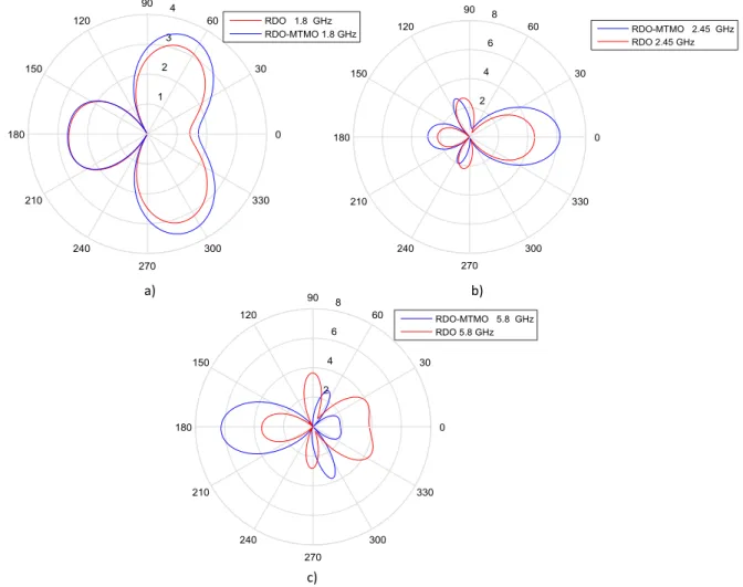
in Fig. 4, where the antenna gain is shown for central frequency of each bandwidth, and it can be seen
that the optimization brought and enhancement to the main and the secondary lobes, as desired in
harvesting application. The antenna performance improvement is summarized in Table I, which
shows the changes in the antenna dimensions,S11 parameter and input impedance Za values before and
after the optimization process. Lower S11 values were obtained and Za presented values closer to 50
(suitable for the antenna impedance matching).
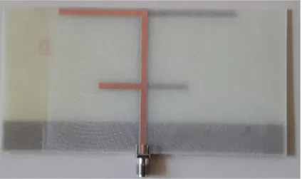
An antenna, with the optimized geometrical parameters, was printed on the same double-sided
copper FR4 substrate used in the optimization process, as illustrated in Fig. 5. The antenna S11
parameter was experimentally evaluated by using the network analyzer Keysight® E5071C and
obtained results are presented in Fig. 6. As can be observed a good concordance was found between
numerical and experimental results. The antenna prototype operates at DCS, PCS and WLAN
Brazilian Microwave and Optoelectronics Society-SBMO received 29 Sept 2018; for review 06 Nov 2018; accepted 19 Nov 2018
Fig. 3. S11 parameter: comparison between regular and optimized design.
TABLE I.ANTENNA GEOMETRICAL AND ELECTROMAGNETIC PARAMETERS
Antenna RD RDO
L1 (mm) 38 39.58 L2 (mm) 20 21.53 H1 (mm) 43 45.38 H2 (mm) 13 14.14 W (mm) 1.15 1.15
F (mm) 10 12.99 D (mm) 115 116.26 S11(f=1.80 GHz) -18.53 dB -23.61 dB
S11(f=2.45 GHz) -9.51 dB -15.58 dB
S11(f=5.8 GHz) -5.47 dB -6.09 dB
Za(f=1.80 GHz) (49.78+ j 8.67)Ω (44.57j4.96)Ω Za (f=2.45 GHz) (48.52 j 7.89)Ω (45.28 + j 5.91)Ω
Fig. 4. Antenna gain: comparison between RD and RDO results.
Fig. 5. F-shaped printed dipole antenna - RDO prototype.
a) b)
Brazilian Microwave and Optoelectronics Society-SBMO received 29 Sept 2018; for review 06 Nov 2018; accepted 19 Nov 2018
Fig. 6. S11 parameter: comparison between simulated and measured optimized design.
Although the results have improved after the optimization process, they did not attend the
requirement for operation in the HIPERLAN bandwidth. Thus, the inclusion of MTM unit cells in the
antenna structure was investigated in order to meet this request. So, four MTM sets, constituted by
four equal unit cells (like that illustrated Fig. 3), were printed over each antenna arm on its opposite
side, as illustrated in Fig. 7, with the purpose of broadening the antenna operation band at the
resonance peaks and also reduce the values of the S11 parameter.
The antenna geometry considered in the earlier optimization process has been kept and the MTM
unit cells were added. For the first analysis carried out, the unit cells, geometrical dimensions and
displacement dx, dy, da, dg and dc were adjusted arbitrarily considering the periodicity characteristic
of MTM [13].The dimensions used in this stage are presented in MTM column in Table II and result
obtained in Fig. 8. The Regular Design Optimized including not optimized MTM unit cell is called
Fig. 7. F-Shaped printed dipole antenna with SRR metamaterial unit cells.
Ground plane
dx
dy
da
SRR cells
Ground Plane
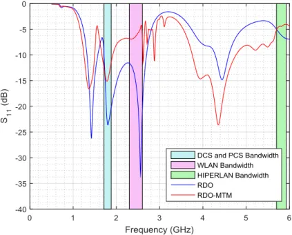
Fig. 8. S11 parameter: comparison between simulated results from RDO and RDO-MTM.
RDO-MTM. At first, the MTM unit cells were not able to enhance better values of S11 parameter at
the desired frequency due randomly cells placement [14]. The results obtained were worse than those
found for RDO geometry.
The GA algorithm was again employed, now to adjust the MTM unit cells geometry and
distributes them in the region in which boundaries are: the ground plane, the substrate limit and the
antenna structure. The GA was executed by using initial population of 120 individuals, a mutation rate
of 60% and 40 iterations at maximum. In this optimization process a greater computational resource
was employed, since a larger number of parameters were optimized. Some constraints were imposed
in the optimization process in order to avoid positioning one cell over the other and out of the
available area in the antenna structure. The results obtained in this stage are presented in Fig. 9. The
Regular Design Optimized including optimized MTM unit cell is called RDO-MTMO. As can be
observed the results obtained met the requirements established in this work at the three frequency
bands under consideration. The employment of optimized MTM cell brought an enhancement to the
antenna gain, as shown in Fig. 10, where a comparison between RDO and RDO-MTMO results is
made. It can also be seen, in Fig. 10 that the RDO-MTMO brought an enhancement to the antenna
gain especially at the HIPERLAN bandwidth. The antenna performance improvement also can be
observed in Table II, which shows the changes in the unit cells geometry and its periodic
displacement, the antenna S11 parameter and the input impedance Za values before and after the
optimization process. Lower S11 values were obtained and Za presented values closer to 50 for the
Brazilian Microwave and Optoelectronics Society-SBMO received 29 Sept 2018; for review 06 Nov 2018; accepted 19 Nov 2018
Fig. 9. S11 parameter: comparison between simulated results from RDO-MTM and RDO-MTMO.
TABLE II.MTM GEOMETRY AND S-PARAMETERS
Design Parameters RDOMTM RDOMTMO
Wm1 (mm) 1 1.13
Wm2 (mm) 1 1.13
Rm1 (mm) 2 1.61
Rm2 (mm) 4 3.59
G1 (mm) 1 1.13
G2 (mm) 1 1.13
DX (mm) 15 28.74
DY (mm) 12 10.91
Da (mm) 5 1.05
Dc (mm) 15 21.76
Dg (mm) 10 7.45
S11 (f=1.80 GHz) -23.61 dB -25.09 dB
S11 (f=2.45 GHz) -15.58 dB -35.53 dB
S11 (f=5.8 GHz) -6.09 dB -10.99 dB
Za(f=1.80 GHz) (46.83j9.06)Ω (47.12j6.83)Ω Za (f=2.45 GHz) (66.01j24.82)Ω (47.61 + j2.89)Ω
Fig. 10. Antenna gain comparison: between RDO and RDO-MTMO results.
The RDO-MTM design was printed on the same double-sided copper fiber glass substrate used in
the optimization process, as illustrated in Fig. 11. The antenna S11 parameter was experimentally
evaluated by using the network analyzer Keysight® E5071C and obtained results obtained are
presented in Fig. 12. As can be observed there was an accurate agreement between numerical and
experimental results. The antenna prototype can surely operate at DCS, PCS, WLAN and HIPERLAN
bandwidth.
a) b)
Brazilian Microwave and Optoelectronics Society-SBMO received 29 Sept 2018; for review 06 Nov 2018; accepted 19 Nov 2018
Fig. 12. S11 parameter: comparison between simulated and measured RDO-MTMO.
V. CONCLUSION
In this work a F-shaped printed dipole antenna with linear polarization was designed to operate
simultaneously at 1.8 GHz, 2.45 GHz and 5.8 GHz. In order to meet the proposed operating condition
a metamaterial surface, composed by SRR unit cell, was incorporated in the antenna structure. MTM
was understood as a periodic array of interspacing conducting elements that can behave as an
effective medium for electromagnetic scattering, when the wavelength is much longer than both the
element dimension and lattice spacing. The Genetic Algorithm technique proved to be adequate to
optimize the antenna and MTM dimensions. Numerical and experimental results obtained
demonstrated the designed metamaterial ability to improve the antenna performance, increasing their
bandwidth and gain and decreasing their return loss value. A multi-band antenna that operates at DCS,
PCS, WLAN and HIPERLAN bands were effectively achieved and it can be advantageously used in
the electromagnetic energy harvesting systems, since it can harvest energy from the four systems
simultaneously, what we consider a novelty.
ACKNOWLEDGMENT
This work was supported by the Brazilian Agencies: Conselho Nacional de Desenvolvimento
Científico e Tecnológico (CNPq), Fundação de Amparo à Pesquisa de MG (FAPEMIG), Coordenação
de Aperfeiçoamento de Pessoal de Nível Superior (CAPES), Centro Federal de Educação Tecnológica
de Minas Gerais (CEFET-MG).
REFERENCES
[1] J. Lal, H. K. Kan, W. S. T. Rowe, and K. L. Chung, “F-shaped shorted patch antenna with dual-frequency characteristics”, TENCON 2006 IEEE Region 10 Conference, Hong Kong, China, 2006.
[2] L.-W. Li, Y.-N. Li, T. S. Yeo, J. R. Mosig, and O. J. F. Martin, “A broadband and high-gain metamaterial microstrip
[3] A. Pirhadi, H. Bahrami, and J. Nasri,“Wideband high directive aperture coupled microstrip antenna design by using a FSS superstrate layer,” IEEE Transactions on Antennas and Propagation, vol. 60, no. 4, pp. 2101–2104, 2012.
[4] R.Pandeeswari, and S.Raghavan, “Microstrip antenna with complementary split ring resonator loaded ground plane for
gain enhancement,” Microwave and Optical Technology Letters, Wiley Publications, vol. 57, no. 2, February 2015.
[5] W.-J. Liao, S.-H. Chang, and L.-K. Li, “A compact planar multiband antenna for integrated mobile devices,”Progress In Electromagnetics Research, vol. 109, pp. 1–16, 2010.
[6] J.-Y. Jan, and L.-C. Tseng, “Small planar monopole antenna with a shorted parasiticinverted-L wire for wireless communications in the 2.4-,5.2-, and 5.8-GHz bands,”IEEE Transactions on Antennas and Propagation, vol. 52, no. 7, pp. 1903–1905,Jully 2004.
[7] S.-B. Chen, Y.-C. Jiao, W. Wang, and F.-S. Zhang, “Modified T-shaped planar monopole antennas for multiband operation,”IEEE Transactions on Microwave Theory And Techniques, vol. 54, no. 8, August 2006.
[8] IEEE Standard 802.11, “The IEEE 802.11 Standard”, U.S.A., 1997.
[9] IEEE Doc. IEEE P802.11-96/49C, “802.11 Tutorial – 802.11 MAC Entity: MAC Basic Access Mechanism Privacy and Access Control”, U.S.A., 1996.
[10] L. C. Godara, Handbook of Antennas in Wireless Communications, Boca Raton, CRC Press LTC, 2002.
[11] R. C. Johnson, Antenna Engineering Handbook, New York, McGraw-Hill, 1993.
[12] V. G. Veselago, “The electrodynamic of substances with simultaneously negative values of e and mu,” Soviet Physics Uspekhi, vol. 10, no. 4, pp. 509-514, 1968.
[13] D. R. Smith, W. J. Padilla, D. C. Vier, S. C. Nemat-Nasser, and S. Schultz, “Composite medium with simultaneously negative permeability and permittivity,”Physical Review Letters,vol. 84, no. 18, May 2000.
[14] J. B. Pendry, A. J. Holden, D. J. Robbins, and W. J. Stewart, “Magnetism from conductors and enhanced nonlinear phenomena,”IEEE Transactions on Microwave Theory and Techniques, vol. 47, no. 11, pp. 2075-2084, November 1999.
![Fig. 1. F-Shaped printed dipole antenna [1].](https://thumb-eu.123doks.com/thumbv2/123dok_br/16309639.718259/4.892.172.743.116.434/fig-f-shaped-printed-dipole-antenna.webp)