Abstract— The main objective of this work is the characterization of triangular array antenna with circular form by using the spectral domain technique. Firstly, the spectral domain formulation of single triangular patch antenna is given, in order to calculate its resonant frequencies and its radiation patterns. Then, we calculate and plot the total radiated field which is the multiplication of a single element radiation by the array factor, when patches are made in a circular arrangement. Comparing to the exiting array antenna design, the numerical results, obtained from the implementation of our calculations, have shown that the networking increases the gain, improves the directivity and controls the bandwidth with a compact form of the antenna arrangement. In addition the effects of different parameters of the structure on its performances are presented.
Index Terms— Triangular patch antenna, compact circular array, spectral domain method, radiation pattern.
I. INTRODUCTION
Micro-strip patch antennas were first proposed in the early 1970s, since then a plethora of activity
in this antenna engineering area has occurred, probably more than in any other field of antenna
research and development. Micro-strip patch antennas have several well-known advantages over other
antenna structures, including their low profile and hence conformal nature, light weight, low cost of
production, robust nature, and compatibility with microwave monolithic integrated circuits (MMICs)
and optoelectronic integrated circuits (OEICs) technologies [1]. Because of these merits, forms of the
micro-strip patch antenna have been utilized in many applications such as in mobile communication
base stations, space satellite communication systems, and even mobile communication handset
terminals. Unfortunately, despite the previously mentioned features, micro-strip patch antennas suffer
from several inherent disadvantages of this technology in its pure form, namely, they have narrow
bandwidth and relatively poor radiation efficiency resulting from surface wave excitation, ohmic
dissipation and dielectric losses.
The triangular microstrip patch is one of the most common shapes, having a wide range of
applications in the circuit elements for the modern wireless antennas. There are several investigations
Rigorous Analysis of a Compact Triangular
Antenna Array Using the Spectral Domain
Method
C. Aissaoui, A. Benghalia,
Laboratoire de Recherche desHyperfréquences et Semiconducteurs, Département d’électronique, Université des Frères Mentouri, Constantine, Algérie.
[email protected], [email protected]
I. Messaoudene
realized by the antenna engineers and researchers to create new and effective triangular microstrip
patch designs, with compact size and high-directivity based on the Sierpinski fractal presented in [2]
and a dual-frequency antenna based on the Sierpinski fractal with two parasitic patches to enhance the
impedance bandwidth, reported by [3].The use of a single patch antenna is often insufficient to meet
the imposed radiation constraints. Specific characteristics, such as a high gain, a conformal lobe can
usually be obtained by grouping multiple radiating elements to form an antenna array. The printed
array antennas are constituted by radiating elements connected to each other by sections of micro-strip
line. The antenna elements operate at the same frequency and are disposed periodically in one or more
directions. The array antennas are currently used in many applications; space telecommunications
radar systems and radio control of missiles; and can have different shapes: linear arrays or planar
arrays (two-dimensional) [4].
Many investigations are reported to use the triangular patches as an array antenna [5-6]. In these
designs, the radiated elements are generally arranged in the linear or rectangular forms. However, this
antenna configuration array presents the disadvantage that the size of the structure is very large. In
[7], an undersampled high directivity microstrip patch array with a reduced number of radiating
elements inspired on the Sierpinski fractal is presented.Inthis paper, we present a compact triangular
antenna array with circular arrangement. The proposed structure is analyzed using a rigorous method
in spectral domain.
II. SOLUTION OF SINGLE TRIANGULAR PATCH ANTENNA IN SPECTRAL DOMAIN
Fig. 1 represents the single triangular patch antenna under consideration.
Fig. 1. Equilateral triangular patch
A. Mathematical Formulation
The wave equation in the dielectric area of the microstrip antenna with free source is
two-dimensional and defined by the following equation:
0 2 2 2
2 2
2 2
i i i i
i k U
z U y
U x
U
(1)
z
x
where ki
i
i2
The index i=1,2 indicates the two dielectric mediums (the substrate and the air )
Using the Fourier transform, the equation (1) can be written as follows, when the radiation is along
the (oy) axis [8]:
0 ~ ~ 2 2 2
i i
i U
dy U d
(2)
The formulation of the equation (2) in the spectral domain leads to the following matrix form:
x z z xE
E
J
J
G
G
G
G
~
~
~
~
)
,
,
(
)
,
,
(
)
,
,
(
)
,
,
(
22 21 12 11
(3)where G11(,,),…, G22(,,) are the Green functions of the problem, and equation (3) is the
final equation of the problem. By applying of the Galerkin technique, this equation is converted into a
system of linear and homogeneous equations, such as [5]:
Q q b C a C P p Q q q q q p p
q ( ) ( 0 ' 1,...,
1 1 2 , 1 ,' 1 , 1 ,'
(4.a) P p b C a C P p Q q q q p p pp ( ) ( 0 ' 1,...,
1 1 2 , 2 ,' 1 , 2 ,'
(4.b)The coefficients are formulated as follows [5]:
G J J d d
Cq p
zq xp ( , , )~ ( , )~ ( , ) )
( 11 , ' ,
1 , 1 ,' (5.a)
G J J d d
Cqq
zq zq ( , , )~ ( , ) ~ ( , ) )
( 12 , ' ,
2 , 1 ,' (5.b)
G J J d d
Cp p
xp xp ( , , )~ ( , )~ ( , ) )
( 21 , ' ,
1 , 2 ,' (5.c)
G J J d d
Cp p
xp zq ( , , )~ ( , )~ ( , ) )
( 22 , ' ,
2 , 2
,' (5.d)
The compact form of the system (4) is
] 0 [ )] ( [( b a
C (6)
The resulting system of equation (6) is homogeneous; the significant solutions are obtained when
0 )] (
det[(C (7)
equations (5), we can observe that the coefficients are complex, because in these equations parameters α and β span the whole spectrum of modes (evanescent and propagating). So, the resonant frequencies computed should be complex too.
i
r
j
(8)The real part is the actual resonant frequency and the imaginary part represents the losses by
radiation.
Once the resonance frequency is determined, we can calculate the radiated field by the patch from
equations (3), as follow
2 2
z
x E
E
EF (9)
B. Basis Functions Choice
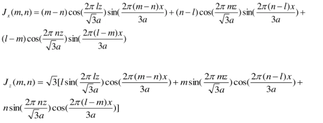
In this work we have opted for the basis functions of equilateral patch proposed by W.Chen, K. F.
Lee and J. S. Dahele in [9] :
) 3 ) ( 2 sin( ) 3 2 cos( ) ( ) 3 ) ( 2 sin( ) 3 2 cos( ) ( ) 3 ) ( 2 sin( ) 3 2 cos( ) ( ) , ( a x m l a nz m l a x l n a mz l n a x n m a lz n m n m Jx (10.a) )] 3 ) ( 2 cos( ) 3 2 sin( ) 3 ) ( 2 cos( ) 3 2 sin( ) 3 ) ( 2 cos( ) 3 2 sin( [ 3 ) , ( a x m l a nz n a x l n a mz m a x n m a lz l n m Jz (10.b)
'a' is the length side of the equilateral patch.
l, m, n are integers designate the different modes, such as: l+m+n=0.
III. THE ANTENNA ARRAY ARRANGEMENT
Fig. 2. Circular arrangement of N triangular patches
The Figure 2 illustrates the arrangement of the triangular patch antennas to form the proposed
antenna array structure.
The far field of any antenna array with identical radiating elements is the product of the element x
z
y
factor (EF) and the array factor (AF): (EF) × (AF). The AF depends on the geometric arrangement of
the array elements, the spacing of the elements, and the electrical phase of each element [10]. This
factor is given by:
N
n k
j n n
e AF
1
) cos( sin
(11)
Where
) cos(
sin 0 0 n
n k
(12.a)
) 1 (
2
n
N
n
(12.b)
where α is the array radius and
nis the angular location of each element. The center of thetriangular patch is situated at a distance equal to the radius of the circular array with the phase angle
n
, each element has an associated phase
n.IV. NUMERICAL RESULTS AND DISCUSSIONS
The above mathematical model is implemented in FORTRAN program, and the obtained results are
presented in terms of resonant frequencies and the radiations patterns for the single triangular patch.
Then, the total radiation patterns of the circular array antenna is calculated in MATLAB.
A. Single Patch Antenna
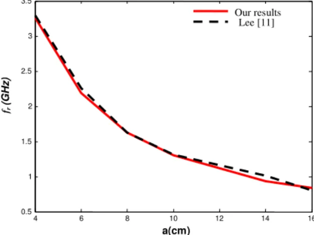
Figure 3 shows the resonant frequency variation of an equilateral patch triangle. From this figure, it
is clear that when the dimensions of the patch increase the resonant frequency decreases and the
results of our computation are very close to those obtained by [11].
Fig. 3. Resonant frequency variation with the lateral length of the equilateral triangle; d=0.159cm, εr=2.32.
4 6 8 10 12 14 16
0.5 1 1.5 2 2.5 3 3.5
a(cm)
fr
(G
H
z)
TABLE I. THE RESONANT FREQUENCY OF EQUILATERAL PATCH ANTENNA FOR DIFFERENT MODES,εr=10.5,a=4.1cm,d=0.7mm
Mode frmes GHz [9]
frmes GHz
Our results
frmom/ frmes
[9]
fr/ frmes
[10]
fr/ frmes
Our results
TM10 1.519 1.542 1.002 0.991 1.015
TM20 2.995 3.045 1.010 1.006 1.016
TM21 3.973 3.977 1.016 1.003 1.001
From Table I, we note that by going from one mode to the higher one, the resonance frequency
values increase. In addition, our calculations give resonant frequencies close to the measured and
calculated results reported in the literature [12-13].
TABLE II. COMPARISON OF RESONANT FREQUENCIES (OUR RESULTS WITH ANGUERA RESULTS) Antenna Square Equilateral patch Bow Tie SPK Bow Tie 3 [2] [our result] [2] [2] Area reduction [A/Asquare] 1 0.45 0.40 0.33 Resonant freq. [GHz] 1.947 1.542 1.247 1.128
In Table II, the area of square patch is (40mm x 40mm) and the length side of the equilateral patch
is a=41mm. It is clear that when the area reduction of different shapes decreases the resonant
frequency decreases.
(a)
(c)
Fig. 4. Radiation patterns of an equilateral patch antenna for; (a) TM10 mode, (b) TM20 mode, (a) TM21 mode.
a=1cm, h=0.159cm and εr=2.32.
Figure 4 shows the calculated radiation patterns of an equilateral patch antenna for different
modes. According to the three radiation patterns obtained, it can be noted that from one mode to a
higher one, the radiated field shape changes and become broader and less directive than the
fundamental mode (TM10) of the antenna. In other words, the operating frequency of the antenna
affects the radiated field.
B. The Circular Form for the Triangular Array Antennas
In the following, the dimensions of equilateral patch antennas are: a=1cm, h=0.159cm and εr=2.32.
The effect of number of patches N
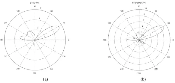
Fig. 5 shows the calculated radiation patterns of acircular array with N equilateral patches. It
is observed that the total radiated field is more directional than the single patch and its amplitude
increases with the number of patches and the side lobes decrease.
(a) (b)
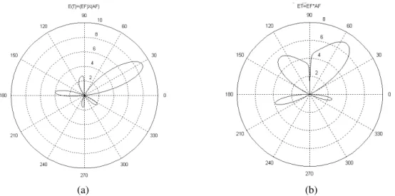
From Fig. 6, it can be seen that the main lobe direction is controlled by the array factor θ0.
However, the side lobes become larger and the intensity of the main lobe diminishes when the steering angle θ0 increases.
(a) (b)
Fig. 6. Radiated field by a circular array with equilateral patches; α/λ=1, N=10, φ=0° for; (a) θ0=30°, (b) θ0=60°. The effect of spacing between elements d
In this case, we note that when the distance between elements decreases the main lobe becomes
more important and the side lobes decrease, as illustrated in Fig. 7.
(a) (b)
Fig. 7. Radiated field by a circular array with equilateral patches; θ0=30°, φ=0°, N=6, for; (a) α/λ=1, (b) α/λ=0.5. V. CONCLUSION
In this work, a numerical solution of the integral equation of the electric field is presented, and the
equilateral basis functions are used for the Galerkin approach. To validate our calculations, we have
confronted our results with theoretical and experimental data from the literature. For the case of a
single patch we have illustrated the effect of different parameters of the antenna on the resonance
frequency. The radiated field is calculated and plotted for different modes. For the case of circular
(N), the distance between the elements (d) and the steering angle (θ0) on the total radiated field are studied.
REFERENCES
[1] R. Waterhouse, “Handbook of Antennas Communications - Part B - Chapter 6” Edited by Lal Chand Godara CRC Press Boca Raton London New York Washington, D.C. LLC, 2002.
[2] Jaume Anguera, Carles Puente, Carmen Borja, Raquel Montero, and Jordi Soler, “Small and high-directivity bow-tie patch antenna based on the Sierpinski fractal”, Microwave And Optical Technology Letters, Vol. 31, No. 3, pp. 239-241, November 2001.
[3] Jaume Anguera, Enrique Martínez, Carles Puente,Carmen Borja, and Jordi Soler, “Broad-band dual-frequency microstrip patch antenna with modified Sierpinski fractal geometry”, IEEE Transactions on Antennas And Propagation, Vol. 52, No. 1, January 2004.
[4] B. Pattan, “Robust Modulation Methods and Smart Antennas in Wireless Communications”, Prentice Hall, New York, 2000.
[5] F. Yuli Zulkifli, S. Tri Lomorti, and E. T. Rahardjo, “Improved Design of Triangular Patch Linear Array Microstrip Antenna Using Isosceles-Triangular Defected Ground Structure” Proceedings of Asia-Pacific Microwave Conference, 2007.
[6] D. Kumar and P. K. S. Pourush, “Beam Scanning Characteristics of Microstrip Triangular Array Antenna on Normally Biased Nial Ferrite”, Proceedings of Direct and Inverse Problems Electromagnetic and Acoustic Wave Theory (DIPED), 2004.
[7] Jaume Anguera, Gemma Montesinos, Carles Puente, Carmen Borja, and Jordi Soler, « An Undersampled high directivity microstrip patch array with a reduced number of radiating elements inspired on the Sierpinski fractal”, Microwave and optical technology letters, Vol. 37, No. 2, April 20 2003.
[8] D. Mirshekar-Syanhkal, “Spectral domain method for microwave integrated circuit”, Research Studies Press Ltd. John Wiley & Sons Inc. (New York), 1990.
[9] Wei Chen, Kai Fong Lee, and S. Dahele, "Theoretical and experimental studies of the resonant frequencies of the equilateral triangular microstrip antenna”, IEEE Trans on Antennas and propag,
vol. 40, no. 10, pp 1253-1256, oct 1992.
[10]Frank B. Gross, “Smart Antennas for wireless communications”, Mc Graw-Hill 2005.
[11]Azziz Nachit and Jouad Foshi, “Spectral domain integral equation approach of an equilateral triangular microstrip antenna using the moment method”, Journal of microwaves and optoelectronics. vol. 2, no. 1, Juin 2000.
[12]Wei Chen, Kai Fong Lee, and S. Dahele, “Theoretical and experimental studies of the resonnant frequencies of the equilateral triangular microstrip antenna”, IEEE Trans on Antennas and propag, vol. 40, no. 10, PP 1253-1256, Oct 1992.