Advances in Mechanical Engineering 2016, Vol. 8(1) 1–9
ÓThe Author(s) 2016 DOI: 10.1177/1687814016629347 aime.sagepub.com
Study on creep damage and life
prediction of threaded connections at
high temperature
Qingmin Yu and Honglei Zhou
Abstract
In this study, Kachanov–Rabotnov model and stress relaxation damage constitutive equations deduced from Kachanov– Rabotnov model were applied to analyze the creep damage and to predict life for threaded connection structure at high temperature with finite element method. The parameters of Kachanov–Rabotnov model were obtained by fitting the results of creep experiments for titanium alloy at 650°C. Based on the experimental and finite element analysis results for standard specimen, a creep failure criterion was established. Then the influences of the external tensile load on the creep damage and life, as well as the stress relaxation on the initial preload, were studied. The analysis of stress relaxa-tion for bolt shows that the stress relaxarelaxa-tion has a remarkable effect on the bolt preload. The preloads decrease to a determined value with creep time and remain almost unchanged later. When the determined value is less than the required preload acting on the bolt, the structure will fail due to insufficient preload caused by stress relaxation.
Keywords
Creep damage, creep life, finite element analysis, stress relaxation, preload
Date received: 18 July 2015; accepted: 26 December 2015
Academic Editor: Shan-Tung Tu
Introduction
Bolted connection is an important fastening member widely used in gas turbine, steam pipes, boilers, and other high temperature systems. The bolt is used to ensure the integrity of threaded connections and to make the structure work safely and reliably. The fas-tening function of bolt will be weakened by creep and stress relaxation at high temperature. Creep and stress relaxation are two similar, yet distinct, mechanisms by which the amount of plastic strain increases with time at high temperature. Creep is a phenomenon of plastic strain accumulating due to constant stress. It is a result of long-term exposure to high levels of stress that are still below the yield strength of the material and is more severe in materials subjected to heat for long time, and it generally becomes more significant as the tempera-ture is approaching the melting point. However, stress
relaxation means that stress decreases with creep time, while strain remains unchanged. When the bolted struc-tures work at high temperature, the influence of stress relaxation on the preload should be considered. But there is little public literature related to this issue.
Many researchers have studied the creep and creep damage of bolt materials. AA Mir and S Murphy1 investigated the load relaxation process in zinc alloys at higher temperatures and compared the load relaxation
School of Mechanics, Civil Engineering and Architecture, Northwestern Polytechnical University, Xi’an, P.R. China
Corresponding author:
Qingmin Yu, School of Mechanics, Civil Engineering and Architecture, Northwestern Polytechnical University, Chang’an Campus, P.O. Box 883, No. 1 Dongxiang Road, Xi’an 710129, P.R. China.
Email: [email protected]
behavior under similar testing conditions. The effect of temperature on creep of bolt material and retention of bolt load was discussed. Xu et al.2carried out the creep rupture experiments of Nimonic 80A uniaxial specimen and hollow bolts at 550°C under different stress. They
improved the creep damage model by inducting strain threshold value based on Norton–Bailey–Kachanov creep model and modeled the creep behaviors of hollow bolt using ABAQUS subroutine. Chang and Wang3 used a classical constitutive model to simulate the stress- and temperature-dependent creep behavior of a die casting A380-T5 aluminum alloy and analyzed the bolt load retention behavior of the material in a head bolt joint in an aluminum engine under the condition of thermal cycle by finite element method. Guo et al.4,5 constructed a relaxation damage model based on Schlottner–Seele average creep rupture rate theory and relaxation function and used it to predict the relaxation damage life of high temperature bolting material 1Cr10NiMoW2VNbN. Results obtained from the developed model were validated by relaxation tests. They also built a new stress relaxation constitutive model by introducing continuum damage mechanics into the stress relaxation to analyze the stress relaxation damage mechanism and its relationship with the creep damage. The stress relaxation performance and relaxa-tion damage of the bolting material of 1Cr10NiMoW2VNbN steel were predicted. Jin6 estab-lished a dynamic formulation based on the basic char-acteristics of metal stress relaxation at high temperature to predict the stress relaxation perfor-mance of bolt steel 20Cr1Mo1VTiB used in turbine under various initial conditions. The validity and preci-sion of the proposed formulation were justified by the relaxation experimental data of several bolt steels, and the changes between relaxation strain rate and time as well as its trend were investigated. Analysis results pro-vide a theoretical basis for the prediction of stress relaxation of material in engineering practice. Mao et al.7 conducted the creep damage calculation for a turbine casting under the action of bolt relaxation by finite element method, so as to analyze and compare the variation of stress, strain, and the creep damage with time. The effect of bolt relaxation on the creep strength of turbine casting was discussed.
The previous study was mostly focused on the anal-ysis of creep damage for bolt materials, while little attention was given to creep damage and stress relaxa-tion of threaded connecrelaxa-tion structures at high tem-perature. Since Kachanov–Rabotnov (K-R) model8,9 describes the evolution of creep damage with creep time, it has been widely used to study the creep dam-age behavior for different materials, loading condi-tions, and specimen types.10–13 In this study, K-R model was adopted to analyze the creep damage evo-lution and life prediction for threaded connection
structure at high temperature. The stress relaxation damage constitutive equations were deduced from K-R model. Then the creep strain and damage of uniax-ial standard specimen obtained by finite element method (FEM) were compared with the experimental results and a creep failure criterion was established. The influences of the tensile load on the creep damage and the stress relaxation on the initial preload are discussed.
Constitutive equations and finite
element model
Creep damage constitutive equations
Creep plays a key role in the damage and life of threaded connection structure at high temperature. In order to guarantee the normal operation of the threaded structure at high temperatures, it is necessary to study the creep and damage behavior. In this study, the creep damage and life prediction of bolt under con-stant axial tensile load at high temperature were ana-lyzed using FEM.
The creep of metals occurs at high temperature under the action of continuous load. Creep damage is an irreversible occurrence during the process of creep deformation, which is mainly caused by the accumula-tion of dislocaaccumula-tions between lattices within materials, and produces micro-cracks and micro-holes between grain boundaries and lattices. In this study, we used K-R model considering the coupling of creep and dam-age to calculate the creep strain and damdam-age of bolt under different tensile loads. The expression of K-R model is shown in equation (1)10
_ ec=B
se ð Þn
1v
ð Þn
_
v=D
as1+ð1aÞse
½ X
1v
ð ÞF
ð1Þ
wheree_cis equivalent creep strain rate,seis Von Mises
equivalent stress, s1 is maximum principal stress, and
vis the damage variable which ranges fromv=0(no
damage) tov=1(failure).B,D,n,X,F, andaare all
material parameters. The parameter a describes the
relative importance of s1 and se on creep rupture,
which ranges from a=0 (equivalent stress dominant)
to a=1 (maximum principal stress dominant). The
values of model parameters will be discussed in section ‘‘Results and discussions.’’
Stress relaxation damage constitutive equations
The creep stress over bolt, especially that at the root of thread, gradually decreases with time because of stress relaxation. In this case, the creep stress in the threaded connection structure is dominated by a decreasing func-tion of time. The rate of creep damage will decrease with the decrease of stress. Here, we got the following equation (2) by replacingsein equation (1) withse(t)
_ ec=B
seð Þt
1v
n
_
v=D seð Þt
½ X
1v
ð ÞF
ð2Þ
Total strain remains constant at any time for stress relaxation; therefore, we have the expressions of equa-tions (3) and (4)
ee+ep+ec=const ð3Þ
ee=
seð Þt
E ð4Þ
whereee is elastic strain, ep is equivalent plastic strain, ecis equivalent creep strain,se(t) is transient Von Mises
stress at the time oft, andEis Young’s modulus. Performing derivation on both sides of equation (3) ande_p=0, we can obtain equation (5)
_
ee+e_c=0 ð5Þ
Substituting equations (2) and (4) into equation (5), we can establish the following expression of equation (6)
_
seð Þt
E +B
seð Þt
½ n
1v
ð Þn =0 ð6Þ
Integrating the first expression of equation (2) over time from 0 tot, we have equation shown below
1v
ð Þn= 1Dseð Þt XtðF+1Þ
h iF+n1
ð7Þ
Finally, equation (8) of the stress relaxation rate equation is obtained by substituting equation (7) into equation (6)
_
seð Þt = EB
seð Þt
½ n
1Dseð Þt XtðF+1Þ
h iF+n1
ð8Þ
Finite element model
The three-dimensional finite element model of threaded connection structure consists of an M1231.75 bolt, nut, and joints. Helix angle of threaded portion was ignored in bolt part. Since the whole structure is
symmetrical, only 1/4 structure model was established in order to save computing time, as shown in Figure 1(a).
Finite element models of bolt, nut, and joint were meshed using 8-node linear brick, reduced integration with hourglass control elements (C3D8R). In order to improve the accuracy of calculation, external threads of bolt and internal threads of nut were meshed with finer elements especially in the portion of thread root, whereas other regions and joint were meshed with coarse elements as shown in Figure 1(b). There were 75,040 elements and 66,384 nodes in the whole finite element model.
Pressure load was applied on the contact surface of nut and joint to apply axial tensile load during the pro-cess of finite element analysis. All freedoms of the bot-tom surface of the bolt head were fixed, and symmetric boundary condition was applied to all symmetrical sur-faces of upper and lower joints as shown in Figure 1(a).
Results and discussions
Creep damage in uniaxial specimen model
The creep damage and life prediction of bolt under ten-sile load at high temperature were analyzed using FEM by ABAQUS with the user subroutine CREEP14in this study. In order to verify the user subroutine, uniaxial specimen model was established and the calculation for creep strain and damage under uniaxial tensile load was completed. Results obtained by FEM based on K-R model were compared with experimental results of titanium alloy from Hyde et al.,15as shown in Figure 2. Uniaxial creep test for titanium alloy was conducted at 650°C under different stress, and the
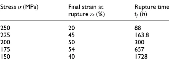
results are listed in Table 1.15The elastic modulus and Poisson ratio of titanium alloy at 650°C are 89.5 GPa
and 0.3, respectively, and the yield strength is 450 MPa, and the creep parameters in equation (1), derived from experimental results listed in Table 1, were shown in Table 2.15 On the other hand, we takea=0based on
the comparison between creep experimental and FEM
results of Hyde et al.15 The elastic modulus and Poisson ratio of joint material (superalloy) at tempera-ture of 650°C are 204 GPa and 0.3, respectively.
As can be seen from Figure 2, the agreement between the creep damage model of equation (1) and the experi-mental data is generally good for all stress levels, which has validated the creep damage model and FEM calcu-lation. The corresponding creep damage accumulation results of uniaxial specimen under different stress pre-dicted by FEM are shown in Figure 3.
It can be seen from Figure 3 that creep rupture is predicted to occur when the creep damage is in the range of 0.5–1. On the other hand, the damage rate begins to sharply accelerate after creep damage reaches 0.5. Due to this rapid acceleration of creep damage, the time taken for further damage accumulation from 0.5 to 1 is reasonably small, compared with the whole creep time. In view of this reason, we choose the damage value of v=1 as the failure criterion to predict creep
rupture and life of material, and then to predict the creep damage and life of bolt. The creep life of uniaxial specimens at each stress level predicted by finite ele-ment analysis was compared with the experiele-mental results, which is shown in Table 3. Comparative results show that the creep life predicted is slightly lower than the actual life and the maximal relative error of predic-tion value is 11.7% and the minimal one is 1.5%.
Creep damage and creep life of bolt under external
loads
Creep damage and life prediction of bolt for threaded connections under different axial tensile load were ana-lyzed by FEM. Bolt is usually tightened to the situation that preload achieved reaches to around 70% of the specified proof load of the bolt in engineering. The proof loadFpcould be calculated by equation (9)
Fp=Absy ð9Þ
whereAb is cross-sectional area of bolt shank andsyis
yield strength of bolt material.
In this article, five different loads were chosen to analyze the creep damage and predict the life of bolt
Figure 2. Comparison of creep strain for uniaxial creep experiments and finite element analysis.
Table 1. Uniaxial creep test results at 650°C under different
constant tensile load.
Stresss(MPa) Final strain at
ruptureef(%)
Rupture time
tf(h)
250 20 88
225 45 163.8
200 50 300
175 54 657
150 40 1728
Table 2. Creep damage parameters of titanium alloy at 650°C.
B D n X F
5.623310218 1.921310216 5.911 5.416 4.8
Table 3. Comparison of creep life between predictive and experimental results for uniaxial specimens at each stress level.
Stress level
250 MPa 225 MPa 200 MPa 175 MPa 150 MPa
Predicted life
86.7 h 150.7 h 280 h 580 h 1570 h
Test life 88 h 163.8 h 300 h 657 h 1728 h Relative
error
1.5% 8.0% 6.7% 11.7% 9.1%
for threaded connections. The value of different tensile loads is F=0
:7Fp=8:9kN, F=0:6Fp=7:6kN,
F=0
:5Fp=6:4kN, F=0:4Fp=5:1kN, and
F=0
:3Fp=3:8kN, respectively. Elastic–plastic
prop-erties of titanium alloy at 650°C are assigned to the bolt
and nut, while joint material (superalloy) is assumed to be linear in the finite element model.
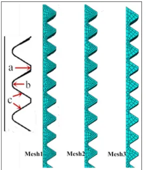
The mesh dependence should be considered as there is stress concentration in the model, especially in threaded portion for creep damage calculation. In order to check the sensitivity of model, the threaded portion, shown in Figure 4, was meshed with three dif-ferent generation methods (named with Mesh1, Mesh2, and Mesh3, respectively) and the corresponding ele-ment size, and eleele-ment and node numbers for each method are listed in Table 4. Mesh1 contains 29,791 elements which are approximately 1.6 times that of Mesh2 and 3.8 times that of Mesh3. The evolution of equivalent creep strain and creep damage with time obtained from every model with different element num-bers are shown in Figures 5 and 6. The results of Mesh1 are almost identical with that of Mesh2. There
is a little difference between results of Mesh3 and those of Mesh1 and Mesh2, which indicates that the accuracy of calculation results cannot be improved significantly by increasing the element number. Meanwhile, the maximum creep damage appears at the same location, that is, the root of the first engaged thread. This means that the element number has a small effect on the calcu-lation results of creep strain and damage. Therefore,
Figure 4. Region meshes with different numbers of elements of threaded portion.
Table 4. Element size, number of nodes, and elements of different region meshes.
No. Element size Number of nodes Number of elements
a b c
Mesh1 0.3 0.04 0.11 35,776 29,791
Mesh2 0.45 0.051 0.16 22,912 18,476
Mesh3 0.8 0.1 0.34 10,272 7874
Figure 5. Comparative curves of the effect of the number of elements on creep strain of bolt with creep time.
the latter calculations were performed with model meshed by the method Mesh1.
Von Mises stress distributions over threaded connec-tions when axial tensile load F is 3800, 5100, 6400, 7600, and 8900 N, respectively, were obtained from finite element calculation. The results show that the maximum stress is located at the root of the first engaged thread of bolt because of stress concentration, as Figure 7 shows stress contours of threaded connec-tion structure when axial tensile load is 6.4 kN. The corresponding maximum equivalent stress for each axial tensile load is 486.8, 517.0, 533.9, 532.0, and 530.7 MPa, respectively. Plastic deformation occurs at the root of thread after the external tensile load was applied. The corresponding maximum equivalent plas-tic strain for each axial tensile load is 0.4197%, 1.231%, 2.065%, 3.027%, and 4.538%. Figure 8 shows the stress contours of joint when axial tensile load is 6.4 kN. The maximum equivalent stress is 94.93 MPa, which is far smaller than the value of maximum stress of 486.3 MPa. Therefore, creep properties of joint were neglected in the process of finite element analysis.
Creep strain and damage distributions over bolt were also obtained and the results show that both maximum creep strain and damage are located at the root of the first engaged thread of bolt, which is similar to stress distributions. Equivalent creep strain and damage con-tours of bolt when axial tensile load is 6.4 kN, creep time is 28.30 h, are presented in Figure 9. The maximum creep damage of bolt is 0.9974 when creep time reaches 28.30 h, which can be seen from Figure 9, and creep rupture is thought to occur at this time.
Figures 10 and 11 show the maximum equivalent creep strain and damage accumulation at the root of the first engaged thread predicted by FEM plotted against time under different axial tensile loads.
As can be seen from Figures 10 and 11, creep strain and damage increase with creep time during the process of creep at high temperature. Axial tensile load has
Figure 7. Stress contours of threaded connection structure whenF=6:4 kN.
Figure 8. Stress contours of joint whenF=6:4 kN.
Figure 9. Creep strain and damage contours of bolt when
F=3 kN,t=28:3 h.
great influence on creep strain and damage. Creep strain and damage at high stress is generally greater than that at lower stress levels in the same period of time. The corresponding creep life of bolt is 4.8, 11.1, 28.3, 97.2, and 480.2 h according to the failure criterion ofv=1, when axial tensile loadFis 8900, 7600, 6400,
5100, and 3800 N, respectively, as shown in Figure 11. This means that the creep life of bolt decreases drama-tically when the external tensile load increases from 3800 to 8900 N.
Influence of stress relaxation on preload
Stress relaxation damage constitutive equation was deduced based on K-R model in this work. Stress relaxation behavior of bolt under the action of preload and the effect of stress relaxation on preload retention for threaded connections was discussed.
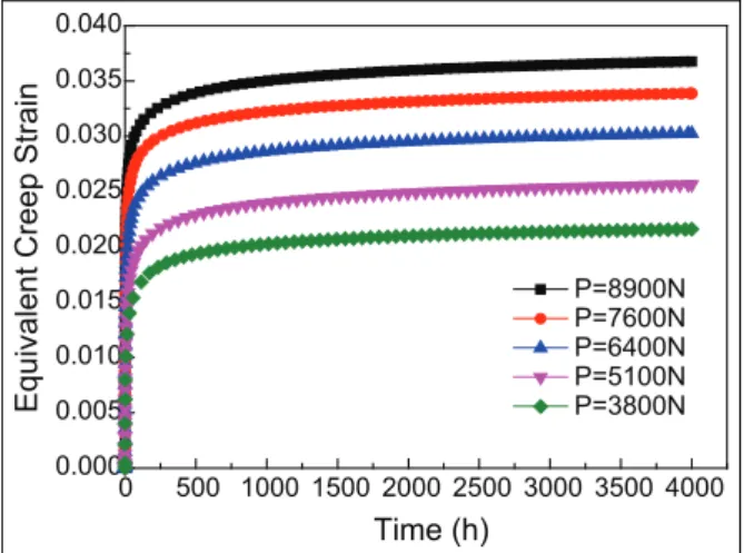
Creep and stress relaxation affects each other when the threaded connection structure works at high tem-perature. The maximum equivalent creep strain and damage accumulation with time when initial preloadP
is 8900, 7600, 6400, 5100, and 3800 N, respectively, were obtained through the analysis of stress relaxation for threaded connection structure as shown in Figures 12 and 13. It can be seen from Figure 12 that the maxi-mum equivalent creep strain grows quickly at the initial stage of creep and the growth rate declines rapidly with the increase of creep time; the rate approaches 0 when the creep time is long enough. The figure also shows that the value of maximum equivalent creep strain increases with the initial preload increasing.
It also can be seen from Figure 13 that the creep damage rate is larger at the initial stage of creep and then starts to decrease gradually with time increasing until close to 0 and remains almost unchanged later. Therefore, the damage increases sharply to a corre-sponding value in a short time and then increases slowly with time until damage remains almost a constant.
The two figures show that the larger the initial pre-load, the greater the creep strain and damage. The maximal equivalent creep strain is only 0.037 and the damage is only 0.084 when initial preloadPis 8900 N, creep time reaches to 4000 h. The creep damage value ofv=0:084, is much smaller than the failure criterion
ofv=1as mentioned in section ‘‘creep damage in
uni-axial specimen model,’’ which means that bolt will not fracture when threaded connections structure are only under the action of initial preload because of the influ-ence of stress relaxation. The results show that the ini-tial preload has a great effect on the creep strain and damage.
Figure 14 shows the evolution of the maximum stress with creep time under different initial preloads in bolt. The stress relaxation curves were obtained by FEM and equation (8), respectively.
Figure 11. Evolution of maximum creep damage with creep time for different axial tensile loads.
Figure 12. Maximum equivalent creep strain accumulation with time under different initial preloads.
As can be seen from Figure 14, the stress relaxation curves are consistent for different initial preloads when only preload acts on the threaded structure. Stress relaxation rate is large in the initial stage and the stress declines sharply to a very small value in a very short period of time. Then, the stress relaxation rate begins to decelerate until close to 0 and remains almost unchanged later. On the other hand, the stress decreases little with time increasing until it is close to a certain value (stress relaxation limit) in this process and remains almost unchanged later, similar to stress relaxation rate.
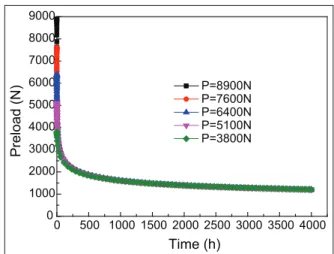
The influence of stress relaxation on bolt preload with increase of creep time for different initial preloads is shown in Figure 15. As can be seen from Figure 15, stress relaxation has a great impact on bolt preload. The decreasing rate of preload with creep time is larger at the initial stage of creep and reduces gradually with creep time until close to a determined value and remains almost unchanged later. If the determined value is less than the necessary preload in bolt, the structure will not work safely and reliably. For example, the preload decreases to 1198 N when initial preload is 8900 N and creep time reaches to 4000 h, which will lead to the fail-ure of threaded connections in practice due to insuffi-cient preload. On the other hand, the initial preload has no influence on the preload during the process of creep except the beginning stage of creep. That is to say, the preloads are different at the beginning of creep accord-ing to the different initial preloads and become close with the development of creep. The curves of bolt pre-load under different initial prepre-loads are almost consis-tent when creep time is beyond 500 h.
Conclusion
In this study, K-R model was applied to analyze the creep damage, stress relaxation, and life prediction for
threaded connection structure at high temperature. The parameters of K-R model for titanium alloy were derived from the creep experiments at 650°C performed
by Hyde et al.15 and used to analyze the evolution of creep strain and damage in the threaded connection structure with FEM. The influences of the external ten-sile load on the creep damage and the stress relaxation on the initial preload, respectively, were discussed. Based on the results of finite element analysis, the fol-lowing conclusions can be drawn:
1. The creep strain and damage results calculated by FEM with uniaxial specimen agree well with uniaxial creep test results. This validates the derived parameters for K-R model.
2. The influence of external tensile load on the creep damage and life has been analyzed for bolted structure at high temperature. The results show that both maximum creep strain and dam-age are located at the root of the first engdam-aged thread of bolt. The axial tensile load has great influence on the creep strain and damage as well as creep life. The creep strain and damage increase with creep time during creep and the creep life decreases dramatically when the exter-nal axial tensile load increases from 3800 to 8900 N.
3. The effect of stress relaxation on the bolt pre-load has been investigated. The results show that stress relaxation has a great impact on bolt preload. The decreasing rate of preload with creep time is larger at the initial stage of creep and reduces gradually with creep time until close to a determined value and remains almost unchanged later. If the determined value is less than the necessary preload in bolt, the structure will fail due to insufficient preload. The pre-loads are different at the beginning of creep
Figure 14. Stress relaxation curves on the maximum stress point of bolt obtained by FEM and equation (8).
according to the different initial preloads and become close with the development of creep. The curves of bolt preload under different initial preloads are almost consistent when the creep time is beyond 500 h.
Declaration of conflicting interests
The author(s) declared no potential conflicts of interest with respect to the research, authorship, and/or publication of this article.
Funding
The author(s) disclosed receipt of the following financial support for the research, authorship, and/or publication of this article: This work was supported by National Natural Science Foundation of China (11272260) and the Fundamental Research Funds for the Central Universities (Grant No. 3102015ZY031).
References
1. Mir AA and Murphy S. Preload relaxation of threaded fasteners in sand-castings of zinc-based alloys.J Mater Sci1998; 33: 4327–4332.
2. Xu H, Zheng S-H and Maile K. Research on creep rupture of fastening bolts of ultra-supercritical steam turbine cylinder case at high temperature.Proc CSEE2007; 27: 80–83. 3. Chang C-C and Wang Q. Modeling of bolt joint
beha-vior of cast aluminum alloy (A380-T5) by coupling creep and plasticity in finite element analysis. Metall Mater Trans B2007; 38: 607–613.
4. Guo J-Q, Xuan F-Z, Wang Z-D, et al. Creep based stress relaxation damage model for high temperature compo-nents.Nucl Power Eng2009; 30: 9–12.
5. Guo J-Q, Zheng X, Zhang Y, et al. A unified continuum damage mechanics model for predicting the stress relaxa-tion behavior of high-temperature bolting.J Press Vessel Technol2014; 136: 011203.
6. Jin D. Study on stress relaxation performance prediction for steam turbine bolts.J North China Electr Power Univ
2013; 40: 84–87.
7. Mao J-F, Wang W-Z, Zhang J-H, et al. Influence of bolt relaxation on creep strength of turbine casings. J Chin Soc Power Eng2013; 33: 107–111.
8. Kachanov LM. Introduction to continuum damage
mechanics. Dordrecht: Martinus Nijhoff Publishers, 1986, p.132.
9. Rabotnov YN. Creep problems in structural members.
Amsterdam: North-Holland Publishing Co., 1969. 10. Yu Q, Yue Z and Liu Y. Numerical study on the creep
damage development in circumferential notched
speci-mens under cyclic loading.Mater Sci Eng A 2005; 406:
166–171.
11. Shu G-G, Zhao Y-F, Xue F, et al. Experiment research and numerical simulation of creep damage for P91 steel.
Proc CSEE2010; 30: 103–107.
12. Wang X-S, Zhao B and Feng Z-Z. Behaviour and analy-sis of creep damage of duralumin alloy 2A12.J Aeronaut Mater2008; 28: 103–106.
13. Jiang Y, Guo W, Yue Z, et al. On the study of the effects of notch shape on creep damage development
under constant loading. Mater Sci Eng A 2006; 437:
340–347.
14. Hibbitt, Karlsson and Sorensen. ABAQUS version 5.8
user’s manual. Plymouth, MI: Hibbitt, Karlsson & Soren-sen, Inc., 1999.