Finite Element Simulation of Interlaminar and Intralaminar Damage
in Laminated Composite Plates Subjected to Impact
Abstract
Here In this study, the composite laminates subjected to transverse impact with consideration interlaminar and intralaminar damage based on Cohesive Zone Model (CZM) and Progressive Damage Model (PDM) are investigated by numerical analysis using ABAQUS commercial finite element code. The delamination in stacking ply with the same fiber orientation is considered as interlaminar damage and the delamination in an inner layer of any cluster is ignored. Hashin criterion is used for intralaminar damage initiation and evolution without using any subroutine. First, the appropriate procedure for delamination on composite specimen was suggested based on CZM approach in double cantilever beam to verify the intralaminar damage simulation. Then by considering several case studies with different impact energies, the results of present simulation is verified with the relevant and available experimental results and numerical references in the existing literature. According to the available experimental results the present simulation results are more acceptable and accurate than the results of similar numerical works, especially in higher impactor velocity.
Keywords
Polymer-matrix composites (PMCs), Finite element analysis (FEA), Damage evolution, Impact behaviour
1 INTRODUCTION
Composite structures are widely used in many industrial applications like aerospace and defence industry due to their inherently high specific mechanical properties. In many situations, these composite structures are subjected by high and low velocity impact. Composite structures are very sensitive to non-visual damage that strongly influence their residual load bearing capability. Lack of knowledge of the impact effects on composite structures is a factor in limiting the use of composite materials (Abrate, 1998). To understand the responses of composite structures under high velocity projectile impacts, various experimental and numerical studies have been conducted. Cantwell and Morton (1989) examined the initiation and development of damage in composite structures with a series of low and high velocity impact tests. Guoqi et al., (1992) investigated experimentally the response of woven Kevlar/polyester laminates of varying thicknesses to quasi-static and dynamic penetration by projectiles. Cheng et al., (2003) developed a model based on hydrodynamic finite element code for high velocity impact on thick composites. This model was based on a continuum approach which was built on the basis of an orthotropic constitutive behaviour with stress-based failure criteria and a simplified degradation model of the failure of composites. Silva et al., (2005) investigated experimental and numerical simulation of ballistic impact on Composite structures made of Kevlar-29. Cerioni (2009) presented a numerical simulation of delamination in composite materials under static and fatigue loading by cohesive zone models. Zhao et al., (2010) experimentally reported the failure modes of T300/epoxy composite laminates at different impactor velocities of 10-300 m/s on the different stacking sequence. Khalili et al., (2011) proposed a verified finite element model using ABAQUS finite element for composite laminates and shell structures subjected to low-velocity impact. Gonzalez (2011) investigated the damage induced in composite plates under drop-weight impact loading by analytical description and experimental test plan for assessment of the virtual test performance by finite element simulation. Ramadhan et al., (2013) investigated the high velocity impact response of composite laminated plates, both experimentally and numerically.
Simulation of damage induced in composite laminates has been performed with macro, meso and micro-scale of modelling. Investigating the overall response of the composite laminate with treating the composite as fully homogenized is called marco-scale analysis. In the meso-scale approach the composite treated as effective anisotropic
M. Sorousha
K. Malekzadeh Farda,*
M. Shahravia
aMalek-e-Ashtar University of Technology, Tehran,
Iran.
E-mail: [email protected],
[email protected], [email protected]
*Corresponding author
http://dx.doi.org/10.1590/1679-78254609
materials while involving the analysis of the composite to the scale of the constituents is called micro-scale approach. Although the finite element method could be used to simulate the composite laminate damage induced in all the mentioned scale modelling, extremely computational efficient method in macro-scale approach. The complex damage mechanisms of composite laminates, could be divided in intralaminar and interlaminar damage. The intralaminar damage mechanisms correspond to fiber fracture and matrix cracking, while the other correspond to the delamination of the plies. Progressive Damage Model (PDM) was first used by Chou et al., (1977) to analyse post-failure of composite materials. Continuum Damage Mechanics (CDM) has been employed by many researchers for progressive damage analyses of composite laminates. In macro-scale analysis of composite laminate, the CDM has been used and proposed by many researchers such as Maimí et al., (2007), Camanho et al., (2007), Zou et al., (2002) for the prediction of the onset and evolution of the intralaminar damage. The continuum damage model is the most accurate technique to predict size effects in composites and is applicable to general geometries and boundary conditions. In addition, it doesn't require any calibration (Camanho et al., 2007). Also a progressive damage method -which builds nonlinear mechanics models for composite materials and has capacity of accurately simulating the structural failure process from initial damage to ultimate failure- attracts wide spread attention in composite structure analyses (Tan, 1991; Shokrieh, 1996; Camanho and Matthews, 1999). In order to use PDM additional material testing is required to adjust the empirical evolutions laws. Moreover, PDM is suitable for structural analysis and its parameters could be determined by experiment test (Shokrieh, 1996).
Delamination or interfacial cracking between composite layers, is one of the most common types of damage in composite laminates due to their relatively weak interlaminar strengths. The FE simulation of delamination is normally performed by means of the Virtual Crack Closure Technique (VCCT), or cohesive finite elements (Turon et al., 2007). The formulation of the cohesive finite elements is based on the Cohesive Zone Model (CZM) approach and was originally introduced by Barenblatt and Dugdale (Barenblatt, 1962; Dugdale, 1960). CZM in the computational framework of FEM was first implemented by Hillerborg et al., (1976). The CZM approach is one of the most commonly used tools to investigate interfacial fracture. It is based on the Griffith's theory of fracture and assumed a cohesive damage zone developed near the crack tip and described the crack propagation in perfectly brittle materials (Turon et al., 2007; Barenblatt, 1962). The CZM approach was developed in a continuum damage mechanics framework and resulted in improving its applicability by using fracture mechanics concepts. The cohesive zone model combines a strength-based failure criterion to predict the damage initiation, and a fracture mechanics-based criterion to determine the damage propagation (Khoramishad et al., 2010).
The earlier work (Khalili et al., 2011) proposed a verified and low-cost finite element model using ABAQUS for composite laminates and shell structures subjected to low-velocity impact without damage consideration. The element type, solution method, impactor modelling method, meshing pattern and contact modelling are investigated and verified with several case studies with various conditions. It is significant to understand the dynamic behaviour of composite laminates and the induced damage mechanisms in order to use the composite effectively.
According to the abovementioned work (Khalili et al., 2011), the purpose of this study is to introduce a reliable, low-cost and simple method based on ABAQUS commercial finite element code and by considering damage in composite laminates under transverse impact loadings. In fact the main objective is to provide a general solution for the modelling of dynamic simulation of the impact on composite plate based on PDM and CZM techniques that are available in ABAQUS without using any subroutine. In order to achieve the mentioned goals, the valid experimental and numerical examples are selected for validating the proposed FEM approach. First, a valid reference is chosen to verify the CZM technique. Then, several case studies of the impact loading on the composite laminates by considering intralaminar and interlaminar damage are chosen to verify the proposed finite element simulation procedure.
2 SIMULATION OF DELAMINATION ON DCB COMPOSITE SPECIMEN BASED ON CZM
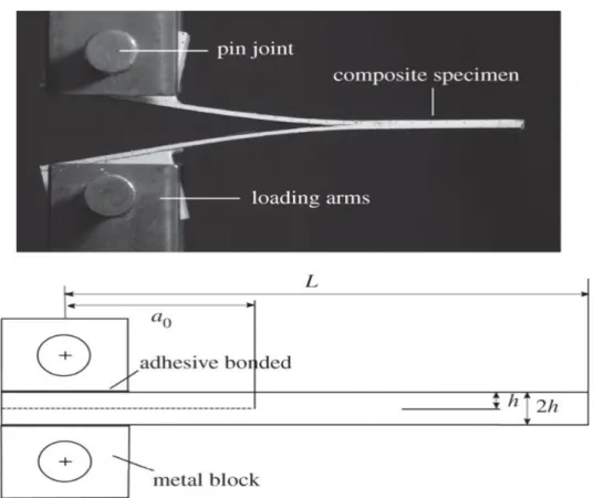
Figure 1: Specimen of the DCB test, the schematic applied load, and adhesive layer
Table 1: Material properties used for composite plies of DCB specimen simulation
Material properties
Data E11
(MPa) (MPa) E22 (MPa) E33 ʋ12 ʋ13 ʋ23 (MPa) G12 (MPa) G13 (MPa) G23 Graphite/Epoxy
ply 0◦ 130000 6500 6500 0.26 0.26 0.5 2700 2700 2700
Table 2: Material properties used for cohesive interface failure simulation
Interface properties
Data E
(MPa) G (MPa) S* (MPa) (MPa) T** (N/m) GIC (N/m) GIIC
Cohesive interface 2400 857 20 40 643 905
S*: maximum nominal interfacial strength in the normal direction T**: maximum nominal interfacial strength in the shear direction
2.1 Material failure modelling
As indicated in Figure 2, the cohesive zone model, as shown combines an initially linear elastic behaviour with strength-based failure criterion to predict the damage initiation and a fracture mechanics-based criterion to determine the damage evolution. The elastic behaviour is written in terms of an elastic constitutive matrix that connect cohesive surface tractions (t) to displacement (δ) at the interface. The initial stiffness of CZM (Figure 2, E0) defined as traction divided by separation, (units N/m3) should be chosen as high as possible to provide a reasonable stiffness. But from a numerical perspective, it cannot be infinitely large; otherwise, it leads to numerical ill-conditioning (Turon et al., 2007; Dssault System’s Simulia Corp, 2016)
unit length. Turon et al., (2007) proposed equation (1) in order to estimate the stiffness of the interface and declared that the equation is more appropriate than the other works. In this equation, E3 is the elastic modulus through-the-thickness of the composite materials t is the laminate thickness adjoining to the cohesive interface, and α is an increasing parameter normally taken about 50.
3
E K
t
(1)
As Shown in Figure 2, the point t0 refers to the beginning of materials response degradation. The t0 represents the peak values of the traction that correspond to the δ0 when the deformation is purely normal to the interface. The process of degradation begins when the traction or separation satisfies certain damage initiation criteria. Several damage initiation criteria such as maximum nominal stress (MAXE Damage) and quadratic nominal stress (QUADS Damage) are available in the ABAQUS (Dssault System’s Simulia Corp, 2016). Each damage initiation criterion also has an output variable associated with it in order to indicate whether the criterion is met. Perillo et al., (2012) have reached a better agreement between experimental results and the finite element results by using the QUADS initiation criterion.
Figure 2: Schematic damage process zone and corresponding bi-linear traction-separation law
The Quadratic nominal stress criterion is assumed to initiate when a quadratic interaction function reaches a value of one. This criterion can be represented as equation (2). In three-dimensional problems, the index n refers to normal traction and the index s and t refer to two shear traction. The Macaulay bracket (‹ ›) are used to signify that a pure compressive deformation or stress state does not initiate damage. Under single-mode loading, interface damage initiates when the traction reaches the maximum nominal interfacial strength (t0) (Dssault System’s Simulia Corp, 2016).
2 2 2
0 0 0 1
n s t
n s t
t t t
t t t
According to the strength-based failure criterion, the damage evolution would be initiated once the damage initiation condition has been met. Several constitutive models that have been proposed by the researchers for the damage evolution schemes, linear softening behaviour is usually implemented (Camanho et al., 2003). The damage evolution law describes the rate at which the material stiffness is degraded once the corresponding initiation criterion is reached. A scalar damage variable, D, represents the overall damage in the material. It initially has a value of 0 and then monotonically evolves from 0 to 1 upon further loading. The stress components of the traction-separation model are affected by the damage. According to equation (3),
t
is the stress components predicted by the elastic traction-separation behaviour for the current strains without damage (Dssault System’s Simulia Corp, 2016). As shown in Figure 2, a value of 1 of the SDEG (Overall value of the scalar damage variable D), indicates that the initiation criterion has been met at the end of the damage evolution area which corresponds to the δm. Camanho et al., (2003) proposed equation (4) in order to define the effective displacement (δm) to describe the evolution of damage under a combination of normal and shear deformation across the interface.
t 1
D t
(3)2 2 2
δm
δn
δ δ
s t (4)Damage evolution can be defined based on the energy that is dissipated as a result of the damage process. The area under the traction-separation relation (the area that shaded in Figure 2) is equal to the fracture toughness energy, Gc. Although the scalar damage variable (D) is derived from this parameter, the fracture energy (Gc) is the most important parameter which can be determined by means of some standard experimental tests.
2.2 Solution method
The simulation of delamination based on CZM approach, is possible to be solved by an explicit or implicit algorithm available in ABAQUS. The ABAQUS/Standard general-purpose solver uses a traditional implicit integration scheme to solve finite element analyses. On the other hand, the ABAQUS/Explicit which uses an explicit central-difference time integration rule applies an explicit integration scheme to solve highly nonlinear transient dynamic and quasi-static analyses. The simulation of delamination based on CZM approach is involves softening in the material response, and lead to convergence difficulties in an implicit solution procedure in ABAQUS/Standard. Convergence difficulties may also occur during unstable crack propagation when the available energy is higher than the fracture toughness of the material (Dssault System’s Simulia Corp, 2016).
Khoramishad et al. (2010) uses standard solver of ABAQUS to simulate the single lap joints according to the CZM approach. Cerioni (2009) offers explicit solver in order to obtain the finite element solution for avoiding convergence problems and numerical instabilities. In the earlier work (Khalili et al., 2011), it was found that in an explicit scheme, the analysis cost rises only linearly with problem size, whereas the cost of solving the nonlinear equations associated with implicit integration rises more rapidly than linearly with problem size. Therefore, ABAQUS/Explicit is attractive for very large problems.
2.3 Type of elements
Based on plane strain assumption, the simulation of delamination on DCB composite could be analysis with two-dimensional elements. Mi et al., (1998) applied a three-two-dimensional analysed and indicated that the 2D plane strain formulation gave a very reasonable approximation versus three-dimensional analysis. While Alfano and Crisfield (2001) strictly declared that a 3D analysis would be needed since the delamination front was not precisely a straight line.
Conventional shell, continuum shell and solid elements are available options in ABAQUS for modelling the composite structures. While cohesive behaviour is used in conjunction with stacked conventional shell elements, the specialized contact formulation may lead to approximate normal contact forces. This may induce approximate transverse shear behaviour in the stacked shells which affect the bending behaviour of the stack. Continuum shells should be used instead of conventional shells in such modelling scenarios (Dssault System’s Simulia Corp, 2016).
2.4 Cohesive surfaces versus cohesive elements
Some researchers like Turon et al., (2007) used cohesive elements in CZM approach, but others like Gonzalez (2011), used both of cohesive elements and cohesive surfaces in CZM approach and concluded that the use of cohesive surfaces resulted in improving the runtime of the analysis. On the other hand, it can yield to large runtime analysis because contact algorithms are computationally heavy especially when the connected mesh are highly refined.
2.5 Verification and discussion on simulation method
This section briefly describes the finite element (FE) simulation of the delamination on DCB composite specimen based on CZM approach. In this study, the FE simulation, has been done with the finite element package ABAQUS version 2016 and is performed on a computer with 3.2 GHz Intel® Corei7, with 8.00 GB RAM.
According to Table 1, the material modelling of composite ply in the present FE simulation has been done by linear elastic with engineering constant option that is available in ABAQUS. The CZM approach is used to simulate the interface failure modelling of cohesive layer between two beams of the specimen. According to Table 2, the magnitude of the initial stiffness of the cohesive element (Figure 2, E0) has been imported to the ABAQUS and it does not need to be divided by the cohesive thickness. For defining the quadratic nominal stress (QUADS Damage) criterion, the S and T which are taken from Table 2 are considered as the maximum nominal interfacial strength (t0) in the two directions (normal and shear). Also according to Table 2, the fracture energies GIC, and GIIC are imported to ABAQUS to define the modes I and II for simulation of the interlaminar fracture toughness in cohesive interface.
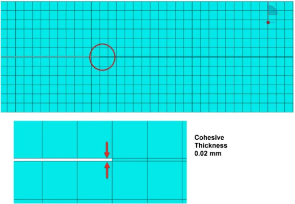
The 4 nodes, two-dimensional continuum plane strain elements (CPE4R) and the 4 nodes, two-dimensional cohesive elements (COH2D4) are used in the FE simulation of the composite specimens and the cohesive interface. A very refined mesh using an element length of 0.25 mm was used for both solid and cohesive elements and is constant for all the models (6720 elements of type CPE4R and 360 elements of type COH2D4). This element length is recommended by Cerioni (2009) and as shown in Figure 3, only one cohesive element in the cohesive interface was put.
Figure 3: Mesh used in the FE simulation and cohesive thickness element size
Figure 4: The boundary conditions of FE simulation
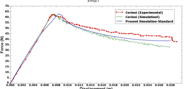
In this case study, the present simulation results gained by standard solver of ABAQUS are compared with the available experimental and numerical results by the Cerioni (2009). As shown in Figure 5, there is a good correspondence between the elastic branches of the three curves. Also, the prediction of the onset of the delamination looks adequate. But some mismatch was observed between the present simulation and the results of reference (Cerioni, 2009) in onset of the delamination. Furthermore, there is a difference in the propagation branch of the simulation model stiffness which has been decreased more quickly in respect of the experimental results. In addition, better correspondence was observed with experimental results in the present simulation versus simulation of Cerioni (2009).
Figure 5: Comparison of contact force variation as a function of displacement for delamination on DCB composite specimen between the present FE simulation and the results of Cerioni (2009)
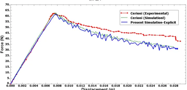
Figure 6: Comparison of contact force variation as a function of displacement for delamination on DCB composite specimen between the present FE simulation with explicit solver and the results of Cerioni (2009)
As mentioned earlier in section 2.3, a 3D analysis would be needed since the delamination front is not precisely a straight line (Alfano and Crisfield, 2001). In this study the composite specimen uses the SC8R element for investigation the effect of 3D modelling in delamination. According to the earlier work (Khalili et al., 2011), SC8R elements should be used in thick plates and shells. The SC8R or S4R elements are an eight-node continuum shell and four-node conventional shell elements with reduced integration, respectively.
In case of modelling, cohesive behaviour is possible to be used in conjunction with stacked conventional shell elements. Depending on the load case, the specialized contact formulation may lead to approximate normal contact forces, which in turn may induce the approximate transverse shear behaviour in the stacked shells and consequently affect the bending behaviour of the stack. For increasing accuracy in such modelling scenarios, continuum shells should be used instead of conventional shells (Dssault System’s Simulia Corp, 2016).
As mentioned earlier in section 2.4, cohesive surfaces like cohesive elements could be used in CZM approach simulation. Also unlike to 2D modelling, the 3D modelling leads to large runtime analysis. Therefore the cohesive surfaces should be uses in 3D modelling in order to improve the analysis runtime.
In the cohesive surface method, the initial stiffness magnitude of the cohesive surface that should be imported to the ABAQUS is different from the magnitude for the cohesive element. In addition it should be divided by the cohesive thickness and does not need to multiply to 50, according to the equation (1).
Figure 7: Comparison of force variation as a function of displacement for delamination on DCB composite specimen between the present FE simulation with explicit solver and 3D modelling and the results of Cerioni (2009)
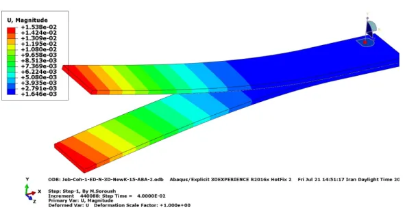
Figure 8: Non-symmetric pattern of the displacement contour in the DCB composite specimen
3 SIMULATION OF IMPACT ON LAMINATED COMPOSITE PLATES BASED ON CZM AND PDM
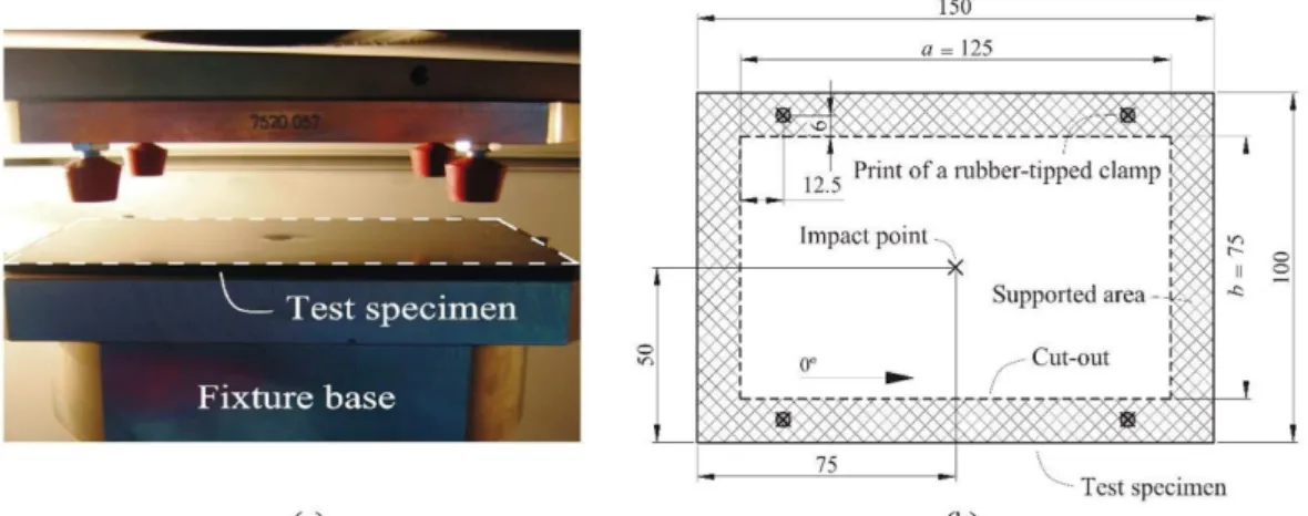
Figure 9: (a) Test specimen and fixture base and (b) detail of support area and clamping points of the specimen
Table 3: Ply properties of AS4/8552 Carbon/Epoxy
Material properties
Elastic
(Gpa) 128 E11 7.63 E22 4.36 G12
Damage initiation
(Mpa) 2300
X
TX
C 1531Y
T 26 199.8Y
C S78 LDamage evolution
(N/mm)
F
81.5 TF
C 106.3M
0.28 TM
0.79 CTable 4: Interface properties
Interface properties
Elastic properties E=7.63 Gpa ʋ=0.45 Mode I Strength
(Mpa)
1 43.8
2 26
3 26Fracture toughness
(N/mm)
G
Ic0.28 IIc
G
0.79 IIIc
G
0.79
3.1 Material failure modelling
In this study, the material failure modelling is based on the progressive damage model that is used mainly to obtain the overall response of the composite laminates. A typical PDM consists of three steps: linear elastic stress analysis, failure analysis, and property-degrading material state variable. There are many material models that can be used to predict the behaviour of composite laminates. Progressive damage model in ABAQUS is assumed to be linearly elastic. It is intended that the model predicts the behaviour of composite laminates for damage which can be initiated without a large amount of plastic deformation. The initiation criteria are used to predict the onset of damage and the damage evolution law is based on the energy dissipated during the damage process and linear material softening (Dssault System’s Simulia Corp, 2016).
The ABAQUS anisotropic damage model is based on the work of Hashin and Rotem (1973), Hashin (1981) and Camanho et al., (2003). In ABAQUS, the damage initiation criteria for fiber composite laminates are based on Hashin's theory. There are four different damage initiation criteria in ABAQUS (Dssault System’s Simulia Corp, 2016) as follows:
• fiber rupture in tension
• fiber buckling and kinking in compression
The equations for these damage initiation criteria are listed in the following equations (5-8). Tensile or compressive damage can be initiated in the fiber or the matrix when the respective F equals one.
2 2
11 12
11
0
ft T LFiberTensionthat
F
X
S
(5)2 11
11
0
fc cFiber compresionthat
F
X
(6)2 2
22 12
22
0
mt T LMatrixTensionthat
F
Y
S
(7)2
2 2
22 22 12
22 0 2 [ 2 1]
C c
m T T C L
Y
Matrix compresion that F
S S Y S
(8)
In the above equations,
X
T,
,X
c ,Y
T,Y
C, SL andSTdenotes the longitudinal tensile strength, the longitudinal compressive strength, the transverse tensile strength, the transverse compressive strength, the longitudinal shear and transverse shear strength respectfully. Also, is a coefficient that determines the contribution of the shear stress to thefiber tensile initiation criterion. In addition
11 12, and
22 are components of the effective stress tensor which is usedto evaluate the initiation criteria. The initiation criteria presented above can be specialized to obtain the model proposed
in Hashin and Rotem (1973) by setting
0
and2
C TY
S
, or the model proposed in Hashin (1981) by setting
1
. Prior to damage initiation, the material in ABAQUS Progressive damage modelling is linearly elastic with the stiffness matrix of a plane stress orthotropic material. Thereafter, the effect of damage is taken into account by reducing the value of stiffness coefficients. If any of the damage variables become one, stress can no longer be supported in the respective direction because the stiffness goes to zero. The response of the material is computed by the equation (9), where is the strain andC
d is the damaged elasticity matrix (Dssault System’s Simulia Corp, 2016).d
C
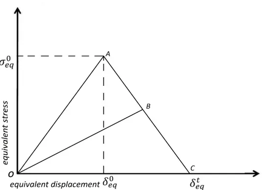
(9)In a damage evolution model in ABAQUS PDM, it's required to predict the material response in each of the four failure modes as loading increases or unloading. As it's indicated in Figure 10, these should be beyond the point of initial damage as linear damage evolution. Prior to damage initiation the positive slope of the stress-displacement curve corresponds to linear elastic material behavior. Whereas the negative slope is achieved by evolution of the respective damage variables after damage initiation. To relieve mesh dependency during material softening, ABAQUS introduces a characteristic length into the formulation. So the damage evolution is expressed as a stress-displacement relation. In Figure 10,
eq0 (initial equivalent displacement) intersected
eq0 (initial equivalent stress) at the point A. This point isthe damage initiation criterion which met for each failure mode.
eqt is the displacement at which the material is fullydamaged.
Figure 10: Equivalent stress versus equivalent displacement in linear damage evolution
3.2 Solution method
As mentioned in the earlier work (Khalili et al., 2011), the simulation of impact on composite laminates, is possible to be solved by both explicit and implicit solver of ABAQUS, but the ABAQUS/Explicit is the appropriate choice to solve highly nonlinear transient dynamic and progressive damage modelling (Dssault System’s Simulia Corp, 2016). Also as it is mentioned in section 2.2, the ABAQUS/Explicit is attractive for very large problems.
3.3 Contact modelling
Hard contact law is one of the contact laws that is available in ABAQUS. In this contact method, the contact constraint is applied when the clearance between two surfaces becomes zero. There is no limit in the contact formulation on the magnitude of contact pressure which can be transmitted between the surfaces. The surfaces are separated when the contact pressure between them becomes zero or negative, then the constraint is removed. The contact force is a function of the penetration distance. And it is applied to the slave nodes to oppose the penetration while equal and opposite forces act on the master surface at the penetration point. When using hard contact, it is still possible to make master surface penetrate into the slave surface by pure master-slave algorithm as indicated in Figure 11 (Dssault System’s Simulia Corp, 2016).
Figure 11: Master surface penetrate into the slave surface of a pure master-slave contact pair
element-based surfaces contact each other. Balanced master-slave weighting means that the corrections produced by both sets of contact calculations are weighted equally. The penalty contact algorithm for balanced master-slave contact surfaces computes contact forces that are linear combinations of the calculated pure master-slave forces. One set of forces is calculated by considering one surface as the master surface, and the other forces are calculated by considering the same surface as the slave surface (Dssault System’s Simulia Corp, 2016). As mentioned in section 2.4, it is possible to use both cohesive element and cohesive surfaces for defining cohesive behaviour between tow laminates of composite plate. But in the 3D modelling, cohesive surfaces are preferable due to their low-cost analysis.
3.4 Type of elements and mesh convergence study
Conventional shell, continuum shell and solid elements are available options in the modelling of the composite laminates in ABAQUS. The choice of an element type used for the plates or shells as target structures depends on their side to thickness ratio as well as the impactor velocity. Increasing the thickness of target and impactor velocity lead to increase in the shear deformation.
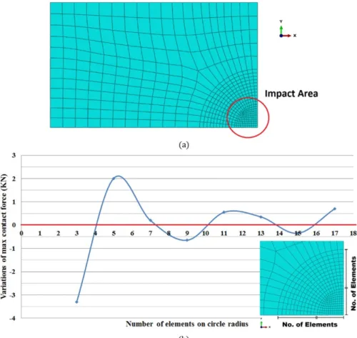
In order to obtain the optimum number of elements, an analysis of the number of elements sensitivity is performed. In Figure 12 mesh pattern of the circular area surrounding the contact region and the convergence study of the number of elements are shown. This study indicated that the element number of 15 in edges of circular impact area is the optimum number of elements.
Figure 12: Convergence study of element numbers (a) mesh pattern of the circular area surrounding the contact region (b) variation of maximum contact force vs. number of element
3.5 Verification and discussion on simulation method
Similar to the section 2 of this study, the ABAQUS version 2016 is used for simulation of the impact on laminated composite plates. The simulation is performed on the same computer mentioned in the previous section.
The material modelling of composite ply has been done by linear elastic with lamina option that is available in ABAQUS. Due to the plane stress condition that is used for SC8R elements, only the values of
E
11,E
22, ʋ12,G
12,13
Table 3 of the present FE simulation, the requared materials properties are defined assuming
G
13 is equal toG
12 and23
G
is equal to 2 123G .
As mentioned earlier in section 3.1, Hashin's damage initiation criteria parameters are required in the PDM approach that is used for intralaminar failure modelling of laminated composite. According to the Table 3, the mentioned parameters are defined as damage initiation, assumingST is equal to 2
3SL. In order to model progressive damage, the
energy dissipated due to failure (Gc) of each failure mode should be imported to ABAQUS. The
F F M
T, ,
C T andM
Care taken from Table 3, as fracture energy in the fiber and matrix in tension and compression mode.
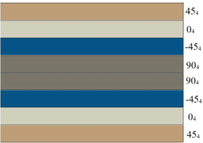
According to Table 4, the interlaminar failure properties of interfaces are defined. Also the procedure that is used in this section is similar to section 2.5 for cohesive zone modelling. In order to modelling the interlaminar failure of interfaces in the present laminate configuration [454/04/-454/904]s the clustering ply was chosen. Therefore the delamination in stacking ply with the same fiber orientation (clustering) is considered and the interlaminar failure in inner layer of any cluster is ignored. As indicated in Figure 13, seven cohesive surfaces duo to low-cost analysis are modelled according to the CZM procedure by using the properties of Table 4.
Figure 13: Cohesive surfaces in laminate configuration [454/04/-454/904]s
Based on the preferences of explicit solver mentioned earlier in section 3.2, ABAQUS/Explicit is used in this study for simulating the impact phenomena. The hard contact law is chosen for being applied as the clearance between two surfaces becomes zero. The impactor and the target are set as the master and slave surfaces, respectively with penalty contact algorithm of balanced master-slave contact surfaces. The impactor was modelled as deformable body with element of C3D8R and the laminated composite are meshed using SC8R elements. As mentioned earlier in section 3.4, the optimum number of elements (12224 elements of type SC8R and 4025 elements of type C3D8R) are obtained based on the mesh convergence study,
According to section 3, three case studies with different level of impact energies were chosen to verify the present FE simulation procedure. Therefore, impactor with initial velocities of 3.93, 3.38 and 2.78 m/s were simulated.
Figure 14: FE Simulation and Experimental contact force variation as a function of time for a composite plate under impact kinetic energy of 19.3 J
Figure 16: The comparison of contact force variation as function of impactor displacement for a composite plate under impact kinetic energy of 19.3 J
The present results for the contact force history with impactor velocity of 3.38 m/s and kinetic energy of 28.6 J is shown in Figure 17, and compared with experimental and numerical results of Gonzalez (2011). It should be mentioned Gonzalez (2011) has only reported the contact force history for this level of impact energy.
Figure 17: FE Simulation and Experimental contact force variation as a function of time for a composite plate under impact kinetic energy of 28.6 J
Figure 18: FE Simulation and Experimental contact force variation as a function of time for a composite plate under impact kinetic energy of 38.6 J
Figure 19: FE Simulation and Experimental energy dissipation variation of impactor as a function of time for a composite plate under impact kinetic energy of 38.6 J
4 CONCLUSION
In this study, a reliable, low-cost and simple method is provided based on ABAQUS/Explicit package by considering damage in laminated composite plates under transverse impact loadings. The best procedure is proposed which can serve as benchmark method in damage modeling of composite structures under high velocity impact for future investigations. First, the simulation of delamination on DCB composite specimen is verified based on CZM approach. In addition, materials model, solution method, element type and method of cohesive definition are considered. It is observed that, less CPU run-time is required for simulation of delamination problems 2D modelling. Furthermore, cohesive surface rather than cohesive element should be used in 3D modelling for improving the analysis runtime. Contrary to cohesive surface, there is no need to divide the initial stiffness of the cohesive element -which should be imported to the ABAQUS- by the cohesive thickness
It can be declared that, explicit solver of ABAQUS is the appropriate choice for modelling progressive damage and cohesive zone. In addition ABAQUS/Explicit is capable to solve highly nonlinear transient dynamic and it is attractive for very large problems.
In this study, the simulation of impact on laminated composite plates based on CZM and PDM are verified by the experimental and numerical results available in the literature.
By considering damage evolution behaviours of matrix and fiber cracking and interface delamination in three case studies with different levels of impact energies, our simulation results have an appropriate correspondence with the results of similar works especially in the aspect of force-time, force-displacement and energy time histories curves. According to the simulation results, the delamination in clustering ply is significant but the interlaminar failure in an inner layer of any cluster could be ignored.
Like to Gonzalez (2011), we have used ABAQUS finite element simulation; unlike to him, our simulation results are more accurate -about 12 percent better correspondence in maximum contact force- than his simulation results especially in higher impactor velocity. On the other hand, our results correspond to his experimental results appropriately. Finally, the proposed method can serve as a benchmark for simple impact simulation of composite structures based on CZM and PDM in the future investigations, such as optimization study and engineering application of composite laminates under impact.
References
Abrate, S. (1998). Impact on composite structure, Cambridge University Press, New York, USA.
Cantwell, W. J., and Morton, J. (1989). Comparison of the low and high velocity impact response of CFRP. Composites, 20: 545-551.
Guoqi, Z., Goldsmith, W., and Dharan, C. H. (1992). Penetration of laminated Kevlar by projectiles—I. Experimental investigation. International Journal of Solids and Structures, 29(4), 399-420.
Cheng, W. L., Langlie, S., and Itoh, S. (2003). High velocity impact of thick composites. International journal of impact engineering, 29: 167-184.
Silva, M. A., Cismaşiu, C., and Chiorean, C. G. (2005). Numerical simulation of ballistic impact on composite laminates. International Journal of Impact Engineering, 31: 289-306.
Cerioni, A. (2009). Simulation of delamination in composite materials under static and fatigue loading by cohesive zone models, Ph.D. Thesis, Universita'degli Studi di Cagliari, Cagliari
Zhao, G., Cho, C., Lu, S., et al., (2010). Experimental study on impact resistance properties of T300/epoxy composite laminates. Journal of composite materials, 44: 857-870.
Khalili, S. M. R., Soroush, M., Davar, A., et al., (2011). Finite element modeling of low-velocity impact on laminated composite plates and cylindrical shells. Composite Structures, 93: 1363-1375.
Ramadhan, A. A., Talib, A. A., Rafie, A. M., et al., (2013). High velocity impact response of Kevlar-29/epoxy and 6061-T6 aluminum laminated panels. Materials & Design, 43: 307-321.
Chou, S. C., Orringer, O., and Rainey, J. H. (1977). Post-Failure Behavior of Laminates: II—Stress Concentration. Journal of Composite Materials, 11: 71-78.
Maimí, P., Camanho, P. P., Mayugo, J. A., et al., (2007). A continuum damage model for composite laminates: Part I– Constitutive model. Mechanics of Materials, 39: 897-908.
Camanho, P. P., Maimí, P., and Dávila, C. G. (2007). Prediction of size effects in notched laminates using continuum damage mechanics. Composites science and technology, 67: 2715-2727.
Zou, Z., Reid, S. R., Li, S., and Soden, P. D. (2002). Modelling interlaminar and intralaminar damage in filament-wound pipes under quasi-static indentation. Journal of composite materials, 36: 477-499.
Tan, S. C. (1991). A progressive failure model for composite laminates containing openings. Journal of Composite Materials, 25: 556-577.
Shokrieh, M. M., (1996). Progressive fatigue damage modeling of composite materials. Ph.D. Thesis, McGill University, Montreal
Camanho, P. P., and Matthews, F. L. (1999). A progressive damage model for mechanically fastened joints in composite laminates. Journal of Composite Materials, 33: 2248-2280.
Turon, A., Davila, C. G., Camanho, P. P., et al., (2007). An engineering solution for mesh size effects in the simulation of delamination using cohesive zone models. Engineering fracture mechanics, 74: 1665-1682.
Barenblatt, G. I. (1962). The mathematical theory of equilibrium cracks in brittle fracture. Advances in applied mechanics, 7: 55-129.
Dugdale, D. S. (1960). Yielding of steel sheets containing slits. Journal of the Mechanics and Physics of Solids, 8: 100-104.
Hillerborg, A., Modéer, M., and Petersson, P. E. (1976). Analysis of crack formation and crack growth in concrete by means of fracture mechanics and finite elements. Cement and concrete research, 6: 773-781.
Khoramishad, H., Crocombe, A. D., Katnam, K. B., et al., (2010). Predicting fatigue damage in adhesively bonded joints using a cohesive zone model. International Journal of fatigue, 32: 1146-1158.
Dssault System’s Simulia Corp (2016). ABAQUS 2016 User's Manual. Providence. RI. USA.
Camanho, P. P., Davila, C. G., and De Moura, M. F. (2003). Numerical simulation of mixed-mode progressive delamination in composite materials. Journal of composite materials, 37: 1415-1438.
Perillo, G., Vedvik, N. P., and Echtermeyer, A. T. (2012). Numerical analyses of low velocity impacts on composite. Advanced modelling techniques. In Proceedings of the Simulia customer conference.
Mi, Y., Crisfield, M. A., Davies, G. A. O., and Hellweg, H. B. (1998). Progressive delamination using interface elements. Journal of composite materials, 32: 1246-1272.
Hashin, Z., and Rotem, A. (1973). A fatigue failure criterion for fiber reinforced materials. Journal of composite materials, 7: 448-464.