Abstract – The objective of this study was to validate a new stabilometric force platform (SFP). For this, three steps have been established: a) to determine the force threshold to reach an acceptable level of accuracy of the centre of pressure (CoP) measurement by the application of single point load; b) to determine the accuracy of the CoP measurement in the application of distributed load simulating the human feet; c) to verify the concurrent validity of the SFP by comparing it with a commercial force platform (FP). The tests per-formed in steps “a” and “b” were conducted by applying loads on the SFP using a universal testing machine. In the application of single point load, the mean force threshold presented by the SFP was 315.6 ± 140.5 N. The CoP measurement error in the points near the centre of the SFP was 1.04 ± 0.80 mm in medial-lateral (ML) and 1.31 ± 0.99 mm in anterior-posterior (AP) direction. In the points near the edges of the plate, the error was 2.03 ± 0.91 mm (ML) and 1.54 ± 0.96 mm (AP). In the test with distributed loads, errors of less than 1 mm were found. Additionally, no differences were found in the CoP parameters between SFP and the FP. The CoP measurement signal presented high correlation between both equipments in AP (r = 0.997 ± 0.001) and ML (r = 0.988 ± 0.003) directions. These indings suggest that the SFP can be used in scientiic investigations of balance in quiet standing. Key words: Biomechanics; Postural balance; Instrumentation.
Resumo – O objetivo deste estudo foi validar uma nova plataforma de forças estabilométrica (PFE). Para isso, três etapas foram estabelecidas: a) determinar o limiar de carga para chegar a um nível aceitável de exatidão da medida do centro de pressão (CP) pela aplicação de cargas pontuais; b) determinar a exatidão da medida do CP na aplicação de cargas distribuídas que simulam os pés humanos; c) veriicar a validade concorrente da PFE comparando-a com uma plataforma de forças comercial (PF). Os testes das etapas “a” e “b” foram realizados pela aplicação de cargas sobre a PFE, utilizando uma máquina de ensaios universal. Na etapa de aplicação de carga pontual, a média do limiar de carga apresentado pela PFE foi de 315.6 ± 140.5 N. Os erros de medida do CP nos pontos próximos ao centro da PFE foram de 1.04 ± 0.80 mm na direção medio-lateral (ML) e 1.31 ± 0.99 mm na direção ântero-posterior (AP). Nos pontos próximos aos cantos da chapa, foram encontrados erros de 2.03 ± 0.91 mm (ML) e 1.54 ± 0.96 mm (AP). No teste com cargas distribuídas, os erros foram menores que 1 mm. Adicionalmente, não foram encontradas diferenças nos parâmetros do CP entre a PFE e a PF. O sinal do CP apresentou alta correlação entre os dois equipamentos, tanto na direção AP (r = 0.997 ± 0,001) quanto na direção ML (r = 0.988 ± 0,003). Os resultados sugerem que a PFE pode ser utilizada em estudos cientíicos do equilíbrio em postura ereta.
Palavras-chave: Biomecânica; Equilíbrio postural; Instrumentação. 1 Universidade do Estado
de Santa Catarina. Cen-tro de Ciências da Saúde e do Esporte Laboratório de Instrumentação. Flo-rianópolis, SC. Brasil 2 Université d’Auvergne Institut Universitaire de Technologie. Clermont--Ferrand. France
Received: 06 December 2010 Accepted: 03 March 2011
CC $ =
1 1 1 1 1 2 1,2
Jonathan Ache Dias Lucas Borges Daniela Junckes da Silva Mattos Marcelo Diederichs Wentz Susana Cristina Domenech Philippe Kauffmann Noé Gomes Borges Junior
Validity of a new stabilometric force platform for
postural balance evaluation
Validity of a new stabilometric force platform Dias et al.
INTRODUCTION
Stabilometric evaluation involves the analysis of the centre of pressure (CoP), which relects the net motor pattern at the ankle and consequently the response of the central nervous system to cor-rect the imbalance of the body’s center of mass1,2. Several studies3-7 use the CoP displacement as an indication of stabilization mechanisms and postu-ral control during standing position.
Force platforms (FP), which are complex and precise systems8, are commonly used to measure the CoP. However, these equipments have a high cost, especially when imported by research groups that have limited inancial resources. In order to make it possible for our group to conduct balance researches in quiet standing, a less expensive alternative was used by building a stabilometric force platform (SFP), which calculates the CoP by the measurement of the vertical reaction force, like others with the same principle found in lit-erature1,9,10. However, a validation process of this system had to be carried out, so that it could be used in scientiic studies.
Regarding the FP validity, the parameters that are usually veriied are accuracy11-14 and force threshold15 of the CoP measurement. In general, these parameters are veriied by the application of single point load14,16, by the application of distrib-uted loads14,17 and by comparison with a commercial FP1,18. Therefore, the objective of this study was to validate the SFP. For this, three steps have been established: a) to determine the force threshold to reach an acceptable level of accuracy of the CoP measurement by the application of single point load; b) to determine the accuracy of the CoP measurement in the application of distributed load simulating the human feet; c) to verify the concurrent validity of the SFP by comparing it with a commercial FP.
METHODS
The stabilometric force platform
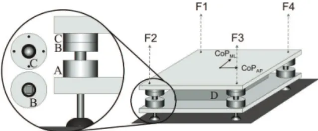
The SFP is composed of two parts: the dynamome-tric structure and the data acquisition system. The dynamometric structure (Figure 1) was developed using two rectangular steel (AISI 1020) plates (0.5 x 0.39 x 0.0125 m), and four uniaxial load cells with capacity of up to 1 kN (Gefran® TU-K1C) placed in each corner of the plates, equidistant 0.03 m from the edges. The usable area of the dynamo-metric system corresponds to the rectangular area
that has the centres of the four load cells as corners. A contact system was created to connect the two plates (Figure 1). This structure was designed to ensure that only four points of the upper plate make contact, one in each corner (approximately 1 mm2), with the load cells placed on the lower plate, avoiding the interference of horizontal forces, thus minimizing the hysteresis effects and errors in vertical reactions.
Figure 1. Schematic overview of the stabilometric force platform structure. A contact system is formed by parts A, B and C. A is the load cell attached to the lower plate. Part B is attached to the load cell, which contains a contact surface (manufactured with widia steel) to receive the metal sphere placed between parts B and C, and C is attached to the upper plate. D is the structure containing the data acquisition system; CoP is the centre of pressure; AP, anterior-posterior direction; ML, medial-lateral direction; F, vertical component force of each load cell.
The data acquisition system consists of a DC four-channel ampliier and a microcontroller system with 10 bits A/D of resolution. The system is sup-plied by rechargeable battery. The USB port is used for the data transmission to the PC. Software for data acquisition was developed for this equipment. In triaxial FP, as the AMTI®, the CoP location, in the anterior-posterior (AP) and medial-lateral (ML) directions, is usually calculated using the following equations15:
CoPAP = MML / FZ (1)
CoPML= - MAP / FZ (2)
where MML and MAP are the moments around medial-lateral and anterior-posterior components respectively and Fz is the vertical component of the force. However, for the SFP, which has four uniaxial load cells arranged in a rectangular shape, FZ is considered to be equal to the sum of vertical reaction forces of each load cell. Considering that ∑ Moments = 0 and ∑ Forces = 0, the CoP must be located exactly at the centre of the system. Thus, the CoP location was calculated by the following equations19:
the vertical reaction force of each load cell, Fz is the sum of F1, F2, F3 and F4. This equation is ap-propriated to systems with four uniaxial load cells arranged in a rectangular shape.
Force threshold
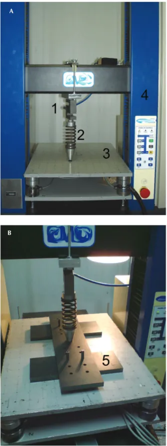
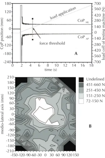
This test was performed to verify the sensitivity (force threshold) of the CoP measurement to the load applied. To do so, a test grid, with squares of 3 cm, was carefully drawn using a digital calliper (error ± 0.05 mm) performing a matrix (11 x 15) of 165 points on the usable area of the SFP surface, which were considered as the reference positions. The test consisted of the application of single point dynamic loads from 0 to 700 N at 100 mm/s on each point of the test grid using an universal testing machine (DL-3000, EMIC, Brazil), a load cell with capacity of up to 5 kN and a mechanical structure that applies the load in 1 mm2 (Figure 2). The data was acquired at a sampling frequency of 100 Hz. The force threshold was the minimal load necessary for the CoPmeasured to reach the ref-erence position on the test grid (CoPpredicted) with standard deviation (SD) of up to 3 mm in both directions. The error was calculated by subtracting the CoPmeasured from the CoPpredicted. The SD range was irst used by Chockalingam et al.15 and it was considered as an acceptable level of accuracy for the application of single point load. Figure 3 shows the method to establish the force threshold. The sensitivity of the CoP measurement to the load applied on the 165 points drawn on the test grid was classiied into the following categories: 72-150 N; 151-250 N; 251-450 N; 451-650 N and undeined. The mean error of the CoPML and CoPAP was cal-culated for each of the categories.
Distributed load test
The tests were performed to determine the accu-racy of the CoP measurement during the applica-tion of distributed load to simulate the load applied by the human feet in stabilometric evaluations. For this, the same structure of the previous test was used, with the addition of two metal feet positioned on the platform (Figure 2). With this test, the CoP location was measured for ive seconds with the application of a static load. This experiment was performed in four distance conditions between the two metal feet (60, 120, 180, 240 mm). The feet were aligned in relation to the center of SFP so that the expected CoP location (CoPpredicted) was
Validity of a new stabilometric force platform Dias et al.
and standard deviation of CoPAP and CoPML loca-tion in each condiloca-tion were calculated to determine the accuracy of the CoP measurement.
Concurrent Validity
In this step, the SFP was compared with a previ-ously calibrated AMTI® FP (Model OR6-7-2000, Advanced Mechanical Technology, INC, USA), as performed by Grabiner et al.1. For this, the SFP was placed on the center of the FP and a trigger was used to start the instruments with synchro-nism. Five volunteers (30.8 ± 11.5 years old; height of 1.71 ± 0.09 m; body mass of 69.6 ± 15.1 kg) participated of this experiment. The purpose and procedures were explained to each subject, who signed an informed consent form prior to their participation. All the procedures were approved by the Ethics Research Committee involving human beings (Santa Catarina State University, protocol number 199/2008).
The subjects were instructed to stand barefoot and quietly on the SFP for 20 seconds, with arms relaxed on the side of their bodies and to look at a target placed at a distance of 1.5 m from the subject, at eye level. The CoP was acquired at a sampling frequency of 100 Hz in both equipments. The following stabilometric CoPAP and CoPML parameters were calculated for each subject with algorithms implemented in the Scilab software (v. 4.1.2; INRIA, France): root mean square (RMS), amplitude (AMP), mean velocity (MV) and area of the 95% conidence ellipse (AREA). To bet-ter analyze the CoP signal, the mean signal was removed and iltered in a low-pass ilter (4th order Butterworth, 8Hz cut-off). Additionally, in the equations used to calculate the CoP of the AMTI® FP (equations 1 and 2), the height of the SFP was considered. The Wilcoxon test was used to compare the stabilometric parameters between SFP and FP. Later, the correlation between the raw CoP signal (CoPAP and CoPML) of both systems (SFP and the FP) for each subject was veriied by the Pearson’s correlation test. All statistical analyses were per-formed using SPSS for Windows (v. 14; SPSS Inc., USA), at a signiicance level of 0.05.
RESULTS
The force threshold of all points ranged from 73.1 N to 659.5 N (mean of 315.6 ± 140.5 N); 7.8 % of those presented force threshold of 72-150 N with CoPML error = 1.04 ± 0.80 mm and CoPAP error = 1.31 ± 0.99 mm; 20.7 % presented force threshold of 151 – 250 N
with CoPML error = 1.67 ± 0.95 mm and CoPAP error = 1.60 ± 0.96 mm; 34.5 % presented force threshold of 251 – 450 N with CoPML error = 1.81 ± 0.95 mm and CoPAP error = 1.66 ± 0.90 mm; 12.7 % presented force threshold of 451 – 660 N with CoPML error = 2.03 ± 0.91 mm and CoPAP error = 1.54 ± 0.96 mm and in 24.2%, the force threshold could not be established (error > 3 mm). Figure 3 shows the distribution of all points of the test grid on the force threshold catego-ries. According to Figure 3, when the point is closer to the edges of the platform, the CoP measurement error and the force threshold tend to increase.
Figure 3. A) Illustration of the method used to establish the force threshold. The CoPML and CoPAP location during the application of the dynamic load (from 0-700 N) on the refer-ence position, (30,-30) mm, of the test grid is represented. In this example, the minimal load necessary for the CoP position to reach CoPML of 30 ± 3 mm was 150 N and to reach CoPAP of - 30 ± 3 mm was 140 N; therefore, the force threshold was 150 N. B) Contour plot of the 165 points of the matrix indicat-ing the sensitivity (force threshold) in the different areas of the SFP in the application of the single point load.
distributed load test.
Distance between the metal feet (mm)
CoPAP (mm) CoPML (mm)
60 0.24 ± 0.21 0.37 ± 0.20
120 0.35 ± 0.26 0.34 ± 0.32
180 0.37 ± 0.31 0.84 ± 0.48
240 0.17 ± 0.13 0.72 ± 0.36
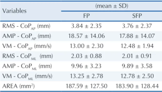
The results of the concurrent validity test betwe-en FP and SFP showed that the stabilometric para-meters of the CoP measured by both systems do not present signiicant differences, as shown in table 2.
Table 2.Comparison of the stabilometric parameters between AMTI® Force platform (FP) and Stabilometric force platform (SFP).
Variables (mean ± SD)
FP SFP
RMS - CoPAP (mm) 3.84 ± 2.35 3.76 ± 2.37
AMP - CoPAP (mm) 18.57 ± 14.06 17.88 ± 14.07 VM - CoPAP (mm/s) 13.00 ± 2.30 12.48 ± 1.94
RMS - CoPML (mm) 2.03 ± 0.88 2.01 ± 0.91 AMP - CoPML (mm) 9.96 ± 3.23 9.89 ± 3.58 VM - CoPML (mm/s) 13.25 ± 2.78 12.78 ± 2.50 AREA (mm2) 187.59 ± 127.50 183.90 ± 128.44
Root mean square (RMS), amplitude (AMP), mean velocity (MV) and area of the 95% confidence ellipse (AREA).
Additionally, the raw CoP signal of FP and SFP presented a high correlation for all subjects in the AP (r = 0.997 ± 0,001) and ML (r = 0.988 ± 0,003) direction.
DISCUSSION
In relation to the force threshold obtained in the application of the single point load, the SFP system showed good sensitivity, however, it was not as sensitive as the commercial FP analyzed by Chockalingam et al.15, which presented a verti-cal force threshold ranging from 50.5 to 113.7 N, considering the entire area of the FP. For the SFP, it was observed that the sensitivity is higher along the center of the plate, ranging from 72 to 150 N (Figure 3) and lower as it approaches the limits of the usable area, which is a characteristic found by other authors in strain-gauge and piezoelectric FP14,15. The CoP location error also seems to in-crease in the points farther from the center of the SFP, and the results indicate that the highest error in the majority of points occurs in the ML direc-tion, except for the points in the threshold category
with the results found by Chockalingam et al.15 and Gill and O’Connor11, who analyzed an extensio-metric FP, and Schmiedmayer and Kastner20, who analyzed a piezoelectric FP. This probably occurs due to the AP dimensions, which are smaller when compared to the ML dimensions, inluencing the bending stiffness of the FP15,20.
Figure 3 also shows that some points near the limits of the usable area did not reach the established level of accuracy (< 3 mm of SD). This characteristic can be explained by the SFP design, in which the upper plate is not set to the load cells. Thus, when a force is applied in one point on these areas, the load is not well distributed on the plate and, consequently, not well transferred to the four load cells, probably due to imperfections on the plate. This characteristic appears to be negative; however, a system designed in this manner avoids the interference of horizontal forces and reduces the hysteresis effects. Furthermore, to assume that the error found in the tests of application of the single point load will be the same when an indi-vidual is standing on the FP might be a mistake, considering that when a distributed load, such as the human feet, is applied on the FP surface, the CoP measurement error tends to decrease12,14. For this reason, in some cases such as the SFP, cor-rection equations of the CoP determined by the application of the single point load, as proposed in some studies16,20, do not seem to be necessary.
This can be conirmed in the distributed load test, which was designed to measure the accuracy of the CoP measurement in a condition that was the closest to reality in the stabilometric evalua-tions. Table 1 shows errors of less than 1 mm in the CoP location, which are similar to those found by Middleton et al.14 and very close to the mean error values (0.7 ± 0.4 mm) found in the study of Cedraro et al.21, after an AMTI® FP underwent a complex recalibration system. As in the application of the single point load, in the application of distributed load, a higher error in the CoP measurement was also observed in the ML direction; however, not greater than 1 mm, which is within the acceptable error indicated by reference studies.
In the tests performed in the concurrent valid-ity step, no signiicant differences were found in the CoP parameters measured between SFP and FP (Table 2). Additionally, the raw CoP signal from both systems showed high correlation. Grabiner
et al.1 compared a dinamometric system (Chattecx
Validity of a new stabilometric force platform Dias et al.
SFP with a AMTI® FP, obtaining high linearity results, close to those found in the present study. It is important to assert that stabilometric platforms commonly described in literature9,10 do not adopt this procedure. The fact that AMTI® FP has been lately considered a reference equipment22 is im-portant for future studies, so that the results can be compared.
CONCLUSION
In conclusion, despite the dificulties and chal-lenges of building the SFP, it showed an accept-able response. It was possible to verify that even though it presents a higher force threshold than a commercial force platform, which limits the evalu-ation of individuals with body mass higher than 30 kg, it has acceptable errors for its use in scientiic investigations of balance in quiet standing. Ad-ditionally, we expect that this work may provide assistance for other research groups that also have limited inancial resources, but have enough hu-man resources to develop a force platform similar to that described in the present study.
Acknowledgements
We would like to thank the mechanical technician Maércio João Ternes Junior for his contribution in the construction of the stabilometric force platform.
REFERENCES
1. Grabiner MD, Lundin TM, Feuerbach JW. Converting
Chattecx Balance System Vertical Reaction Force Measurements to Centre of Pressure Excursion Mea-surements. Phys Ther 1993;73(5):316-19.
2. Winter DA. Human balance and posture control during
standing and walking. Gait Posture 1995;3(4):193-24.
3. Hasan SS, Robin DW, Szurkus DC, Ashmead DH,
Peterson SW, Shiavi RG. Simultaneous measure-ment of body center of pressure and center of gravity during upright stance. Part I: Methods. Gait Posture 1996;4(1):1-10.
4. Chiari L, Rocchi L, Cappello A. Stabilometric
parame-ters are affected by anthropometry and. Clin Biomech 2002;17(9):666-77.
5. Rogier P. Visual feedback induces opposite effects on
elementary centre of gravity and centre of pressure minus centre of gravity motions in undisturbed upright stance. Clin Biomech 2003;18(4):341-9.
6. Lafond D, Duarte M, Prince F. Comparison of three
methods to estimate the center of mass during balance assessment. J Biomech 2004;37(9):1421-6.
7. Nantel J, Termoz N, Centomo H, Lavigne M, Vendittoli
P, Prince F. Postural balance during quiet standing in patients with total hip arthroplasty and surface repla-cement arthroplasty. Clin Biomech 2008;23(4):402-7.
8. Cedraro A, Cappello A, Chiari L. A portable system
for in-situ re-calibration of force platforms: Theoretical validation. Gait Posture 2008;28(3):488-94.
9. Baratto M, Cervera C, Jacono M. Analysis of adequacy
of a force platform for stabilometric clinical investiga-tions. In: 2nd International Symposium on Measure-ment, Analysis and Modelling of Human Functions. 1st Mediterranean Conference on Measurement. Genoa, Italy; 2004. p. 14-16.
10. Browne J, O’Hare N. Development of a novel method
for assessing balance: the quantitative posturography system. Physiol Meas 2000; 21(4):525-34.
11. Gill HS, O’Connor JJ. A new testing rig for force
platform calibration and accuracy tests. Gait Posture 1997;5(3):228-32.
12. Schmiedmayer HB, Kastner, J. Enhancements in the
accuracy of the center of pressure (CoP) determined with piezoelectric force plates are dependent on the load distribution. J Biomech Eng 2000;122(5):523-27.
13. Crocea UD, Bonato P. A novel design for an
instru-mented stairway. J Biomech 2007; 40(3):702-4.
14. Middleton J, Sinclair P, Patton R. Accuracy of centre
of pressure measurement using a piezoelectric force platform. Clin Biomech 1999;14(5):357-60.
15. Chockalingam N, Giakas G, Iossiidou A. Do strain
gauge force platforms need in situ correction? Gait Posture 2002;16(3):233-37.
16. Bobbert MF, Schamhardt HC. Accuracy of
determi-ning the point of force application with piezoelectric force plates. J Biomech 1990;23(7):705-10.
17. Morasso PG, Re C, Casadio M. Spot check and
reca-libration of stabilometric platforms. Technol Health Care 2004;12(4):293-04.
18. Clark RA, Bryant AL, Pua Y, McCrory P, Bennell K,
Hunt M. Validity and reliability of the Nintendo Wii Balance Board for assessment of standing balance. Gait Posture 2010; 31(3):307-10.
19. Winter DA. Biomechanics and motor control of human
movement. 2ª Ed. New York: Wiley-Interscience;1990.
20. Schmiedmayer HB, Kastner J. Parameters inluencing
the accuracy of the point of force application deter-mined with piezoelectric force platforms. J Biomech 1999;32(11):1237-42.
21. Cedraro A, Cappello A, Chiari L. A portable system for
in-situ re-calibration of force platforms: Experimental validation. Gait Posture 2009;29(3):449-53.
22. Chesnin KJ, Selby-Silverstein L, Besser MP.
Compa-rison of an in-shoe pressure measurement device to a force plate: concurrent validity of center of pressure measurements. Gait Posture 2000;12(2):128-33.
Address for correspondence
Jonathan Ache Dias