© School of Engineering, Taylor’s University
IMPROVED INTAKE MANIFOLD DESIGN
FOR I.C. ENGINE EMISSION CONTROL
R. K. TYAGI*, S. K. SHARMA, A. CHANDRA, S. MAHESHWARI, P. GOYAL
Amity School of Engineering & technology Amity University Noida Campus Sec-125 near Greater Noida Express way Uttar Pradesh India
*Corresponding Author: [email protected]
Abstract
The Spark Ignition engine has been extensively used in multifaceted sectors, viz. Automobiles, Industry engineering, etc. due to their exceptional driveability, performance and minimal maintenance. However, gasoline engines have their share of complications as they release a variety of air pollutants, viz. CO, NOx, HC and CO2 etc. and other harmful emissions. In this paper a comparison of these gases with the Government policies or norms have been studied and the parameters which are responsible for increasing the more Air pollution have been minimised using innovative engineering solutions. This paper depicts research done on inlet manifolds and their modifications to achieve exemplary fuel-air swirl. During subsequent analysis at idle condition (1300 rpm), it has been concluded that the venturi-based intake manifold has shown remarkable results in decreasing the HC levels from 180 ppm to 60 ppm (66.6 % at Idle Range). The work is also complementary to the various other designs of inlet manifolds, viz. Inlet manifold Modified 1 and Inlet Manifold Modified 2 out of which it is concluded that the Inlet manifold Modified 2 results in better reduction of pollutants.
Keywords: Intake manifold, CO, CO2, HC, NOx.
1.
Introduction
Nomenclatures
CO Carbon monoxide HC Hydrocarbons NOx Oxides of nitrogen CO2 Carbon dioxide A/F Air fuel ratio SO2 Sulphur Dioxide
O3 Ozone
Abbreviations
CI Compression ignition PM Particulate matter SI Spark ignition
According to recent trends, the number of vehicles has risen to nearly 3.6 million.
The effect and impact of an automobile emission on air pollution has aroused significantly increasing public attention and research interest over past decades [1]. The World Bank estimates that a person was dying every 70 minutes in Delhi, in 1995 from air pollution [2]. Vehicle and non-vehicle suspended PMs are related to adverse health conditions in the populations exposed. Excess mortality for exposures to these pollutants is estimated to be 1 in 10,000 for current levels of PM in Los Angeles, and the same effects may be expected in metropolitan areas of other countries with similar exposures. Experimental studies in animals and humans have shown that O3 increases airway permeability and particle clearance, causes airway inflammation and decreases in bactericidal capacity, as well as structural alterations in the lung. The acute morphologic response to O3 involves epithelial cell injury along the entire respiratory tract, resulting in cell loss and replacement [3].
The prime motivation of the work is obtained from the continually rising levels of vehicular pollutions and sustaining a clean environment has become an important issue in an industrialized society. The air pollution caused by automobiles and motorcycles is one of the important environmental problems to be tackled [4-6].
Engine exhaust also contains a large number of chemical compounds, many known or suspected to be carcinogenic, as, for example, benzene and mixtures of polycyclic aromatic compounds [2, 3, 7].
In the last 60 years the world vehicle fleet has increased from about 40 million vehicles to over 700 million; this figure is projected to increase to larger estimate by the year 2020 [8].
Table 1. Emission Standard History for 2 and 3 wheeler vehicles. (Source: - ARAI Indian Regulation Booklet)
1991 NOR MS 1996 NORMS BS-I NORM S (2000) BS-I NOR MS (2000) Two Wheeler
CO (g/km) 12 – 30 4.50 2.00 1.50 HC
(g/km)
8-12 - - -
HC+NOx( g/km)
- 3.60 2.00 1.50
Three Wheeler gasoline
CO (g/km) 12-30 6.75 4.00 2.25
HC (g/km)
8-12 - - -
HC+NOx (g/km)
- 5.40 2.00 2.00
Three wheeler diesel
CO (g/km)
12-30 6.75 2.72 1.00
HC (g/km) 8-12 - - -
HC + NOx (g/km)
- 5.40 0.97 0.85
PM (g/km) - - 0.14 0.10
Automobile emissions by fossil fuel combustion engines, whether it is Compression Ignition (CI) or Spark Ignition (SI), have had an impact on the air quality around us which has affected both the environment and human health. The incomplete combustion of fossil fuel inside the vehicle engine causes the emission of unburned hydrocarbons (HC),carbon monoxide(CO), nitrogen oxides (NOx), sulphur oxides (mainly SO2), particulates, and other compounds into the environment is of prime concern [10].
There are however, other means by which the emissions have been reduced to an appreciable extent, prime ones amounting to an alternate source of fuel. Hydrogen is considered to be one of the most important substitutes for fossil fuels in the future. The emissions can be reduced by novel methods of obtaining a fuel obtained by blending hydrogen and gasoline at appropriate proportions [11,].
At the global level, rapid growth in motor vehicle activity has led to serious energy security and climate change implications. Transport already consumes nearly half of the world’s oil. Energy consumption and carbon dioxide emissions due to transport have grown by about a thrice in just one decade since the 1990s, with nearly half of this increase coming from the low-income countries [12].
are however expensive and require a high technical ability to install. Moreover, these devices suits to high performance vehicles not being required at all levels. Though these devices have significantly increased power output, they generally have little effect on emissions, which is of prime concern in this paper [13].
Intake-air manifolds have a major effect on a vehicle’s engine performance and emission of noise and pollutants. Differences in engine outputs and applications require different designs of intake-air manifolds in order to achieve the best volumetric efficiency resulting in the best engine performance and reduced emissions [14].
The primary and most essential purpose of a manifold is to get the air/fuel mixture into the engine. This is extremely essential for the carburettor models to have a good mixture and have little pulsation as far as possible through the manifold. Manifolds are also rough on the inside to give a better mixture and to prevent droplets sticking to the walls. The diameter is also an important parameter to get the correct velocity which keeps fuel suspended in the air stream [15].
It has long been understood that the design of intake manifolds has a large effect on the performance of reciprocating engines. The unsteady nature of the induction means that the effect of the manifold on charging and discharging is dependent on the engine speed. The manifold must be designed to enable the engine to ingest air, and thus the inside diameter of the manifold must be able to accommodate the bulk air flow in order to avoid low volumetric efficiency. On the other hand, if the manifold flow path is too restrictive, the desired high air velocity and turbulence cannot be assured, and this will consequently affect its capability in carrying fuel droplets as well as in enhancing evaporation and air– fuel mixing. In order to minimize flow resistance, the manifold should have no sharp bends and the interior wall surface should be smooth. Furthermore, the impedance of the manifold is a function of the frequency of the pulses entering it, and thus it is possible to tune engine manifolds to give a particular power output characteristic as a function of speed [16].
Study of the effect of the geometry of the intake manifold has been previously done using various designs, without changing the engine specifications, in a wide open throttle condition. The motion of fluid into the combustion chamber is important to speed up the evaporation of fuel, to enhance air-fuel mixing and to increase combustion speed and efficiency. Due to the high velocities involved, the air flow within the engine system is turbulent, which causes the thermodynamic heat transfer rates within the engine to increase by an order of magnitude. As the engine speed increases, the flow rate increases, and consequently increases the swirl, squish and turbulence intensity. This increases the real time rate of fuel evaporation, mixing of the fuel vapour and air and combustion. The high turbulence near the top-dead-centre when ignition occurs is very desirable for combustion, as it breaks up and spreads the flame front many times faster [17].
Fig. 1. The useful air-fuel mixture range of gasoline [18].
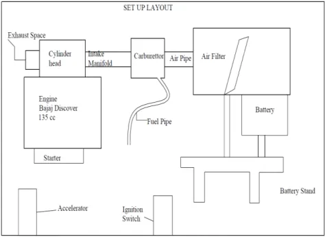
Swirl at the end of compression and beginning of combustion will break into turbulence motion due to upward motion of the piston. Higher level of swirl does not improve the combustion and emission; instead it reduces the volumetric efficiency as swirl created reduces the kinetic energy of the flowing fluid [19]. Figure 1 and 2 shows useful air-fuel mixture ratio and setup description.
The objective of the present work is to reduce the overall emissions by using the different and uniquely designed intake manifolds on a single-cylinder Bajaj Discover 135 cc ® engine. The parameters of interest are the NOx, CO2, HC and CO emissions and a comparative analysis of emission characteristics.
Fig. 2. The line diagram of test engine set up.
2.
Experimental set-up
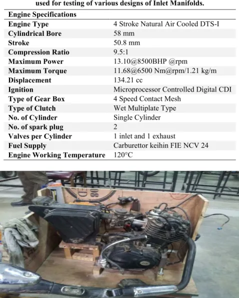
Table 2 gives the specification of test engine is given below in. Table 3 gives the specification of exhaust gas analyser. The engine is tested on the exhaust analyser whose specification is given in Table 2. One end of the intake manifold (Bajaj Discover 135cc) is attached to the carburettor and other end to the combustion chamber shown in Fig. 3.
Table 2. The specifications of the engine used for testing of various designs of Inlet Manifolds.
Engine Specifications
Engine Type 4 Stroke Natural Air Cooled DTS-I
Cylindrical Bore 58 mm
Stroke 50.8 mm
Compression Ratio 9.5:1
Maximum Power 13.10@8500BHP @rpm
Maximum Torque 11.68@6500 Nm@rpm/1.21 kg/m
Displacement 134.21 cc
Ignition Microprocessor Controlled Digital CDI
Type of Gear Box 4 Speed Contact Mesh
Type of Clutch Wet Multiplate Type
No. of Cylinder Single Cylinder
No. of spark plug 2
Valves per Cylinder 1 inlet and 1 exhaust
Fuel Supply Carburettor keihin FIE NCV 24
Engine Working Temperature 120°C
Fig. 3. Actual image of the test engine set up.
Table 3. Specification of exhaust gas analyser.
Gases Measuring Range Measurement Accuracy
Carbon Monoxide [CO] 0-10% ± 0.06% (abs)
Hydrocarbons [HC] 0-9999 ppm ±12 ppm (abs)
Carbon Dioxide [CO2] 0-18% ±0.5%(abs) Oxides of Nitrogen
[NOx]
0-5000 ppm ±0.1%
Oxygen O2 0-25% ±0.5%(abs)
Air Fuel Ratio 0-50 NA
Lambda 0-5 1
Temperature 2°C to 45°C
-40°C to 75°C
At operating Condition At Storage
Table 4. Fuel specifications [20, 21, 22].
Fuel Properties Gasoline
Density (g/cm3), Liquid 0.73
Molar C/H Ratio 0.445
Molecular Weight (kg/kmol) 114.18
Lower Heating Value (MJ/kg) 44
Stoichiometric A/F Ratio 14.6
Auto-Ignition Temperature (K) 501-744
Heat of Vaporisation (KJ/kg) 305
Research Octane Number [RON] 91-100
Research Cetane Number [RCN] -
Laminar Flame Speed (m/s) 0.37
Diffusion Coefficient (cm2/s) 0.05
Experimental methodology
In this experiment, only the intake manifold has been changed subsequently and its effect on the exhaust gases is recorded. The purpose of having four modified pipe was to study the effect on the exhaust gases. Firstly the engine was run with the existing manifold and gases were analysed with using gas analyser of AVL. After this, the designed swirler inlet manifold was installed in the engine and its readings were recorded down. After this the designed venturi type manifold was installed and again new readings were recorded. Comparison was done between these designs according to different gasses as shown in the graphs, the properties of fuel has been shown in table 4.
The reason for changing the inlet manifold design was to produce turbulence in the inlet manifold pipe before it could enter in the engine. Due to this turbulence created before entering the engine, the combustion will be more accurate and due to this better combustion there will be production of less toxic gases. The better atomization of fuel droplets with the air will cause the proper burning.
After following the above steps experimentation has been recorded with the help of analyser as shown in Table 5.
The experiment, for different designs, was performed four times repeatedly with the time interval of five minutes with the help of gas analyser.
The experiment was performed on DTSI 135 cc Digital Twin Spark Ignition Engine, which was manufactured by Bajaj Auto India Limited. Exhaust gas analyser Model No. AVLdigas2200 had been used to analyse the emissions of CO, CO2, HC and NOX. In addition, other instruments like Vernier calliper and surface roughness detector has also been used for the measurement of diameter, length and surface roughness of different inlet manifolds.
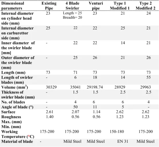
Table 5. Dimensions/properties and cross-sectional view of existing and modified intake manifolds.
Dimensional parameters Existing Pipe 4 Blade Swirler Venturi pipe Type 1 Modified 1 Type 2 Modified 2 Internal diameter
on cylinder head side (mm)
23 Length = 25 Breadth= 20
23 21 24
Internal diameter on carburettor side (mm)
25 22 22 25 21
Inner diameter of the swirler blade [mm]
- 22 22 14 21
Outer diameter of the swirler blade (mm)
- 25 26 21 26
Length (mm) 73 71 73 73 73
Length of swirler blades (mm)
- 6 18 14 55
Volume (mm3) 30329 35041 29198.74 28929 29963
Thickness of swirler blade (mm)
- 1.5 1.5 2.5 2.5
No. of blades - 4 6 6 4
Angle of blade (°) - 50 11 5 -
Surface Roughness Max. (mm) Min. (mm) 2.61 1.40 2.07 0.56 1.14 0.56 2.62 1.23 2.62 1.23 Working
Temperature (°C)
175-200 175-200 175-200 150-180 175-200
3.
Results and Discussions
In this article, the exhaust emissions are considered as a main challenge. In exhaust emissions, The major constituents which contribute to air pollution are carbon monoxide (CO), Oxides of nitrogen (NOx) and hydrocarbons (HC) coming from the S.I Engine Exhaust.
The exhaust emission values which are given in Table 6 are the mean values of the consecutive repetitions of experiment. The standard deviations of the mean values are given in Table 7.
Table 6. Exhaust emission obtained through exhaust gas analyser.
Modifications
CO Emission
(v/v %)
CO2 Emission
(v/v %)
HC Emissions
(ppm)
NOx Emission
(ppm) Existing Inlet
Manifold
1.76 1.9 327 170
4- Blade Swirler 2.26 3.50 254 165
Venturi 0.82 5.36 180 120
Type 1 six blade helical
0.62 2.7 750 155
Type 2 Modified 2 0.82 2.2 147 102
Table 7. Standard deviation in exhaust emission.
Modifications
CO Emission
(v/v %)
CO2 Emission
(v/v %)
HC Emissions
(ppm)
NOx Emission
(ppm) Existing Inlet
Manifold
0.018 0.033 1.825 2.062
4- Blade Swirler 0.009 0.018 1.825 2.380
Venturi 0.020 0.024 4.203 1.707
Type 1 six blade helical
0.012 0.238 1.707 2.629
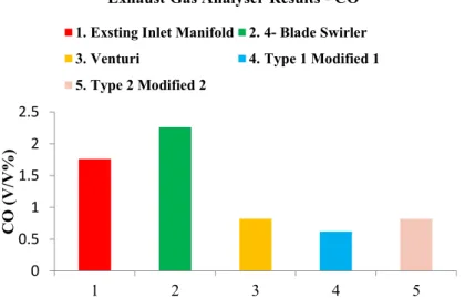
Fig. 4. Comparative analysis of CO emissions between the existing inlet manifold and different modified designs of inlet manifold vis-à-vis the
standard emissions (BS II, 2005).
Carbon Monoxide (CO) figure 4 – In the comparative analysis of existing manifold with different modified designs of inlet manifold. It is observed that the CO reading is higher in existing and 4-blade swirler than the other modified inlet manifolds. It is observed that CO is increased by 22% in 4-blade swirler and decreased by 53%, 65% and 53% in venturi, modified-1 and modified-2 inlet manifold as compared to existing manifold. This is due to proper mixing of fuel which occurs in modified-1 and modified-2 inlet manifold. In modified-1 and manifold, blades are designed to provide a proper path to the mixture to flow which results in the proper mixing of air & fuel. Due to the turbulence, which is taking place inside the manifold; CO emissions are more or less as the standard emissions. In venturi and modified-2 inlet manifold, CO is higher than the modified-1 but still lesser than the existing manifold. It shows that any obstruction in inlet manifold results in better atomization which leads to complete combustion. Here we can conclude that the atomization of fuel is important for reduction of CO emissions. Moreover, provision of turbulence in the intake manifold leads to a better combustion by proper mixing of air-fuel mixture.
0 0.5 1 1.5 2 2.5
1 2 3 4 5
CO
(
V/V%)
Exhaust Gas Analyser Results - CO
1. Exsting Inlet Manifold 2. 4- Blade Swirler
3. Venturi 4. Type 1 Modified 1
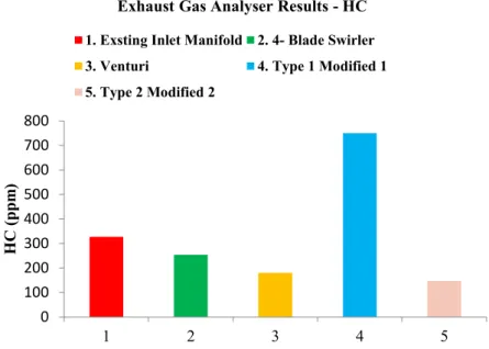
Fig. 5. Comparative analysis of HC emissions between the existing inlet manifold and different modified designs of inlet manifold vis-à-vis the
standard emissions (BS II, 2005).
Hydrocarbons (HC) figure 5 – In the comparative analysis of existing manifold with different modified designs of inlet manifold. It is observed that HC is increased by 56% in modified-1 inlet manifold and decreased by 22%, 81% & 55% in 4-blade swirler, venturi & modified-2 inlet manifold. Design variables are responsible for higher HC emissions in modified- 1 inlet manifold. The design of the blades is made to create turbulence with the high pressure. Due to this design, the mixture is highly pressurized when it leaves the inlet manifold, which causes the deposition of gas particles on the walls of combustion chamber. Later in the cycle when exhaust valve opens the particles get desorbed back into the cylinder & comes out from the exhaust manifold increasing the HC emissions. HC is more in existing manifold than the modified – 2 inlet manifold due to the straight or unobstructed path, provided by the existing manifold, which do not impart the mixing in the flow. It is seen, 4-blade swirler and type-2 modified manifold has the lesser HC emission which is due to the design of induction system. The design of type-2 modified manifold is made only for the proper mixing of air and fuel by means of obstructed path not to compress the mixture. Therefore when the mixture leaves the inlet manifold is at relative pressure which will not cause the deposition on the walls. On the other hand, in venturi there is a tremendous decrement (81%) in HC emission due to the reason of the optimum pressure along with the proper mixing.
0 100 200 300 400 500 600 700 800
1 2 3 4 5
H
C
(pp
m
)
Exhaust Gas Analyser Results - HC
1. Exsting Inlet Manifold 2. 4- Blade Swirler
3. Venturi 4. Type 1 Modified 1
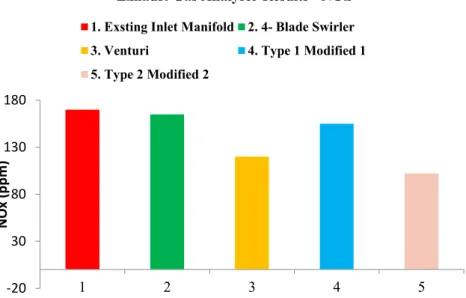
Fig. 6. Comparative analysis of NOx emissions between the existing inlet manifold and different modified designs of inlet manifold vis-à-vis the
standard emissions (BS II, 2005).
Oxides of Nitrogen (NOx) figure 6- In the comparative analysis of existing manifold with different modified designs of inlet manifold. There is 2.9%, 29%, 9% and 40% of NOx reduction was observed in 4-blade swirler, venture, modified-1 and modified-2 inlet manifold as compared to existing manifold. It is seen that, NOx is maximum in existing inlet manifold & minimum in type-2 modified manifold which is almost same as standard. It is noticed, type-2 modified manifold has the minimum NOx emission which is due to the design of induction system. The design of type-2 modified manifold is made only for the proper mixing of air and fuel by means of obstructed path not to compress the NOx mixture. Therefore, the less pressurized mixture will not lead the temperature rise as compared to high pressurized mixture. This is the reason for the higher NOx in 4-blade swirler and modified -1 manifold.
-20 30 80 130 180
1 2 3 4 5
N
Ox (p
p
m
)
Exhaust Gas Analyser Results - NOx
1. Exsting Inlet Manifold 2. 4- Blade Swirler
3. Venturi 4. Type 1 Modified 1
Fig. 7. Comparative analysis of CO2 emissions between the Existing Inlet Manifold and different modified designs of inlet manifold vis-à-vis the
standard emissions (BS II, 2005).
Carbon-dioxide (CO2) figure 7: In the comparative analysis of existing manifold with different modified designs of inlet manifold. It is observed that CO2 is increased by 45%, 65%, 30% and 13% in 4-blade swirler, venturi, modified-1 and modified-2 inlet manifold. This is clear that the engine is operating more efficiently with the modified designs rather than existing one. Here, Carbon from the fuel is fully oxidized due to the proper mixing of fuel and air in these designs.
4.
Conclusions
The research had aimed for the reduction of vehicular pollutant levels by the application of economical, indigenous and eco-friendly designs. It was thought of, that by varying structural design parameters and by introducing certain obstructions to the path of air-fuel mixture, an increased swirl could be created in the intake manifolds of the test Spark Ignition Engine. Moreover, the applicability of these designs had been firmly tested by the use of reliable exhaust gas analysers and an appropriate analysis was henceforth done. Based on the test, some of the concluding results are presented below.
It is evident that the 2.9% and 22% reduction in the NOx and unburnt hydrocarbons respectively but 22% increase in CO emissions was a result of 4-blade swirler based inlet manifold. It can also be noted that 53%, 29% and 81% reduction in the CO, Nox and unburnt hydrocarbons respectively was a result of the Venturi based inlet manifold.
0 1 2 3 4 5 6
1 2 3 4 5
CO
2
(
V/V%)
Exhaust Gas Analyser Results - CO2
1. Exsting Inlet Manifold 2. 4- Blade Swirler
3. Venturi 4. Type 1 Modified 1
In Modified-2 inlet manifold, a 53%, 40% and 55% reduction in the CO, Nox and unburnt hydrocarbons respectively was achieved whereas Modified -1 inlet manifold exhibited a reduction in CO and NOx by 65% and 9% respectively but an increase in the unburnt hydrocarbons by 56%. It was concluded that the Modified 2 inlet manifold had an advantage over the existing inlet manifold.
The summated results concluded that the Venturi based inlet manifold and Modified – 2 based inlet manifold ensured an efficient combustion, optimum pressure and emissions due to which there were significant reductions in the amount of CO, NOx and unburnt hydrocarbons. Hence it can be concluded that out of four different designs which were tested, the Venturi based inlet manifold and Modified-2 inlet manifold have shown exceptionally good results.
As environmental issues, acid rain due to NOx, global climate change due to greenhouse gases, crop and forest damage due to overall air pollution are also taken care by reducing the emissions with the help of modified designs of inlet manifold. As the greenhouse gases reduced in suggested modified intake manifold. Therefore uneven melting of glacier, sea level Will reduce by applying suggested model in existing two wheeler Bikes. The results can be an excellent platform for further research and more solutions to the ongoing issue can be solved through conclusive engineering exploration into this extensive field.
References
1. Zhang, Y.; Stedman, D. H.; Bishop, G.A.; Guenther, P.L.; and Beaton, S.P. (1995). Worldwide on-road vehicle exhaust emissions study by remote sensing. Environmental science & technology, 29(9), 2286-2294.
2. Kathuria, V. (2004). Impact of CNG on vehicular pollution in Delhi: a note.
Transportation research part D: Transport and environment, 9(5), 409-417. 3. Schwela, D.; Zali, O.; and Schwela. P. (1997). Motor vehicle air
pollution-Public health impact and control masures. World Health Organization and ECOTOX, 10-34.
4. Gorse Jr.; and R.A. (1992). The effects of methanol/gasoline blends on automobile emissions. SAE Paper 920327,doi:10.4271/920327.
5. Salih, F.M.; Andrews, G.E. (1992). The influence of gasoline/ ethanol blends on emissions and fuel economy. SAE fuel and lubricants meeting SAE Paper
922378,doi:10.4271/922378.
6. Chandler, K.; Whalen, M.; and Westhoven, J. (1998). Final result from the state of Ohio ethanol-fueled light-duty fleet deployment project, SAE Paper
982531, doi:10.4271/982531.
7. Feychting, M.; Svensson, D.; and Ahlbom, A. (1998). Exposure to motor vehicle exhaust and childhood cancer. Scandinavian journal of work, environment & health, 24(1), 8-11.
9. Amatayakul
, W.; and O.J. Ramnos. (2001). Life cycle assessment of a
catalytic converter for passenger car.
Journal of cleaner production, 9(5),395–403.
10. Moldovan, M.; Gómez-Gómez, M.; and Palacios-Corvillo, M. A. (2006). Release of particulate and acid soluble palladium from catalytic converters into the environment. In Palladium emissions in the environment Springer
Berlin Heidelberg, 25-38).
11. Tyagi, R. K.; and Ranjan, R. (2013). Effect of hydrogen and gasoline fuel blend on the performance of SI engine. Journal of petroleum technology and alternative fuels, 4(7), 125-130.
12. Ilyas, S.Z.; and Zafar. S. (2007). A Review of transport and urban air pollution in Pakistan. Journal of applied sciences and environmental management, 11( 2), 113–121.
13. Keegan, D.A. (2009). Air swirling device for fuel injected internal combustion engines .Patent application No- US 12/454,846
14. Jemni, M. A., Driss, Z., Kantchev, G., & Abid, M. S. (2013). Intake manifold shape influence on the unsteady in-cylinder flow: Application on LPG Bi-fuel Engine. In design and modelling of mechanical systems, Springer Berlin Heidelberg, 331-338).
15. Breisacher, P., Nichols, R. J., & Hicks, W. A. (1972). Exhaust emission reduction through two-stage combustion. Combustion science and technology, 6(4), 191-201.
16. Mohammad Amin, M. (2010). Intake and exhaust ports flow investigation of 4-stroke SI engine (Doctoral dissertation, University Malaysia Pahang). 17. Sulaiman, S. A.; Murad, S. H. M.; Ibrahim, I.; and Abdul Karim, Z. A.
(2010). Study of flow in air-intake system for a single-cylinder Go-Kart engine. International journal of automotive and mechanical engineering (IJAME), 1(1), 91-104.
18. Ganesan, V. (1996). Internal combustion engines (4th ed). McGraw-Hill. 19. Fontana, G.; Galloni, E.; Jannelli, E; and Palmaccio, R. (2003) Influence of
the intake system design on a small spark-ignition engine performance: A theoretical analysis. SAE Paper No1-3134-3135.doi:10.4271/922378. 20. Kosar, M.;, Ozdalyan, B.; & Celik, M. B. (2011). The usage of hydrogen for
improving emissions and fuel consumption in a small gasoline engine. Isi Bilimi ve Teknigi Dergisi/Journal of thermal science & technology, 31(2), 25-32.
21. Tyagi, R. K..; and Ranjan, R. (2013). Effect of heating the catalytic converter on emission characteristic of gasoline automotive vehicles. International journal of ambient energy, l. 34,doi:10,1090/01430750.2013.853205.


![Table 4. Fuel specifications [20, 21, 22].](https://thumb-eu.123doks.com/thumbv2/123dok_br/18296169.347159/7.892.130.607.108.248/table-fuel-specifications.webp)