Fusion of Multi-Scale Visible and Thermal
Images using EMD for Improved Face
Recognition
Vaidehi. V
1, Ramya. R
2, PrasannaDevi. M
2,
Naresh Babu N T
2, Balamurali P
3, Girish Chandra M
3Abstract- This paper presents the implementation of face recognition system using JDL framework. Fusion of visible and thermal images enhances the recognition rate and efficiency under varying illumination conditions. In this system, registration of visible and thermal images is performed using Fourier based method and fusion is performed using Empirical Mode Decomposition (EMD). The feature extraction and face recognition is implemented with Block Independent Component Analysis (BICA) using K-NN classifier. It is found that the proposed system out performs the existing face recognition system using single sensor.
Index Terms - Empirical Mode Decomposition, Intrinsic Mode Function, Image fusion, Image registration.
I. INTRODUCTION
Visible images are the face images obtained in the visible spectrum and vary according to the illumination conditions. Visible image holds the details of the necessary features of the face images, required in the process of biometric authentication [4]. Since visible images vary according to the luminance and conditions under which the test images are taken, they are viable to result in error or otherwise wrong recognition.
Thermal face images are captured using an IR sensor
camera in the far IR region (8μm -12μm). Thermal Image
gives the measure of energy radiations from the object and it is less sensitive to illumination changes and is even operable in darkness. The energy radiated from the face, may change according to the surroundings and due to the physical exertions. The features of the face, the primary requisite for acquiring the correlation with the database images are indistinguishable in case of thermal image. In addition, thermal image as a standalone does not provide high-resolution data [4]. Hence, fusion of visible and thermal images provides better solution to achieve the best feature of both the images for Face recognition system [8]. Hence this paper proposes a novel scheme of fusion visible and thermal images and a Face Recognition system (FRS) integrating registration and fusion of face images.
Manuscript submitted January2011. This work is supported by Tata Consultancy Service (TCS), Bangalore, INDIA.
1 Head of the Department of Information Technology, MIT, Anna
University, Chennai, India ([email protected]).
2 Department of Electronics Engineering, MIT, Anna University,
Chennai, India ([email protected])
3 Innovations lab, TCS Bangalore, India
In the proposed system image registration is done on the edges of visible and thermal images before fusion. This increases the performance compared to other methods proposed in the literature survey [4, 8]. The fused images are used as input images to the face recognition module, thereby reducing the need to store separate databases for visible and thermal images.
The rest of the paper is organized as follows: Section II describes the Fourier based registration method. Section III explains the process of Empirical mode Decomposition. Section IV deals with the JDL framework of validation of fused images for face recognition using Block Independent Component Analysis with K-NN classifier. Section V discusses the results for registration and fusion of thermal and visible images.
II. REGISTRATIONOF IMAGES
Image registration [3] is the process of overlaying two or more images of the same scene taken at different times, from different viewpoints, and/or by different sensors. It geometrically aligns two images—the Visible Image and Thermal Image. The present differences between images are introduced due to different imaging conditions. Image registration is a crucial step in all image analysis tasks in which the final information is gained from the combination of various data sources like in image fusion, change detection, and multi-channel image restoration. Software registration of images replaces a special-purpose imaging sensor assembly and produces co-registered image pairs [10]. The co-registered images provide us both the information of the visible as well as the thermal images.
Registration algorithms typically assume that images differ by some transformation. Transformation include rigid transforms (translation, rotation, and rescaling), linear and affine (skewed and perspective transforms), and nonlinear warping.
A. Image Fusion
higher abstraction suppresses inconsistencies, artifacts and noise in the fused images.
In this paper, the Empirical Mode Decomposition (EMD) based image fusion technique is used wherein image decomposition is performed on input images. The visible and thermal images are fused at decomposition level. A weighting scheme is used to minimize the mutual information and to enrich the information from the input images based on the illumination content. Visible and thermal IR sensors capture complementary information of reflectance and radiation from the face [4]. A pair of visible and thermal IR face images must be spatially registered before any useful information is extracted from the fused images [8].
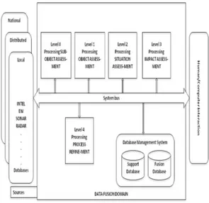
Fig 1. JDL framework for FRS
B. JDL framework for Face Recognition System
Fig 1. gives the overall flow diagram of JDL framework. There are five levels in the JDL Framework which have been adapted for the fusion framework as follows.
Level 0 − Sub-Object Data Assessment: In this all the pre processing of the input image is performed. This includes resizing the image and detect the edges using Canny based edge detection.
Level 1 − Object Assessment: Estimation and prediction of the relations among the thermal and visible image and registration is performed in this level.
Level 2 − Situation Assessment: The visible and thermal images are decomposed using Empirical Mode Decomposition.
Level 3 − Impact Assessment: The fusion of the visible and thermal images in their decomposed form is performed. Suitable weights are used to decrease the mutual information.
Level 4 − Process Refinement: The face recognition is done using Block Independent component analysis with K-
NN classifier. The performance of the fused images is compared with that of the visible image.
C. Image Registration
In order to proceed with the process of registration, the images are transformed based on the transformations as stated below.
Transformations
Frequency-domain methods find the transformation parameters for registration of the images while working in the transform domain (linear transformation). Such methods work for simple transformations, such as translation, rotation, and scaling.
Applying the Phase correlation method to a pair of images produces a third image which contains a single peak. The location of this peak corresponds to the relative translation between the images. Unlike many spatial-domain algorithms, the phase correlation method is resilient to noise, occlusions, and other defects. The phase correlation uses the Fast Fourier transform to compute the cross-correlation between the two images.
Affine Transformation
In many imaging systems, detected images are subject to geometric distortion introduced by perspective irregularities. Applying an affine transformation to a uniformly distorted image can correct for a range of perspective distortions by transforming the measurements from the ideal coordinates to those actually used. The general affine transformation is commonly written in homogeneous coordinates as shown below:
2 1
2 1
*
x x
A B
y y
The order in which the transformations occur is significant since a translation followed by a rotation is not necessarily equivalent to the converse. Geometrically, an affine transformation in Euclidean space is one that preserves the collinearity relation between points; i.e., three points which lie on a line continue to be collinear after the transformation. Also the ratio of distances along a line with distinct collinear points p1, p2, p3, is constant as given below:
2 1
3 2 p p
k p p
The various steps that have been followed for registration of the multi-sensor images are presented below.
Edge detection
Log-polar transformation
The log-polar transformation is a conformal mapping from the points on the Cartesian plane (x,y) to points in the
log-polar plane (x,
). When compared to the usualCartesian images, the log-polar images allow faster sampling rates on artificial vision systems. The mapping is described by:
2 2
log( (
x x y ;
arctan( / )
y x
This is obtained by reducing the resolution at the image periphery, thus high resolution improves the performance.
Phase correlation function
Fourier transform is used to decompose an image into its sine and cosine components. In the Fourier domain image, each point represents a particular frequency contained in the spatial domain image. For an image of size N×N, the two-dimensional DFT is given by:
( )
2 ,
1
( , )
( , )
ka ib N a b
F k l
f a b e
N
For the registration of the visible and thermal images, the scaling factor and the angle of rotation with respect to one image is found. The two Fourier transforms are then multiplied using the given formula to get the phase correlation matrix. If f and g are two images, then F and G are their Fourier transforms. The cross-power spectrum (phase correlation) is FG*/|FG*| where * is the conjugate of the image.
( ( , )) ( , ) *
( ( , ) * ( , )
conj G x y PCM F x y
mag F x y G x y
Rotation and scaling parameter
The inverse Fourier transform of the phase correlation function is taken. The location of the peak value is taken into consideration for finding the rotation angle and scaling parameter. If(x,y) is the location of the peak of the inverse Fourier transform of the cross-power spectrum phase, then
( )
10
x imagewidth
Scale
3 6 0 *
a n g le y
im a g eh eig h t
These values are then used to rotate and scale the visible image.
III. EMPIRICAL MODE DECOMPOSITION
EMD is an adaptive decomposition method with which any complicated signal can be decomposed into its Intrinsic Mode Functions (IMF). An IMF is an indicative of intrinsic oscillatory modes in a complex signal, with
specific properties which are (1) the number of extrema and the number of zero crossings in the IMF signal must either equal or differ at most by one; and, (2) at any point, the mean value of the maxima envelope and the minima envelope is zero.
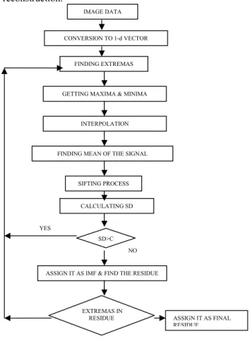
With IMFs, short time changes in frequencies can be described, which cannot be resolved by Fourier spectral analysis. EMD was originally proposed for time-frequency analysis for non-stationary signals. In EMD process, any complicated signal can be decomposed into a redundant set of IMFs and a residue. By adding all of the IMFs along with the residue, the original signal can be recovered with less distortion. The process of EMD for images is given as flowchart in Fig.2.
A. EMD Assumptions
EMD is a data-driven and an intuitive process with the basis functions based on and derived from the data. The assumptions for this method are
1. The signal has at least a pair of extrema,
2. The characteristic time scale is defined by the
time between the successive extrema.
If there are no extrema, and only inflection points, then the signal can be differentiated to realize the extrema, then IMFs can be extracted. Integration may be employed for reconstruction.
Fig. 2. Flow chart of EMD for images
CALCULATING SD
ASSIGN IT AS IMF & FIND THE RESIDUE SD>C
YES
EXTREMAS IN
RESIDUE ASSIGN IT AS FINAL RESIDUE NO
IMAGE DATA
CONVERSION TO 1-d VECTOR
FINDING EXTREMAS
GETTING MAXIMA & MINIMA
INTERPOLATION
FINDING MEAN OF THE SIGNAL
B. Sifting Process
Considering X(t) is a complex signal, which has to be
decomposed and it is assigned as r0. The extrema points of
the signal are found. The upper and lower envelopes are formed using cubic spline interpolation from the local maxima and minima points respectively. The point wise mean of upper and lower envelopes is found which is designated as m1. For the first iteration, h1 is obtained as
0 ( )
r X t (1) X t( )m1h1 (2)
For the next iteration, h1 is treated as input and sifted value is found as
11 1 11
h h m (3)
The sifting is continued k times till the first IMF, is obtained.
( 1)
lk l k lk
h
h
m
(4)c1 is designated as the first IMF,
1 l k
c h (5)
C. Stopping Criteria
In sifting process, the number of sifting i.e. k is decided by stopping criteria, which measures the standard deviation between the present and previous iterations.
2 ( 1)
2 ( 1)
i k ik
i k
h h
SD
h
(6)Sifting is stopped if SD falls below a threshold. The
isolated IMF, c1 contains the finest scale of the signal and
c1 is separated from the data.
r
1
r
0
c
1 (7)The residue r1 still holds lower frequency information. For
the next sifting, r1 is considered as input. It is repeated till a residue with no extrema points is obtained.
r
1
c
2r
2,..,
r
n1
c
nr
n (8)The input signal can be reconstructed by adding all IMFs and the final residue.
1
'( )
n i n i
X t c r
(9)D. EMD for Images
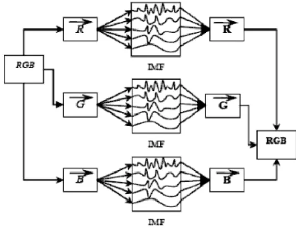
The EMD was originally proposed for 1-D time signals. It can be used for images by converting 2-D image data to 1-D vectors. The conversion is accompanied by ‘lexicographical rearrangement’. Then this 1-D vector can be decomposed using EMD. The 1-D IMF signals can be converted to 2-D images by rearranging the vector elements. Also the EMD can be extended for color images. Any color image will have three 2-D matrices for red, green, and blue components. The RGB components are separated and each component is decomposed using EMD. Fig 3 represents the IMFs of the RBG components of the image which then fused into a single image by reconstruction.
IV.VISIBLE-THERMAL IMAGE FUSION
Face recognition based on the visible spectrum is difficult in out door applications. The accuracy of face recognition degrades quickly with illumination conditions.
Thermal IR spectrum (3-12 μm) has been suggested as an
alternative source of information for face detection and recognition. Thermal IR sensors measure the emitted heat energy, not reflected, from the object. Hence thermal imaging has great advantages in face recognition in low illumination conditions or even in darkness. The combination of multi-modal images significantly improves the performance of face recognition in uncontrolled operating environments. The basic steps for fusion of visible and thermal images are explained as follows.
1. A pair of visible and thermal color images of same face
captured in same view is taken. The images are obtained as 3-D data.
2. The RGB components in the both the images are separated. Three pairs of 2-D data are decomposed separately using EMD.
3. The 2-D matrices are converted into 1-D vector using lexicographical rearrangement.
4. The local maxima and local minima of the data are found and two envelopes viz. upper and lower are found respectively by cubic spline interpolation. 5. The mean between the envelopes are found and then
preceded with sifting process to find all the IMFs using EMD as described above for all the six vectors.
6. For fusion of images, these IMFs of RGB components
of two different modalities are added as
( , , )
1
( , )
k
R G B j j j j
j
F X Y V T
(10)where F(x,y) is the fused image of individual components, j & j are weighting factors for visible & thermal IMFs, Vj is the jth visible IMF,Tj is the jth thermal IMF and k is the number of IMFs.
Here weighting factors are used to decrease the mutual information between visible and thermal [1].
Visible image Thermal image
Registered image Aligned images
V. IMPLEMENTATION RESULTS
A. Registration
The basic scheme of the proposed implementation is shown in Fig. 4, describing the scheme of fusion of the visible and thermal images. In this proposed face recognition scheme the input images are checked for their alignment before fusion. If they are not aligned, the spatially aligned using software based image registration and fused using EMD. A misaligned visible and thermal image pair is taken and aligned using Fourier based technique. Such pair of misaligned image pair and the results of registration is shown in Fig 5.
Fig. 4. Basic scheme of fusion with registration
Fig.5. Registration of images
B. Fusion of images
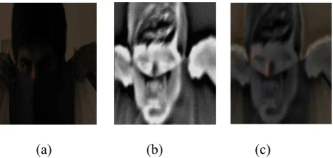
The method of decomposing an image using EMD is implemented using VC++ using OpenCV library. The fusion is performed at decomposition level. The input images are resized to decrease the time of processing. The RGB components are separated and converted to 1-D vectors. The vectors are decomposed individually. The IMFs are added with weighting factors. The vectors are converted back to 2-D data and RGB components are combined. In Fig.6, a masked face image captured in a low illumination condition is used. From the visible image, the information about the colors and eye are extracted and
from the thermal image information about the outline of face is extracted. The information are integrated in the fused image. The fused image by averaging method is shown for comparison. Fig.7 gives the result obtained after fusion of the registered images using OpenCV in Visual C++.
(a) (b) (c)
Fig.6. Fusion of images (a) Visible Image (b) Thermal Image (c)Fused image using EMD
Fig.7. Image registration and Fusion.
C. Classification of fused images using BICA
Block Independent Component Analysis (BICA) is a computational method for separating a multivariate signal into additive subcomponents supposing the mutual statistical independence of the feature components. Fig.8 shows the result for classification of the fused input image using BICA with K-NN.
Figure 9 shows the graph obtained by comparing the False Rejection Ratio(FRR) of face recognition of the visible image under dark condition and the fused image separately. It can be seen that the performance is better when fused images are used.JDL framework for fusion is the generic method of fusion. The various levels of the FRS are acquisition of the visible and thermal images, Fourier based registration, EMD based fusion and its
Image registration Visible image
Thermal image
EMD based fusion
Visible face recognition
validation using BICA with K-NN classifier. These stages of FRS substantiate to those of the JDL framework.
Fig.8. Classification of the fused input image using BICA with K-NN.
Fig.9.Comparision graph of FRR by using fused image of visible image thermal image, and by using only visible image.
VI. CONCLUSION
This paper presented a JDL fusion framework for Face recognition system. The system used Fourier based registration, EMD fusion of thermal and visible images, BICA based feature extraction and K-NN based classification. The performance of the fusion based Face Recognition System is found to be better than single sensor based FRS. As this system proposes a scheme in which edges are detected before registration.
REFERENCES
[1] Dr Ardy Goshtasby ,Various multi-exposure and multi-focus images (provided from Image Fusion Systems Research), www.imagefusion.org.
[2] Anna Linderhead, “Adaptive image compression with wavelet packets and empirical decomposition” -a thesis submitted to Department of Electrical Engineering, Linkoping University, Sweden.
[3] L.G.Brown, Dec 92,A survey of image registration techniques-ACM computing surveys, Vol 24 No 4 PP 325-376.
[4] David Looney and Danilo, P. Mandic, APRIL 2009 Multiscale Image Fusion Using Complex Extensions of EMD, IEEE Transactions on Signal Processing , Vol. 57, No. 4.
[5] Dong Zheng, Jiying Zhao, and Abdulmotaleb El Saddik, RST-Invariant Digital Image Watermarking Based on Log-Polar Mapping and Phase Correlation.
[6] Gary Bradski and Adrian Kaehler“ Learning Open CV” 1st Edition,
O’Reily Publications,2008.
[7] R.Gonzalez and R.Woods, Digital Image Processing, 3rd Edition,
Prentice Hall Publications, 2007.
[8] H. Hariharan, A. Koschan, B. Abidi, A. Gribok, and M.A. Abidi, , October 2006, "Fusion of visible and infrared images using empirical mode decomposition to improve face recognition," in Proc. IEEE Trans. on Image Processing ICIP2006, Atlanta, GA, pp. 2049-2052.
[9] S. G. Kong, J. Heo, F. Boughorbel, Y. Zheng, B. R. Abidi, A. Koschan, M. Yi, and M. A. Abidi, Feb. 2007, "Multiscale Fusion of Visible and Thermal IR Images for Illumination-Invariant Face Recognition," International Journal of Computer Vision, Special Issue on Object Tracking and Classification Beyond the Visible Spectrum, Vol. 71, No. 2, pp. 215-233.