Francisco Carlos P. Bizarria* Institute of Aeronautics and Space São José dos Campos-Brazil fcpb@iae.cta.br
Silvana Aparecida Barbosa Institute of Aeronautics and Space São José dos Campos-Brazil silvana@iae.cta.br
José Walter P. Bizarria University of Taubaté Taubaté- Brazil jwpbiz@gmail.com
João Maurício Rosário State University of Campinas Campinas-Brazil rosario@fem.unicamp.br
*author for correspondence
Evaluation of the impact of
convolution masks on algorithm
to supervise scenery changes at
space vehicle integration pads
Abstract: The Satellite Launch Vehicle developed in Brazil employs a specialized unit at the launch center known as the Movable Integration Tower. On that tower, ixed and movable work loors are installed for use by specialists, at predeined periods of time, to carry out tests mainly related to the pre-launch phase of that vehicle. Outside of those periods it is necessary to detect unexpected movements of platforms and unauthorized people on the site. Within that context, this work presents an evaluation of different resolutions of convolution mask and tolerances in the eficiency of a proposed algorithm to supervise scenery changes on these work loors. The results obtained from this evaluation are satisfactory and show that the proposed algorithm is suitable for the purpose for which it is intended.
Keywords: Scenery supervision, Convolution mask, Digital image processing, Satellite Launch Vehicle.
INTRODUCTION
Nowadays, Satellite Launch Vehicles (SLV), developed in Brazil, require their parts to be integrated at specialized facilities at the launch center to allow tests to be carried out, mainly related to the pre-launch phase of the vehicle (Palmério, 2002). For the purposes of this integration, a specialized unit at the launch center called the Movable Integration Tower (MTI) is used.
This tower is supported by a rectangular box-shaped metal structure - the longest side of which is vertical - equipped with a rail-mounted horizontal movement subsystem.
There are planned strategic points on that structure for the installation of an overhead traveling bridge, an
elevator, work platforms (ixed and movable), doors and
other subsystems necessary to cope with the activities undertaken on the tower (Yamanaka, 2006).
The ixed and movable loors are installed at preset levels
on the interior of the integration tower, which houses several pieces of equipment used to carry out the activities related to the integration and testing of subsystems embedded in the aforementioned vehicle.
The activities undertaken at those loor levels are
performed by specialists who need to adhere to a sequence of preset activities at predetermined periods of time.
Outside of those periods of time it is necessary to detect unexpected movements of the movable platforms, the presence of unauthorized people or elements not related to the site where those activities are being carried out.
Within this context, the current work presents an evaluation of different resolutions of convolution mask and tolerances
relating to the eficiency of a proposed algorithm to supervise changes in a predeined environment on those work loors.
The main goal of this work is to present the results obtained from the use of different convolution mask resolutions on
the eficiency of the algorithm that performs successive comparisons of images, treated by the average ilter
method, to detect scenery changes at the pad dedicated to the integration of satellite launch vehicles.
METHODOLOGY
System Architecture
To evaluate the impact of the use of different resolutions
of convolution mask on the eficiency of the algorithm
presented in this work, a prototype was built which adopted the architecture shown in Fig. 1.
It may be observed in Fig. 1, that the prototype architecture is split into three main parts:
i) Tower Model with Fixed Floor, Movable Floor and Lighting.
Received: 04/05/09 Accepted: 29/10/09
Figure 1. Architecture adopted to evaluate the eficiency of
algorithm.
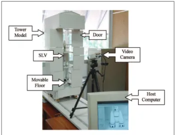
Figure 2. Prototype view.
ii) Video Camera.
iii) Host Computer with Digital Frame Grabber Board and Application Software to detect scenery changes.
The application software was developed to perform all phases foreseen in the algorithm presented in this work, including the display resources for the operators relating to the system of images used as reference in the comparisons and the images captured in continuous mode by the camera and frame grabber unit.
Prototype
A view of the components devised for the prototype to evaluate the use of different resolutions of convolution
mask in the eficiency of the algorithm to detect changes
of scenery at pads employed in the integration of satellite launch vehicles is presented in Fig. 2.
We chose one of the internal spaces, which are deined by the levels where the ixed and movable loors are located
on the Tower Model, to evaluate the impact of the use of
different resolutions of convolution mask on the eficiency
of the algorithm to detect scenery changes.
Based on this, the Direct Lighting System was installed to illuminate the chosen space uniformly and to provide the Video Camera with proper operating conditions.
The positioning of the Video Camera optical system was chosen to provide the very best observation of the Movable Floors, in addition to the pads that are installed in close proximity to the Satellite Launch Vehicle body and are also used for physical access when the operators carry out their tasks on the vehicle.
Outside the period when the tasks are being undertaken, the
occurrence of unexpected movement of these loors and/or
the presence of unauthorized people and/or elements not
related to the site are situations that should be identiied
immediately by the operation’s security team.
Starting with this identiication, the security team should
take every appropriate action aimed at either resolving the situations or minimizing their consequences.
The purpose of the Host Computer is to receive the Digital Frame Grabber Board and the Application Software that is able to detect the scenery changes.
The analog video signal created by the camera is received by the frame grabber board, which transforms it into a digital matrix based on the detected image.
In this igure it can be identiied: the Movable Integration
Tower, the Video Camera with a three-legged support and the Host Computer, which were used in the carrying out the practical tests of this work.
The Movable Integration Tower representational model was developed on a scale of about one to thirty-three
and consists of ive levels for the doors, ive levels for the loors, stairs and a rail-mounted horizontal movement
subsystem.
Inside the tower there is a representational model of the Satellite Launch Vehicle.
This set-up, comprising the tower and the vehicle, represents
the minimum requirement to relect the real environment
where it might be expected to detect changes of scenery.
The Host Computer is an IA-32 model (Intel Architecture – 32 bits), Intel Pentium IV Processor, 2.8GHz frequency, 1GByte of RAM, running Microsoft® Windows XP
operating system.
A Digital Frame Grabber Board and Application Software to detect scenery changes are installed on the host computer.
The frame grabber board used in the tests is manufactured by National Instruments®, namely the PCI-1405 model
(NI Vision, 2007).
The Application Software that runs the algorithm presented in this work was developed in the integrated development environment of National Instruments®, LabVIEW 7.1
with the IMAQ Vision module (Klinger, 2003).
Algorithm
Using the prototype developed for this work, we discovered that when two successive images from the same scene are captured, with no apparent change detectable by a human observer, an immediate comparison of the respective levels of gray between each pixel making up these images, led to several different results.
These differences mainly related to:
i) Variations in scene lighting.
ii) Accuracy of the camera’s optical and electronic system.
iii) Accuracy of the image acquisition board.
iv) Relative movement between the supervised site and the camera.
v) Variations in the transmission medium of the supervised image.
In order to perform the detection of scenery changes, at a satellite launch vehicle integration pad, this work suggests using an algorithm that minimizes the difference in comparison of gray levels between pixels,
by the application of a digital ilter on those images. The
algorithm, basically, performs, the followings steps:
1st Step: To establish the value of:
i) Tolerance that will be used in the comparison between gray levels of the pixels contained in the image matrix obtained from the supervised scenery with their equivalents in the standard image.
ii) Tolerance in percentage that must be used in the comparison between the number of valid pixels of the image from the supervised scenery and the total number of pixels from the standard image used as reference in the comparisons of the system.
iii) Mask resolution that will be applied in the convolution operations.
2nd Step: To begin the continuous capture of images from the supervised scene using the Digital Frame Grabber Board.
3rd Step: To choose and capture an image from the scene that is related to the desired condition for the supervised site.
4th Step: Does it apply convolution to the captured image
with the spatial average ilter?
If “yes”, to apply the mentioned ilter and perform the
following step (5th Step).
If “no”, only to perform the following step (5th Step).
5th Step: To memorize this captured image to be used as a standard in future comparisons undertaken by the scenery change detection system.
6th Step: To restart the continuous capture of images from the supervised scenery.
7th Step: To perform the same processing applied to the standard image on the images that will be used for comparison.
8th Step: To compare successively, with tolerances, all pixels included in the matrix obtained from the scene with their equivalents from the standard image. For each comparison that presents a pixel value within that tolerance, to increase the accumulator number one (Acc1).
9th Step: To determine the value of accumulator number two (Acc2) from the division between the value obtained in accumulator number one (Acc1) by the quantity of pixels from the image matrix used by the system.
11st Step: Does the comparison of images stop?
If “no”, to perform the sixth step (6th Step).
If “yes”, to perform the next step.
12nd Step: Does it inalize the Application Software?
If “no”, to perform the second step (2ndStep).
If “yes”, to end the Application Software.
The analytical lowchart representing the steps foreseen in
the algorithm to detect scenery changes is shown in Fig. 3.
To render eficiently the system adopted in image
comparison by the algorithm that detects scenery changes, within this application software, it was necessary to process the standard image and the image captured from the supervised scene.
This treatment is represented in the fourth step (4th Step) of
the proposed algorithm, the aim of which is to minimize the previously mentioned variations caused by the lighting, video camera, digital frame grabber board and other interference present at the test environment.
In this context, several kinds of spatial ilters were tested,
however the best results obtained, in the case studied for
this work, was using spatial convolution by average ilter
(Gonzales, 1992).
The resolution of that average ilter impacts on the system
performance in detecting scenery changes, which means, depending on the kind of mask used and tolerance adopted, the algorithm itself becomes more or less accurate in its
identiications.
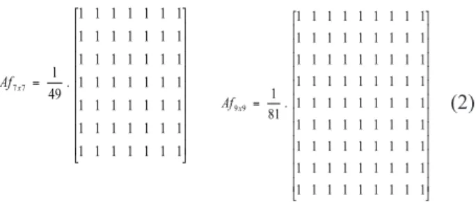
Using the Application Software presented in this work, it
is possible to implement an average ilter with masks of coeficients equal to one (1) and resolution: i) three by three (3x3 matrix), ii) ive by ive (5x5 matrix), iii) seven
by seven (7x7 mask) and iv) nine by nine (9x9 matrix) (Barbosa, 2008).
Eq. (1) presents the masks: i) three by three (Af 3x3) with
standardization factor nine (9) and ii) ive by ive (Af 5x5)
with standardization factor twenty-ive (25).
(1)
Eq. (2) presents the masks: i) seven by seven (Af 7x7) with standardization factor forty-nine (49) and ii) nine by nine (Af 9x9) with standardization factor eighty-one (81).
(2)
Practical Tests
During the implementation of the practical tests performed to validate the use of different resolutions of convolution
mask and tolerances in the eficiency of the proposed
algorithm to detect scenery changes at satellite launch vehicle integration pads, the prototype presented in Fig. 2 was used with the installation of Application Software that
corresponds to the analytical lowchart shown in Fig. 3.
In this context, what is presented is one of the sequences used
in executing those tests. The sequence starts with the deinition
of the following values that are used by the algorithm to detect scenery changes, which means, parameterization of values for use of the application software:
i) Tolerance used in the comparison between levels of gray: 4 (four).
ii) Percentage of tolerance used in the comparison
between valid pixels: 95 (ninety-ive).
iii) Resolution of the convolution mask: 5x5 (5x5 Matrix).
The next action in that sequence relates to the capture and treatment of images that will be used as a standard to perform the comparisons.
Fig. 4 shows part of the main screen of the application software, with the indication of the window that is dedicated to receive the adopted image as a standard in the comparisons that the system will perform. It should be mentioned that the
standard image is subjected to the average ilter.
After deining the values for the parameters of comparison
and of the standard image, it is possible to start the detection of scenery changes by using the continuous capture of images.
Fig. 5 presents an example of an image considered equal to the image adopted as standard (Fig. 4) by the algorithm for the detection of scenery changes.
Fig. 6 shows an example of an image captured by the system which when compared to the image adopted as standard (Fig. 4) indicates a difference due to the algorithm implemented.
Figure 3. Flowchart for detection of scenery changes.
Figure 4. Image adopted as standard.
Figure 5. Image considered equal to the standard.
Figure 6. Image indicating a person on the elevated loor.
Figure 7. Image with indication of movement of the elevated
loor.
The igure also shows in a speciic window, the pixels
from a captured image that are considered different when compared to the corresponding pixels from the image adopted as standard (Fig. 4).
Other tests were carried out to evaluate the impact of the use of different resolutions of convolution mask and tolerances
on the eficiency of the algorithm that detects scenery
changes at Satellite Launch vehicle integration pads.
Fig. 8 shows the results of those comparisons considering that the scenery was not changed, adopting a resolution for image processing of 640 by 480 pixels and mask 3 by 3.
Fig. 10 shows the results of the comparisons for the same conditions as in Fig. 8, except that the mask used is 7 by 7.
Figure 8. Results obtained in comparison of equal images with mask 3x3.
Figure 9. Results obtained in comparison of equal images with mask 5x5.
Fig. 9 shows the results of the comparisons for the same conditions as in Fig. 8, except that the mask used is 5 by 5.
Figure 10. Results obtained in comparison of equal images with mask 7x7.
Figure 11. Results obtained in comparison of equal images with mask 9x9.
Fig. 11 shows the results of the comparisons for the same conditions as in Fig. 8, except that the mask used is 9 by 9.
Fig. 12 shows the results of those comparisons considering that the scenery was changed, adopting an image processing resolution of 640 by 480 pixels and mask 3 by 3. It means that the standard image is compared to another image that reveals the changed position of one of
Fig. 13 shows the results of the comparisons for the same conditions as in Fig. 12, except that the mask used is 5 by 5.
The resolution adopted for the masks used in the average
ilter impacts directly on the performance of the algorithm
in detecting changes of scenery, that is, the accuracy increases when the resolution of the mask is increased.
For the speciic conditions of the tests performed in this
work the following combinations of parameters in the convolution operations and comparison between pixels may be adopted:
i) Mask three by three with tolerance equal to ive;
ii) Mask ive by ive with tolerance equal to four; Figure 12. Results obtained in the comparison of different
im-ages with mask 3x3.
Figure 13. Results obtained in the comparison of different im-ages with mask 5x5.
Fig. 14 shows the results of the comparisons for the same conditions as in Fig. 12, except that the mask used is 7 by 7.
Fig. 15 shows the results of the comparisons for the same conditions as in Fig. 12, except that the mask used is 9 by 9.
CONCLUSIONS
The results observed in the practical tests performed with the prototype presented in this work show that:
Figure 14. Results obtained in the comparison of different im-ages with mask 7x7.
iii) Mask seven by seven with tolerance equal to three;
iv) Mask nine by nine with tolerance equal to two.
Considering the combinations mentioned, the one that requires the least processing by the host computer is the parameterization with mask three by three and tolerance
equal to ive, as shown in the Fig. 8 and Fig. 12.
In this work the anticipated goals were fully achieved mainly concerning the evaluation of different resolutions
of convolution mask and tolerances in the eficiency of
the algorithm that detects changes of scenery at satellite launch vehicle integration pads.
REFERENCES
Barbosa, S. A., 2008, “Visão Artiicial Aplicada na
Detecção de Mudança de Cenários: Estudo de Caso em Plataforma de Integração de Veículos Espaciais”, Ph.D. Thesis, University of Campinas, S.P., Brazil.
Gonzalez, R.C., Woods, R.E., 1992,“Digital Image Processing”, Addison-Wesley Publishing Company, Inc., pp. 134-138, Boston, MA, USA.
Klinger, T., 2003, “Image Processing with Labview and Imaq Vision”, Prentice Hall PTR, Upper Saddle River, New Jersey, USA.
NI Vision - NI PCI-1405, 2007, “User Manual - Single-Channel Color Image Acquisition Device”, National Instruments.
Palmério, A. F., 2002, “Introdução à Engenharia de Foguetes”, Technical copy-book of training performed at Institute of Aeronautics and Space, São José dos Campos, S.P., Brazil, pp. 23-25.