Time-Of-Flight Camera, Optical Tracker and
Computed Tomography in Pairwise Data
Registration
Bartlomiej Pycinski*☯, Joanna Czajkowska☯, Pawel Badura, Jan Juszczyk, Ewa Pietka
Faculty of Biomedical Engineering, Silesian University of Technology, Zabrze, Poland
☯These authors contributed equally to this work. *[email protected]
Abstract
Purpose
A growing number of medical applications, including minimal invasive surgery, depends on multi-modal or multi-sensors data processing. Fast and accurate 3D scene analysis, com-prising data registration, seems to be crucial for the development of computer aided diagno-sis and therapy. The advancement of surface tracking system based on optical trackers already plays an important role in surgical procedures planning. However, new modalities, like the time-of-flight (ToF) sensors, widely explored in non-medical fields are powerful and have the potential to become a part of computer aided surgery set-up. Connection of differ-ent acquisition systems promises to provide a valuable support for operating room proce-dures. Therefore, the detailed analysis of the accuracy of such multi-sensors positioning systems is needed.
Methods
We present the system combining pre-operative CT series with intra-operative ToF-sensor and optical tracker point clouds. The methodology contains: optical sensor set-up and the ToF-camera calibration procedures, data pre-processing algorithms, and registration tech-nique. The data pre-processing yields a surface, in case of CT, and point clouds for ToF-sensor and marker-driven optical tracker representation of an object of interest. An applied registration technique is based on Iterative Closest Point algorithm.
Results
The experiments validate the registration of each pair of modalities/sensors involving phan-toms of four various human organs in terms of Hausdorff distance and mean absolute dis-tance metrics. The best surface alignment was obtained for CT and optical tracker combination, whereas the worst for experiments involving ToF-camera.
a11111
OPEN ACCESS
Citation:Pycinski B, Czajkowska J, Badura P, Juszczyk J, Pietka E (2016) Time-Of-Flight Camera, Optical Tracker and Computed Tomography in Pairwise Data Registration. PLoS ONE 11(7): e0159493. doi:10.1371/journal.pone.0159493
Editor:Parasuraman Padmanabhan, The Lee Kong Chian School of Medicine, SINGAPORE
Received:December 31, 2015
Accepted:July 5, 2016
Published:July 19, 2016
Copyright:© 2016 Pycinski et al. This is an open access article distributed under the terms of the Creative Commons Attribution License, which permits unrestricted use, distribution, and reproduction in any medium, provided the original author and source are credited.
Data Availability Statement:All relevant data are within the paper.
Funding:This research was supported by the Polish National Centre for Research and Development (Narodowe Centrum Badańi Rozwoju) grant No. STRATEGMED2/267398/4/NCBR/2015. The funders had no role in study design, data collection and analysis, decision to publish, or preparation of the manuscript.
Conclusion
The obtained accuracies encourage to further develop the multi-sensors systems. The pre-sented substantive discussion concerning the system limitations and possible improve-ments mainly related to the depth information produced by the ToF-sensor is useful for computer aided surgery developers.
Introduction
Image-guided surgery requires all system components to be aligned and displayed in one coor-dinate system. The alignment should be performed by the operating room real-time applica-tions, assisting the interventions. They mostly employ pre- and intra-operative imaging modalities. Actions preceding the surgery usually involve scanning the anatomical volume of interest using computed tomography (CT), magnetic resonance imaging (MRI), etc. The raw image data obtained as a result might be used directly for treatment purposes, yet additional processing is usually employed. The intra-operative stage requires real-time acquisition devices and information techniques able to process the data, and to align with one another and with the pre-operative information via registration [1,2]. Several modalities might be implemented here,e.g.ultrasonography (USG) [3,4], endoscopy [5,6], bronchoscopy [7], visual navigation systems [8–11], or time-of-flight (ToF) cameras [12,13]. The issues of equipment synchroniza-tion, mutual spatial data correspondence, and finally the registration algorithms are covered by the intra-operative computer-aided surgery (CAS) systems designed for specific purposes [14]. A registration process matches the image data to the patient by finding te rotation and transla-tion matrix between the two physical spaces [1]. Various studies have been conducted to solve this problem.
The first group of the online registration studies applied in commercial systems involves fiducial markers attached to anatomical landmarks [15]. Their location tracked by specific nav-igation devices is referred to the pre-operative image data [5,16]. Those systems require, how-ever, a well defined and repeatable landmark specification and placement, and promise the better results, the more rigid the anatomical object of interest is [17]. The common problem of fiducial markers attachment is its physically invasive character, always causing some level of danger during the treatment. In the past years those two limitations have been studied and other propositions have been formulated, mostly for the more demanding soft tissue surgery [18,19]. The noninvasiveness requirement is being overcome by the surface matching tech-niques replacing marker matching approaches [20]. The ToF-camera is a device suitable for surface tracking and matching to the preprocessed data [21], and several attempts to employ it in an intra-operative computer aided diagnosis and therapy have been reported recently [22].
The ToF-camera measures the depth of a 3D scene ahead using the infrared light source and CCD detector [21]. The imaging idea uses the multi-detector measurement of the optical signal generated by the device and reflected by the scene. The scene is mostly represented by a cloud of points with their Cartesian coordinates reflecting the distance to the camera. The CCD resolutions have increased from not more than 100 × 100 in original applications [21] to ca. 640 × 480 currently [23]. The depth resolution relies mainly on the source light frequency and distance to the scene and barely reaches 1 cm and less [23]. The ToF measurement still meets substantial challenges. Low image and depth resolution, systematic or intensity-related distance error, depth inhomogeneity, motion artefacts, multiple scene reflections, unseen zones in concave objects and clutter are the main ones [21,23]. Nonetheless, the ToF-camera
measurement speed, interpretation simplicity and noninvasiveness stimulate the intra-opera-tive research in terms of multimodal image guidance.
Registration of the intra- and pre-operative imaging data requires the object of interest to be represented by a surface or a cloud of points in both modalities [24,25]. Many algorithms have been designed for preoperative processing of medical studies in terms of semi-automatic or automatic segmentation [26–29] or data transformation into some required format (e.g. volu-metric or surface representation of anatomical structures under consideration [30] or a patient-specific model [31–33]). The matching algorithms attempt to fit the surfaces as tight as possible according to some defined accuracy metrics,e.g.Hausdorff distance as well as mean absolute distance, indicating either the largest or mean spatial interval between surfaces [34– 36]. Depending on the required level of accuracy, the registration might be treated as rough or fine [13]. However, the registration features an important challenge related to the inability to predict the primary pose correspondence between the optically observed shape and its virtual version prepared on the basis of a pre-operative scan. That is why many applications assume, that a rough registration step has been performed before launching the fine matching algo-rithm in either way: manually [37], with fiducial markers architecture [38,39], or via automatic segmentation and landmarks determination with some rigidity constraints [40]. In general, the matching relies on a selection of corresponding feature points in both surfaces [41]. A local neighbourhood of feature points is then represented by descriptor vectors. Based on descriptor similarities, the surfaces are aligned to each other using some predefined similarity metrics, yielding a transformation formula [42]. Due to the intra-operative performance, some surface matching problems appear more noticeable,e.g.non-rigidity of structures of interest, distor-tions, noise or partial visibility leading to a lack of surface and landmarks [13]. Thus, a high level of inconsistency has to be assumed and dealt with during the extraction of feature points. Among the fine registration techniques, the Iterative Closest Point (ICP) algorithm [3,43–45] seems to be the most widely used. The algorithm is convergent, as it iteratively tracks the point correspondences between the datasets and recalculates the rigid transformation formula in order to minimize the Euclidean distance. Since we use the ICP registration as an important component of our system, we leave its description for Section Data registration.
Operating room registration approaches involving ToF-camera mostly attempt to relate its signal to the pre-operative, pre-segmented CT [13] or MRI [46] data. However, the ToF-assis-ted medical applications have not left the laboratory tests phase so far. The registration systems employing ToF have been used for matching it with 3D endoscopy image in laboratory set-up [47], or in an intra-modality ToF-to-ToF approach [48]. The latter study describes a rigid reg-istration system for an operating room application. Their framework has been validated using a live dataset acquired by a ToF device and registered with the reference data using a plaster cast body phantom. Generally, the reference dataset has been defined as static pretreatment data in terms of an observed surface, yet in fact it has been another cloud of ToF points, acquired with a different arrangement. The quantitative evaluation relied on the target registra-tion error (TRE), defined as the Euclidean distance between the translaregistra-tional components and absolute translation angle error. To the best of our knowledge no such studies have been con-ducted so far on the ToF and marker-driven optical navigation correspondence.
Finally, the noninvasive ToF depth measurement offers a number of points as a surface repre-sentation, matchable to the CT-segmented structures. The obtained results give the system user a feedback and overall view concerning the usefulness of a described set-up. This is also a preliminary study on deploying the ToF-camera as a replacement of the optical tracker’s pointer tool at the object calibration stage.
Materials and Methods
Experimental set-up
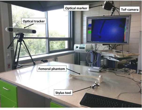
The registration system (Fig 1) consists of three different data sources used to represent the object of interest: SwissRanger SR4000 ToF-camera (MESA Imaging AG, Switzerland,http:// www.mesa-imaging.ch), the Polaris Spectra navigation system (Northern Digital Inc., ON, Canada,http://ndigital.com) and the CT scanning in a pre-operative mode. These three acqui-sition techniques are implemented to receive three point clouds of an object. In this study phantoms of the following human organs have been employed: (1) the femur and patella, (2) the upper limb, (3) the head, and (4) the breast. The phantoms are made of various plastic materials, both rigid and flexible.
The ToF-sensor produces a depth data matrix ((x,y,z) coordinates) at 176 × 144 pixel reso-lution as well as the amplitude (intensity) image and a confidence value for each acquired point. The optical tracker finds the position and orientation of a tool by following the optical marker location. Once sliding the tool along the phantom, its surface is scanned, yielding point cloud.
Registration system
The registration system employing ToF and marker-driven optical tracker requires a fast, robust and repeatable calibration procedure. Thus, the intrinsic parameters of the ToF-camera as well as the position of the ToF-camera within the tracker coordinate systems (extrinsic parameters) are found.
ToF-camera intrinsic parametersThe ToF-camera acquires the image depths as well as grayscale intensities of corresponding pixels. With these images, the camera pose is established using OpenCV toolkit (http://opencv.org) according to the pinhole model. Intrinsic parameters are the camera features, which do not depend on the scene viewed, but only on the camera optics itself. They include the focal length, principal point of the optical axis, distortion coeffi-cients. Once estimated, they are valid until the focal length (i.e.zoom) changes.
Computation of intrinsic parameters is performed in a standard way with a set of grayscale chessboard images [49] using the implementation provided by OpenCV. Due to the low con-trast and spatial resolution of images (144 × 176 pixels), the intensity rescaling as well as the image upsampling for subpixel corners detection are performed.
ToF-camera extrinsic parametersOnce the intrinsic parameters are given, the absolute orientation of the camera in the external (i.e.global) coordinate system can be found. Follow-ing the pinhole camera model [49], the relationship between the 3D homogeneous point
PG¼ ½ xG
;y G
;z G
;1
T
in a global coordinate system and its 2D image projection [u,v, 1]Tis given by: s u v 1 2 6 6 6 4 3 7 7 7 5
¼MIME
xG yG zG 1 2 6 6 6 6 6 6 6 4 3 7 7 7 7 7 7 7 5
; ð1Þ
whereMIandMEare the matrices of intrinsic and extrinsic coefficients, respectively, andsis the scale factor. The correction of lens distortions is performed according to [49].
To compute the matrix of extrinsic parameters, one has to match the set of 3D points recorded by the tracker and their corresponding coordinates in the ToF intensity image, known as,,Perspective-n-Point problem”(PnP) [50]. For this, the inner corners of the calibra-tion chessboard are used, since they can be easily detected in the image and their posicalibra-tion in the tracker coordinate system can be precisely acquired with pre-calibrated stylus tool.
The extrinsic parameters matrixMEcan be extended to a rigid-body transformation matrix
TC
Gby adding a row [0, 0, 0, 1] at the bottom.T C
Gis orthogonal and denotes rotation and
trans-lation of the camera with respect to the global coordinate system (Fig 1). The coordinates of a pointPG ¼ ð
xG ;y
G ;z
GÞ
given in global coordinate system can be transformed into a point
PC
¼ ðxC ;y
C ;z
C
Þin the ToF-camera coordinate systemC:
PC¼ TC
GP G
: ð2Þ
The direction of transformation can easily be inverted:
PG
¼TG CP
C
; ð3Þ
whereTG C ¼ ðT
C GÞ
1
.
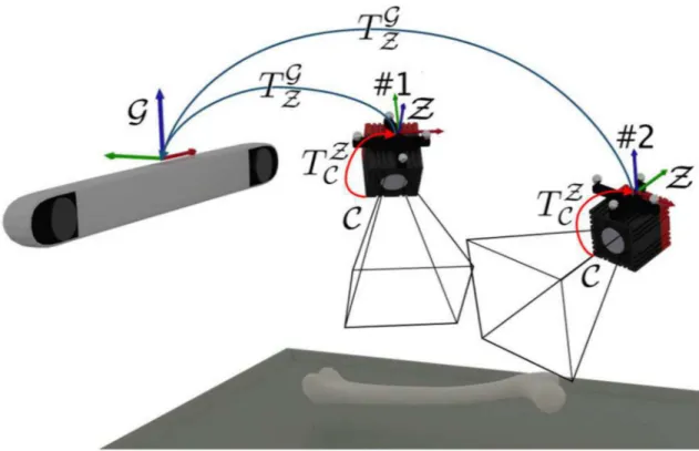
Since the extrinsic parameters are related to global coordinate system, their values are valid only as long as the spatial relation between the ToF-camera and the tracker does not change. To make the processing stable and universal, an additional coordinate system is introduced. It
Fig 1. Experimental setup.
remains invariant with respect to the ToF-camera, regardless of the camera movement in a global tracker space. The coordinate system is constructed by the optical tracker marker fixed onto the ToF-camera. This enables the extrinsic parameters determination with respect to the marker and then both, the tracker and the ToF-camera can freely be moved around (Fig 2). Therefore, the extrinsic parameters matrix denotes the transformationTZ
C of points registered
by the camera (coordinate systemC) into the camera marker coordinate systemZ:
PZ
¼TZ CP
C
: ð4Þ
As long as the camera marker remains visible for the tracker, the transformationðTG
ZÞτbetween
the marker and global coordinate system in timeτis known. Then, we can transfer each point
acquired by the ToF-camera directly into the global coordinate system:
PG ¼ ð TG
ZÞτT Z CP
C
: ð5Þ
Data registration
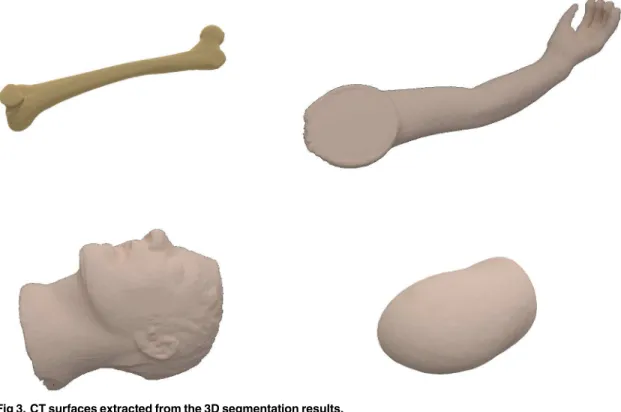
Data pre-processingBoth, the preoperative CT and ToF data require robust segmentation pro-cedures in order to minimize the influence of noise and unwanted structures within the acquired data. The CT segmentation step uses a thresholding technique based on Hounsfield units sup-ported by mathematical morphology to extract the 3D phantom object. Since all phantoms sub-jected to the segmentation feature the mean density over 0 HU, they are extracted from the surrounding air (density not exceeding−800 HU) using the automatic Otsu thresholding tech-nique [51] (threshold values ranged between−600 and−550 HU) followed by morphological
Fig 2. Transformations between different coordinate systems.Once estimated, the transformationTZ
C between
ToF-cameraCand the markerZcoordinate systems remains invariant, despite of the camera movement relative to the global coordinate systemG.
doi:10.1371/journal.pone.0159493.g002
corrections and 2D/3D connected component analysis. Since the registration step requires a sur-face object representation, the outer sursur-face is extracted from the object (Fig 3).
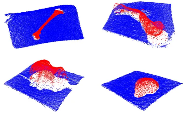
The other 3D segmentation algorithm is applied to the ToF data analysis. In order to reduce the effect of depth inhomogeneity, which leads to incorrect distance values at object boundaries (“flying pixels”) [21], the confidence map provided by the camera is used. The point coordi-nates within the ToF-camera coordinate system and amplitude image are merged in the feature space. Such a two-element feature vector is then subjected to a Weighted Fuzzy C-Means (WFCM) [4,52] clustering procedure leading to segmentation results shown inFig 4.
The values of coordinates within the optical tracker system are collected by sliding a stylus tool against the phantom surface. Sample point cloud in a 3D view is shown inFig 5. One can see the trajectories of the stylus tool recorded during the points collection.
ICP registrationThe image registration that matches the ToF-camera image (Fig 4) to the CT phantom image (Fig 3) and the point cloud acquired by the optical tracker (Fig 5) is based on the meshes geometry. For this, the ICP (Iterative Closest Point) technique has been chosen [53]. In our study the initial pose is defined by the camera set-up pre-alignment step. The structure of acquired datasets imposes a point-to-point solution [45,54].
The ICP technique consists of six steps [54]: (1) selection of set of points to be registered in one or both meshes, (2) matching the points between meshes, (3) weighting the corresponding pairs of points, (4) rejecting certain pairs, (5) assigning an error metrics based on pairs of points, and (6) minimizing the error metrics. Each of these steps can differently affect the regis-tration performance. In our approach various methods have been employed at these steps. The selection of points to be registered in both meshes is performed in the pre-segmentation step. As recommended in [43], all points yielded by the pre-segmentation are used for further regis-tration. The matching of points between meshes is performed by ak-dimensional tree algo-rithm [55] applied in order to increase the speed of the nearest neighbour search. The constant
Fig 3. CT surfaces extracted from the 3D segmentation results.
Fig 4. ToF depth images segmentation results in a 3D view.
doi:10.1371/journal.pone.0159493.g004
Fig 5. Point clouds from optical tracker in a 3D view.
doi:10.1371/journal.pone.0159493.g005
weight used to describe the corresponding pairs is then followed by rejecting 5% of the worst pairs of points in terms of the Euclidean distance. The root-mean-square error (RMSE) is used to evaluate distances between corresponding points. The optimal rotation between points is found using the Singular Value Decomposition (SVD) [56]. Since we do not focus on the con-vergence speed of the ICP algorithm, the registration is preceded by the pre-alignment result-ing in initial rotation matrix estimation.
Results
The accuracy and robustness of the registration procedure in medical applications were tested using four phantoms introduced in Section Materials and Methods. In each case all three acquisition techniques (ToF-camera, optical tracker, CT) produced the point clouds. We com-pared and evaluated registration accuracies of each of three pairs of datasets in terms of Haus-dorff distance [34] and mean absolute distance [57]. For given two finite point sets (surfaces)
A= {a1,. . .,an} andB= {b1,. . .,bm}, the directed Hausdorff distance (HD) is defined as:
HDðA;BÞ ¼max
ai2A
min
bj2B kai bjk; ð6Þ
wherekkis the Euclidean norm on the points ofAandB. The mean absolute distance (MAD) for a pair of surfacesAandBis the mean of the distance values fromAtoBfor allnvoxels in
A:
MADðA;BÞ ¼
1
n Xn
i¼1
min
bj2B
kai bjk: ð7Þ
The pairwise registration between each: ToF, CT, and optical tracker in both directions yielded six pairs of metrics values labelled as:“CT to Opt”,“Opt to CT”,“Opt to ToF”,“ToF to Opt”,“ToF to CT”, and“CT to ToF”. Precision of the ToF-camera calibration step and its influence on the accuracy of further inter-sensor analysis and registration was evaluated, as described below.
Two system set-ups varying in position of the phantoms, ToF-camera and optical tracker are denoted asPos.#1andPos.#2(#1 and #2 inFig 2, respectively) in further discussion and presentation of results. The numerical results for the manual correction influence analysis are labelledRaw(if no correction is introduced to the cloud of points) andCorrected(if manual corrections are introduced).
Calibration accuracy
To evaluate the calibration stage, the intrinsic and extrinsic parameters were determined with respect to the reference coordinate systemZdefined by the markerfixed at the camera located
in position #1 (Fig 2). Then, the chessboard corners (testing points), whose positions were acquired by the stylus tool in theZsystem, were projected (PnP, as described in Section
Regis-tration system) to the 2D amplitude imageJ (Fig 6):
PJ
i ¼PnPðP
Z
i ;MI;MEÞ; ð8Þ
whereMIandMEare the matrices of intrinsics and extrinsics. Coordinates of both, 2D testing points found in the amplitude image and projections of their corresponding 3D points, were compared in terms of their Euclidean distance. The mean distance is shown in thefirst row of
Table 1.
transformed to theZcoordinate system using previous calibration parameters. At position #2
of the camera (Fig 2), projection of the imageJ was found as:
PJ
i ¼PnPððT
Z GÞτP
G
i;MI;MEÞ; ð9Þ
whereMIandMEwere obtained from camera position 1, andðTGZÞτdenotes the current camera
position (#2) in the global coordinate system (see Section Registration system). Again, Euclid-ean distances were determined between the 2D testing points and the projections of their corre-sponding 3D points, whose location was changed.
The entire procedure described above was repeated after switching positions #1 and #2. The projection errors obtained during all four validation steps are presented inTable 1. As
expected, the calibration process is saddled with a low transformation error in the image plane, whereas the depth error is much higher. The obtained pre-alignment enables a further robust
Fig 6. ToF-camera amplitude image with (rounded to full pixels) corresponding 3D points.
doi:10.1371/journal.pone.0159493.g006
Table 1. Mean projection errors obtained using two camera positions for calibration and validation (Fig 2).
Calibration position Validation position Mean error±std. dev. [px]
#1 #1 0.26±0.13
#1 #2 0.27±0.08
#2 #1 0.66±0.21
#2 #2 0.15±0.08
doi:10.1371/journal.pone.0159493.t001
registration step. This analysis is specially important for symmetrical/pseudo-symmetrical structures where the ICP technique leads to an error resulting from rotation perpendicular to the axis of the visualized object. On the other hand, the depth error caused by the calibration step can easily be corrected by the ICP technique.
The obtained misalignments between ToF and optical tracker point clouds are presented in
Table 2. TheHDandMADvalues are determined in three variants of setAfrom Eqs (6) and (7): with 0%, 3% and 10% (denoted aspm) of the worst matches rejected [13]. The relatively large misalignment results are improved by further surface registration step in terms of the ICP technique.
ICP registration results
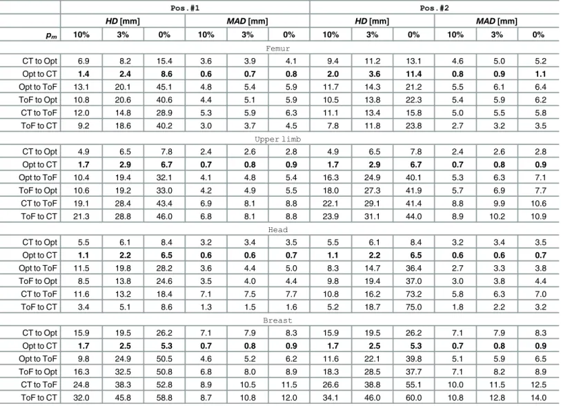
The ICP registration accuracies of each of the three pairs of data were evaluated for all phan-toms. Results obtained for two experimental set-upsPos.#1andPos.#2are shown in
Table 3. We presentHDandMADvalues calculated for registered point clouds if the worst 10%, 3% and 0% percentile of points (denoted aspm) is rejected. ExtendedHDandMAD results presentation for femoral phantom are provided in Figs7and8As the ICP registration is not symmetrical, theHDandMADvalues are computed twice for each pair of data (in both directions).
Although it is common to reject the worst 10% of matches to get accurate results [13], one can see inTable 3that only last 3% of matches have the greatest impact on theHDvalue.
The best alignment results atpm= 10% are obtained if registration from the tracker to CT is performed, yieldingHDvalues equal to 1.1 mm and 2.4 mm in the best and the worst case, respectively. In the opposite direction theHDresults are substantially higher (2.4–15.9 mm). However, if the ToF-sensor data are registered, theHDvalues range from 3.4 to 34.1 mm.
TheMADmetrics indicates the level of shape correspondence between surfaces yielded by each acquisition technique. TheMADconsistently below 1 mm in case of a CT and optical tracker registration ought to be considered as rewarding. In general, most of the mean absolute distances are below 1 cm. The only exceptions from the above rule are related to the ToF cam-era and they result from its acquisition inaccuracy [21].
The visualisations of all three registered point clouds are shown for each phantom inFig 9.
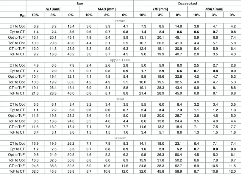
The influence of manual data correction
Since in medical applications automated procedures are often followed by manual corrections [58], we included the adequate analysis in our experiments. Two registered point clouds: ToF-data and optical tracker ToF-data were pre-processed by the manual removal of outliers. The points were removed by a medical and computer vision expert. The obtained results are labelled as CorrectedinTable 4, as well as are shown inFig 10. No significant improvement of the
Table 2. ToF-to-optical tracker misalignment summary after ToF camera calibration.
HD[mm] MAD[mm]
pm 10% 3% 0% 10% 3% 0%
Femur 15.8 26.9 48.8 7.0 8.0 8.9
Upper limb 47.6 58.9 68.2 15.6 18.2 19.6
Head 18.9 23.2 32.6 8.7 9.6 10.1
Breast 89.1 105.9 116.6 40.0 44.1 46.1
Results obtained for raw data withpmequal to 10%, 3% and none of the worst matches removed.
results is observed. TheHDatpm= 10% after manual correction differs from the raw data results by not more than 1.8 mm, yet in most cases the difference barely exceeds 0.5 mm. Tak-ingMADinto account, the influence of manual data correction is even less noticeable— respec-tive values differs mostly not more than by 0.2 mm.
Discussion
The goal of this paper was to investigate the surface matching using CT, ToF and the optical navigation system in a real environment and to test its applicability for medical data registra-tion. The study results provide a comparison of accuracy estimates for three combinations of surface alignment. Since the phantoms were scanned repeatedly in various positions, we got also some information on the robustness of the registration systems. Finally, the impact of manual correction of the image data on the overall accuracy was tested. Although all the
Table 3. ICP registration results in various ToF camera positions.
Pos.#1 Pos.#2
HD[mm] MAD[mm] HD[mm] MAD[mm]
pm 10% 3% 0% 10% 3% 0% 10% 3% 0% 10% 3% 0%
Femur
CT to Opt 6.9 8.2 15.4 3.6 3.9 4.1 9.4 11.2 13.1 4.6 5.0 5.2
Opt to CT 1.4 2.4 8.6 0.6 0.7 0.8 2.0 3.6 11.4 0.8 0.9 1.1
Opt to ToF 13.1 20.1 45.1 4.8 5.4 5.9 11.7 14.3 21.2 5.5 6.1 6.4
ToF to Opt 10.8 20.6 40.6 4.4 5.1 5.9 10.5 13.8 22.3 5.4 5.9 6.2
CT to ToF 12.0 14.8 28.9 5.3 5.9 6.3 11.1 13.4 15.8 5.0 5.5 5.8
ToF to CT 9.2 18.6 40.2 3.0 3.7 4.5 7.8 11.8 23.8 2.7 3.2 3.5
Upper limb
CT to Opt 4.9 6.5 7.8 2.4 2.6 2.8 4.9 6.5 7.8 2.4 2.6 2.8
Opt to CT 1.7 2.9 6.7 0.7 0.8 0.9 1.7 2.9 6.7 0.7 0.8 0.9
Opt to ToF 10.4 19.4 32.1 4.1 4.8 5.4 16.3 24.9 40.1 5.3 6.3 7.1
ToF to Opt 10.6 19.2 33.0 4.2 4.9 5.5 18.0 27.3 41.9 5.7 6.9 7.7
CT to ToF 19.1 28.4 43.4 6.9 8.1 8.8 22.1 29.1 41.4 8.8 9.9 10.6
ToF to CT 21.3 28.8 46.0 6.8 8.1 8.8 23.9 31.1 44.0 8.9 10.2 10.9
Head
CT to Opt 5.5 6.1 8.4 3.2 3.4 3.5 5.5 6.1 8.4 3.2 3.4 3.5
Opt to CT 1.1 2.2 6.5 0.6 0.6 0.7 1.1 2.2 6.5 0.6 0.6 0.7
Opt to ToF 11.5 19.8 28.2 3.6 4.4 5.0 8.3 14.7 36.4 2.7 3.3 3.8
ToF to Opt 8.5 13.8 24.6 3.5 4.0 4.4 9.8 19.4 37.0 3.0 3.8 4.4
CT to ToF 11.6 13.2 18.4 7.1 7.5 7.7 10.8 16.2 73.2 5.8 6.3 7.0
ToF to CT 3.4 5.1 8.6 1.3 1.5 1.6 5.2 18.7 75.0 1.8 2.2 3.2
Breast
CT to Opt 15.9 19.5 26.2 7.1 7.9 8.3 15.9 19.5 26.2 7.1 7.9 8.3
Opt to CT 1.7 2.5 5.3 0.7 0.8 0.9 1.7 2.5 5.3 0.7 0.8 0.9
Opt to ToF 9.8 24.9 50.5 4.6 5.2 6.2 11.6 22.1 39.8 5.1 5.9 6.5
ToF to Opt 16.3 32.5 50.8 6.8 8.0 8.9 18.3 28.5 37.7 7.1 8.2 8.9
CT to ToF 24.8 38.3 52.8 8.9 10.5 11.5 26.6 38.8 55.1 10.0 11.5 12.5
ToF to CT 32.0 45.8 58.8 8.7 10.8 12.0 34.1 46.0 60.0 10.8 12.8 14.0
Results are estimated for all ICP registrations performed over raw data with 10%, 3% and 0% of the worst matches (pm) removed.Pos.#1andPos.#2refer
to two different positions of the phantom and sensors.
doi:10.1371/journal.pone.0159493.t003
Fig 7. Results of the first experimental set-up on femoral phantom (Pos.#1).HDandMADbetween each pair of registered point clouds with the percentilepmof worst matches removed. Plotted at the full range (top) and zoomed to the [0.9, 1.0] range ofpm(bottom).
doi:10.1371/journal.pone.0159493.g007
Fig 8. Results of the second experimental set-up on femoral phantom (Pos.#2).HDandMADbetween each pair of registered point clouds with the percentilepmof worst matches removed. Plotted at the full range (top) and zoomed to the [0.9, 1.0] range ofpm(bottom).
analysed image modalities and sensor data are already applied in medical field [47,48], the introduced combination of them stands for the original contribution and features some signifi-cant potential for image guided surgery systems.
For the numerical analysis we used the ICP algorithm enabling fast and robust rigid regis-tration whose accuracies evaluated by Hausdorff andMADdistances proved usefulness of the multi-sensors visualization system. However, it has to be noticed, that in order to achieve high quality of the multi-sensors system, additional issues have to be addressed.
Since the overall idea of the study was to determine the maximum accuracy of the multi-sensor system, the results originate from the phantom experiments. However, in clinical set-tings one deals with various types of patient-related motions, time constrains, unforeseen events that may challenge the workflow. Further studies are required to improve the accuracy by employing a second ToF-camera [48].
Shapes of the phantoms are non-symmetrical and variform, yet the phantoms’materials are very easy to segment from CT scans itself. Diverse shapes resemble the limitations of measure-ment performed with an optical tracker, indicating the angle of optical marker, number of measurement points, or the difficulties of the object surface scanning by the optical marker.
The ToF-sensor is a relatively cheap and safe tool to align the intra-operative surface onto the pre-segmented CT data and can be used in cooperation with the optical tracker or as a stand-alone device. However, to employ it in medical application some of its constraints have to be considered. According to our registration accuracy measurements, despite the relatively low resolution of the camera’s CCD and high level of noise, the ToF-sensor is suitable mostly for the pre-alignment of registered surfaces. The ToF sensor calibration is required in order to
Fig 9. Visualisation of the registration results.ToF data (red), CT data (green), optical tracker data (blue).
doi:10.1371/journal.pone.0159493.g009
obtain direct transformation formula between both acquisition systems (ToF-sensor and opti-cal tracker). It is particularly important for the analysis of the almost symmetriopti-cal structures for which the ICP algorithm may result in a reversal along their axis of symmetry.
The effect of depth inhomogeneity leading to wrong distance measurements at object boundaries has to be reduced in order to obtain the accurate ToF point cloud segmentation. It can be done on the basis of a confidence map provided by the sensor. This confidence informa-tion is also important in the context of curvature of visible space at the depth image edges. The accuracy of a ToF-camera varies with respect to the direction of the recorded structure. The depth error is substantially higher than the error in the image plane [21]. Thus, the spatial ori-entation of segmented structure is relatively correctly measured, whilst the translation in depth-direction causes most of the total error.
It is also noteworthy, that if the optical tracker and the ToF-camera using infra-red light are running together at the same time, they may disturb each other’s measurements. The
Table 4. The influence of manual data corrections on ICP registration.
Raw Corrected
HD[mm] MAD[mm] HD[mm] MAD[mm]
pm 10% 3% 0% 10% 3% 0% 10% 3% 0% 10% 3% 0%
Femur
CT to Opt 6.9 8.2 15.4 3.6 3.9 4.1 7.3 8.5 14.8 3.8 4.1 4.2
Opt to CT 1.4 2.4 8.6 0.6 0.7 0.8 1.4 2.4 8.6 0.6 0.7 0.8
Opt to ToF 13.1 20.1 45.1 4.8 5.4 5.9 13.1 20.1 45.1 5.9 6.6 7.4
ToF to Opt 10.8 20.6 40.6 4.4 5.1 5.9 10.7 20.2 41.3 4.4 5.1 5.8
CT to ToF 12.0 14.8 28.9 5.3 5.9 6.3 12.4 15.1 30.9 5.4 5.9 6.4
ToF to CT 9.2 18.6 40.2 3.0 3.7 4.5 9.0 19.9 40.7 2.8 3.5 4.3
Upper limb
CT to Opt 4.9 6.5 7.8 2.4 2.6 2.8 5.0 5.9 8.0 2.5 2.7 2.8
Opt to CT 1.7 2.9 6.7 0.7 0.8 0.9 1.7 2.9 6.6 0.7 0.8 0.9
Opt to ToF 10.4 19.4 32.1 4.1 4.8 5.4 9.9 19.6 32.8 4.0 4.7 5.3
ToF to Opt 10.6 19.2 33.0 4.2 4.9 5.5 10.0 19.5 32.5 4.0 4.7 5.3
CT to ToF 19.1 28.4 43.4 6.9 8.1 8.8 19.1 28.3 43.4 6.9 8.1 8.8
ToF to CT 21.3 28.8 46.0 6.8 8.1 8.8 21.4 28.9 45.9 6.8 8.1 8.8
Head
CT to Opt 5.5 6.1 8.4 3.2 3.4 3.5 5.5 6.0 8.4 3.2 3.4 3.5
Opt to CT 1.1 2.2 6.5 0.6 0.6 0.7 2.4 3.4 7.3 1.1 1.2 1.3
Opt to ToF 11.5 19.8 28.2 3.6 4.4 5.0 11.5 20.0 28.7 3.6 4.5 5.0
ToF to Opt 8.5 13.8 24.6 3.5 4.0 4.4 8.6 13.8 24.4 3.5 4.0 4.4
CT to ToF 11.6 13.2 18.4 7.1 7.5 7.7 11.6 13.2 18.4 7.1 7.5 7.7
ToF to CT 3.4 5.1 8.6 1.3 1.5 1.6 3.4 5.1 8.6 1.3 1.5 1.6
Breast
CT to Opt 15.9 19.5 26.2 7.1 7.9 8.3 14.1 18.0 23.1 6.4 7.1 7.4
Opt to CT 1.7 2.5 5.3 0.7 0.8 0.9 1.6 2.3 5.2 0.7 0.8 0.8
Opt to ToF 9.8 24.9 50.5 4.6 5.2 6.2 9.5 26.3 50.4 4.5 5.2 6.1
ToF to Opt 16.3 32.5 50.8 6.8 8.0 8.9 15.9 31.8 50.2 6.6 7.8 8.7
CT to ToF 24.8 38.3 52.8 8.9 10.5 11.5 24.8 38.3 52.7 8.9 10.5 11.5
ToF to CT 32.0 45.8 58.8 8.7 10.8 12.0 32.0 45.8 58.9 8.7 10.8 12.0
Results are estimated for all ICP registrations performed over raw data (Raw) and data with outliers removed manually (Corrected) with 10%, 3% and 0% of the worst matches (pm) removed. All experiments for the ToF camera positionPos.#1.
interferences may occur if the optical marker is located exactly between the lenses of the devices. The exact analysis of the interferences will be performed in future studies.
Calibrated ToF-camera is a device which could be potentially deployed at the stage of position-ing an object in the navigation system space. The results from Tables3and4confirm, that the worst alignment between optical tracker and ToF camera (1.8 cm,pm= 10%) is at the level of acceptance even in some medical fields [11]. Moreover, our experiments showed that if the num-ber of rejected points is decreased to 3%, the misalignment is still acceptable. A period of surface acquisition is much shorter than the duration of pointing the stylus tool at the body’s landmarks. Also, the point cloud obtained by ToF-camera contains significantly more elements than the usual number of landmarks. The registration process performed by surface matching yields results not worse than landmark-based registration [25]. This could allow the stylus tool to be replaced by a ToF-camera during object calibration. This will be investigated in the further research.
Conclusion
In the paper, we present the first study on the abilities of three-modal surface registration using: CT scanning in a pre-operative mode, the SwissRanger SR4000 ToF-camera and the Polaris Spectra navigation system. The multi-sensors data analysis in medical field opens new possibilities in minimally invasive surgery, giving the feedback concerning pre- and intra-oper-ative data correspondence. The proposed experimental set-up gives the reader information concerning some limitations of the system, possible problems to be addressed and solutions how to deal with them. The obtained pairwise inter-modality alignment accuracies at a few mil-limeter range allow us to conclude, that together with technological advancement of ToF-cam-eras, they are going to be used increasingly in various fields of medicine.
Fig 10. Results of the first experimental set-up on femoral phantom with manually removed outliers (Pos.#1,Corrected).HDandMAD
between each pair of registered point clouds with the percentilepmof worst matches removed. Plotted at the full range (top) and zoomed to the [0.9, 1.0]
range ofpm(bottom).
doi:10.1371/journal.pone.0159493.g010
Author Contributions
Conceived and designed the experiments: BP JC. Performed the experiments: BP JC PB JJ. Analyzed the data: BP JC PB JJ EP. Wrote the paper: BP JC PB JJ EP.
References
1. Zarychta P. Automatic registration of the medical images—T1- and T2-weighted MR knee images. In: Napieralski A, editor. Proceedings of the International Conference Mixed Design of Integrated Circuits and Systems; 2006. p. 741–745. Available from:http://dx.doi.org/10.1109/MIXDES.2006.1706684. 2. Markelj P, TomaževičD, Likar B, PernušF. A review of 3D/2D registration methods for image-guided
interventions. Medical Image Analysis. 2012; 16(3):642–661. Computer Assisted Interventions. doi:10. 1016/j.media.2010.03.005PMID:20452269
3. Song Y, Totz J, Thompson S, Johnsen S, Barratt D, Schneider C, et al. Locally rigid, vessel-based reg-istration for laparoscopic liver surgery. International Journal of Computer Assisted Radiology and Sur-gery. 2015; 10(12):1951–1961. doi:10.1007/s11548-015-1236-8PMID:26092658
4. Czajkowska J, Pycinski B, Pietka E. HoG Feature Based Detection of Tissue Deformations in Ultra-sound Data. In: 2015 37th Annual International Conference of the IEEE Engineering in Medicine and Biology Society (EMBC); 2015. p. 6326–6329. Available from:http://dx.doi.org/10.1109/embc.2015. 7319839.
5. Feuerstein M, Mussack T, Heining SM, Navab N. Intraoperative Laparoscope Augmentation for Port Placement and Resection Planning in Minimally Invasive Liver Resection. Medical Imaging, IEEE Transactions on. 2008 March; 27(3):355–369. doi:10.1109/TMI.2007.907327
6. LangøT, Vijayan S, Rethy A, Våpenstad C, Solberg O, Mårvik R, et al. Navigated laparoscopic ultra-sound in abdominal soft tissue surgery: technological overview and perspectives. International Journal of Computer Assisted Radiology and Surgery. 2012; 7(4):585–599. doi:10.1007/s11548-011-0656-3 PMID:21892604
7. Sorger H, Hofstad EF, Amundsen T, LangøT, Leira HO. A novel platform for electromagnetic navigated ultrasound bronchoscopy (EBUS). Int J CARS. 2015 nov; doi:10.1007/s11548-015-1326-7
8. Baumhauer M, Simpfendorfer T, Muller-Stich BP, Teber D, Gutt CN, Rassweiler J, et al. Soft tissue nav-igation for laparoscopic partial nephrectomy. International Journal of Computer Assisted Radiology and Surgery. 2008; 3(3–4):307–314. doi:10.1007/s11548-008-0216-7
9. Wood BJ, Kruecker J, Abi-Jaoudeh N, Locklin JK, Levy E, Xu S, et al. Navigation Systems for Ablation. Journal of Vascular and Interventional Radiology. 2010; 21(8, Supplement):S257–S263. Thermal Abla-tion 2010: At the Crossroads of Past Success, Current Goals, and Future Technology. doi:10.1016/j. jvir.2010.05.003PMID:20656236
10. Sindram D, McKillop IH, Martinie JB, Iannitti DA. Novel 3-D laparoscopic magnetic ultrasound image guidance for lesion targeting. HPB. 2010; 12(10):709–716. doi:10.1111/j.1477-2574.2010.00244.x PMID:21083797
11. Pycinski B, Juszczyk J, Bozek P, Ciekalski J, Dzielicki J, Pietka E. Image Navigation in Minimally Inva-sive Surgery. In: Information Technologies in Biomedicine Volume 4. vol. 284 of Advances in Intelligent Systems and Computing. Springer International Publishing; 2014. p. 25–34. Available from:http://dx. doi.org/10.1007/978-3-319-06596-0_3.
12. Mersmann S, Seitel A, Erz M, Jahne B, Nickel F, Mieth M, et al. Calibration of time-of-flight cameras for accurate intraoperative surface reconstruction. Med Phys. 2013; 40(8):082701. doi:10.1118/1. 4812889PMID:23927355
13. dos Santos TR, Seitel A, Kilgus T, Suwelack S, Wekerle AL, Kenngott H, et al. Pose-independent sur-face matching for intra-operative soft-tissue marker-less registration. Medical Image Analysis. 2014 oct; 18(7):1101–1114. doi:10.1016/j.media.2014.06.002PMID:25038492
14. Lin HH, Lo LJ. Three-dimensional computer-assisted surgical simulation and intraoperative navigation in orthognathic surgery: A literature review. Journal of the Formosan Medical Association. 2015; 114 (4):300–307. doi:10.1016/j.jfma.2015.01.017PMID:25744942
15. Maurer CR Jr, Fitzpatrick JM, Wang MY, Galloway RL, Maciunas RJ, Allen GS. Registration of head volume images using implantable fiducial markers. Medical Imaging, IEEE Transactions on. 1997; 16 (4):447–462. doi:10.1109/42.611354
17. Guo C, Cheng Y, Guo H, Wang J, Wang Y, Tamura S. Surface-based rigid registration using a global optimization algorithm for assessment of MRI knee cartilage thickness changes. Biomedical Signal Pro-cessing and Control. 2015; 18:303–316. doi:10.1016/j.bspc.2015.02.007
18. Cash DM, Miga MI, Sinha TK, Galloway RL, Chapman WC. Compensating for intraoperative soft-tissue deformations using incomplete surface data and finite elements. Medical Imaging, IEEE Transactions on. 2005 Nov; 24(11):1479–1491. doi:10.1109/TMI.2005.855434
19. Spinczyk D, Karwan A, Zylkowski J, Wroblewski T. Experimental study In-vitro evaluation of stereo-scopic liver surface reconstruction. Videosurgery and Other Miniinvasive Techniques. 2013; 1:80–85. doi:10.5114/wiitm.2011.32809
20. Groch A, Seitel A, Hempel S, Speidel S, Engelbrecht R, Penne J, et al. 3D Surface Reconstruction for Laparoscopic Computer-Assisted Interventions: Comparison of State-of-the-Art Methods. In: Wong K, Holmes D, editors. Medical Imaging 2011: visualization, image-guided procedures, and modeling. vol. 7964 of Proceedings of SPIE. SPIE-INT SOC OPTICAL ENGINEERING; 2011. Available from:http:// dx.doi.org/10.1117/12.878354.
21. Kolb A, Barth E, Koch R,Larsen R. Time-of-Flight Cameras in Computer Graphics. Computer Graphics Forum. 2010 mar; 29(1):141–159. doi:10.1111/j.1467-8659.2009.01583.x
22. Spinczyk D, Karwan A, Copik M. Methods for abdominal respiratory motion tracking. Computer Aided Surgery. 2014 jan; 19(1–3):34–47. doi:10.3109/10929088.2014.891657PMID:24720494
23. Langmann B, Hartmann K, Loffeld O. Increasing the accuracy of Time-of-Flight cameras for machine vision applications. Computers in Industry. 2013; 64(9):1090–1090. Special Issue: 3D Imaging in Indus-try. doi:10.1016/j.compind.2013.06.006
24. Maintz JBA, Viergever MA. A survey of medical image registration. Medical Image Analysis. 1998; 2 (1):1–1. doi:10.1016/S1361-8415(01)80026-8PMID:10638851
25. Audette MA, Ferrie FP, Peters TM. An algorithmic overview of surface registration techniques for medi-cal imaging. Medimedi-cal Image Analysis. 2000; 4(3):201–201.
26. Badura P, Pietka E. Semi-Automatic Seed Points Selection in Fuzzy Connectedness Approach to Image Segmentation. In: Computer Recognition Systems 2 (Advances in Soft Computing). vol. 45. Springer-Verlag; 2007. p. 679–686.
27. Czajkowska J, Badura P, Pietka E. 4D Segmentation of Ewing’s Sarcoma in MR Images. In: Informa-tion Technologies in Biomedicine: Volume 2 (Advances in Intelligent and Soft Computing). vol. 69. Springer-Verlag; 2010. p. 91–100.
28. Wieclawek W, Pietka E. Fuzzy Clustering in Segmentation of Abdominal Structures Based on CT Stud-ies. In: Pietka E and Kawa J, editor. Information Technologies in Biomedicine. vol. 47 of Advances in Intelligent and Soft Computing; 2008. p. 93–104.
29. Kumar SN, Lenin Fred A. Soft computing based segmentation of anomalies on abdomen CT images. In: International Conference on Information Communication and Embedded Systems (ICICES2014). Institute of Electrical & Electronics Engineers (IEEE); 2014. Available from:http://dx.doi.org/10.1109/ icices.2014.7034026.
30. Bohm W, Farin G, Kahmann J. A survey of curve and surface methods in CAGD. Computer Aided Geo-metric Design. 1984; 1(1):1–1. doi:10.1016/0167-8396(84)90003-7
31. Kawa J, Juszczyk J, Pycinski B, Badura P, Pietka E. Radiological Atlas for Patient Specific Model Gen-eration. In: Pietka E, Kawa J, Wieclawek W, editors. Information Technologies in Biomedicine Volume 4. vol. 284 of Advances in Intelligent Systems and Computing. Springer; 2014. p. 69–84. Available from:http://dx.doi.org/10.1007/978-3-319-06596-0_7.
32. Juszczyk J, Pietka E, Pycinski B. Granular computing in model based abdominal organs detection. Computerized Medical Imaging and Graphics. 2015; 46, Part 2. Available from:http://dx.doi.org/10. 1016/j.compmedimag.2015.03.002. PMID:25804441
33. Juszczyk J, Pycinski B, Pietka E. Patient Specific Phantom in Bimodal Image Navigation System. In: 2015 37th Annual International Conference of the IEEE Engineering in Medicine and Biology Society (EMBC); 2015. p. 2908–2911. Available from:http://dx.doi.org/10.1109/EMBC.2015.7319000. 34. Huttenlocher DP, Klanderman GA, Rucklidge W. Comparing Images Using the Hausdorff Distance.
IEEE Trans Pattern Anal Mach Intell. 1993; 15(9):850–863. doi:10.1109/34.232073
35. Spinczyk D. Surface registration by markers guided nonrigid iterative closest points algorithm. In: Emerging Trends in Image Processing, Computer Vision and Pattern Recognition. Elsevier BV; 2015. p. 489–497. Available from:http://dx.doi.org/10.1016/B978-0-12-802045-6.00032-6.
36. Babalola KO, Patenaude B, Aljabar P, Schnabel J, Kennedy D, Crum W, et al. An evaluation of four automatic methods of segmenting the subcortical structures in the brain. NeuroImage. 2009 oct; 47 (4):1435–1447. doi:10.1016/j.neuroimage.2009.05.029PMID:19463960
37. Su LM, Vagvolgyi BP, Agarwal R, Reiley CE, Taylor RH, Hager GD. Augmented Reality During Robot-assisted Laparoscopic Partial Nephrectomy: Toward Real-Time 3D-CT to Stereoscopic Video Regis-tration. Urology. 2009; 73(4):896–896. doi:10.1016/j.urology.2008.11.040PMID:19193404 38. Dumpuri P, Clements LW, Dawant BM, Miga MI. Model-updated image-guided liver surgery:
Prelimi-nary results using surface characterization. Progress in Biophysics and Molecular Biology. 2010; 103 (2–3):197–207. Special Issue on Biomechanical Modelling of Soft Tissue Motion. doi:10.1016/j. pbiomolbio.2010.09.014PMID:20869385
39. Shahriari N, Hekman E, Oudkerk M, Misra S. Design and evaluation of a computed tomography (CT)-compatible needle insertion device using an electromagnetic tracking system and CT images. Interna-tional Journal of Computer Assisted Radiology and Surgery. 2015; 10(11):1845–1852. doi:10.1007/ s11548-015-1176-3PMID:25843947
40. Rucker DC, Wu Y, Clements LW, Ondrake JE, Pheiffer TS, Simpson AL, et al. A Mechanics-Based Nonrigid Registration Method for Liver Surgery Using Sparse Intraoperative Data. Medical Imaging, IEEE Transactions on. 2014 Jan; 33(1):147–158. doi:10.1109/TMI.2013.2283016
41. Gelfand N, Mitra NJ, Guibas LJ, Pottmann H. Robust global registration. In: Proceedings of the Third Eurographics Symposium on Geometry Processing. 197; 2005.
42. Zarychta P, Zarychta-Bargiela A. Automatic registration of the selected human body parts on the basis of entropy and energy measure of fuzziness. In: Programmable Devices and Embedded Systems—
PDeS 2009. Roznov pod Radhostem, Czech Republik: Department of Control and Instrumentation Faculty of Electrical Engineering and Communication, Brno University of Technology; 2009. p. 270–
275.
43. Besl PJ, McKay ND. A Method for Registration of 3-D Shapes. IEEE Trans Pattern Anal Mach Intell. 1992 Feb; 14(2):239–256. doi:10.1109/34.121791
44. Zhang Z. Iterative point matching for registration of free-form curves and surfaces. International Journal of Computer Vision. 1994 oct; 13(2):119–152. doi:10.1007/BF01427149
45. Pomerleau F, Colas F, Siegwart R, Magnenat S. Comparing ICP Variants on Real-world Data Sets. Auton Robots. 2013 Apr; 34(3):133–148. doi:10.1007/s10514-013-9327-2
46. Lago MA, Martinez-Martinez F, Ruperez MJ, Monserrat C, Alcaniz M. Breast prone-to-supine deforma-tion and registradeforma-tion using a Time-of-Flight camera. In: Biomedical Robotics and Biomechatronics (BioRob), 2012 4th IEEE RAS EMBS International Conference on; 2012. p. 1161–1163. Available from:http://dx.doi.org/10.1109/BioRob.2012.6290683.
47. Haase S, Forman C, Kilgus T, Bammer R, Maier-Hein L, Hornegger J. ToF/RGB Sensor Fusion for Augmented 3D Endoscopy using a Fully Automatic Calibration Scheme. In: Tolxdorff T, Deserno TM, Handels H, Meinzer HP, editors. Bildverarbeitung für die Medizin 2012. Informatik aktuell. Springer Berlin Heidelberg; 2012. p. 111–116. Available from:http://dx.doi.org/10.1007/978-3-642-28502-8_21. 48. Placht S, Stancanello J, Schaller C, Balda M, Angelopoulou E. Fast time-of-flight camera based surface
registration for radiotherapy patient positioning. Med Phys. 2012; 39(1):4–17. doi:10.1118/1.3664006 PMID:22225270
49. Zhang Z. A flexible new technique for camera calibration. IEEE Transactions on Pattern Analysis and Machine Intelligence. 2000; 22(11):1330–1334. doi:10.1109/34.888718
50. Lepetit V, Moreno-Noguer F, Fua P. EPnP: An Accurate O(n) Solution to the PnP Problem. International Journal of Computer Vision. 2008 jul; 81(2):155–166. Available from: http://dx.doi.org/10.1007/s11263-008-0152-6.
51. Otsu N. A Threshold Selection Method from Gray-Level Histograms. IEEE Trans Syst, Man, Cybern. 1979; 9(1):62–66. doi:10.1109/TSMC.1979.4310076
52. Czajkowska J, Feinen C, Grzegorzek M, Raspe M, Wickenhöfer R. Skeleton Graph Matching vs. Maxi-mum Weight Cliques aorta registration techniques. Computerized Medical Imaging and Graphics. 2015; 46, Part 2:142–152. Available from:http://dx.doi.org/10.1016/j.compmedimag.2015.05.001. PMID:26099640
53. Chen Y, Medioni G. Object modeling by registration of multiple range images. In: Robotics and Automa-tion, 1991. Proceedings., 1991 IEEE International Conference on; 1991. p. 2724–2729 vol.3. Available from:http://dx.doi.org/10.1109/ROBOT.1991.132043.
54. Rusinkiewicz S, Levoy M. Efficient Variants of the ICP Algorithm. In: Third International Conference on 3D Digital Imaging and Modeling (3DIM); 2001. p. 145–152.
55. Bentley JL. Multidimensional Binary Search Trees Used for Associative Searching. Commun ACM. 1975 Sep; 18(9):509–517. doi:10.1145/361002.361007
57. Gerig G, Jomier M, Chakos M. Valmet: A New Validation Tool for Assessing and Improving 3D Object Segmentation. In: Niessen WJ, Viergever MA, editors. Medical Image Computing and Computer-Assis-ted Intervention—MICCAI 2001: 4th International Conference Utrecht, The Netherlands, October 14–
17, 2001 Proceedings. Berlin, Heidelberg: Springer Berlin Heidelberg; 2001. p. 516–523. Available from:http://dx.doi.org/10.1007/3-540-45468-3_62.
58. Pietka E, Kawa J, Spinczyk D, Badura P, Wieclawek W, Czajkowska J, et al. Role of Radiologists in CAD Life-Cycle. European Journal of Radiology. 2011; 78(2):225–233. doi:10.1016/j.ejrad.2009.08. 015PMID:19783393