F
ACULDADE DEE
NGENHARIA DAU
NIVERSIDADE DOP
ORTODefinition And Adaptation Of 3D
Templates For Synthesizing Human
Activity
Ricardo Miguel Oliveira Rodrigues de Carvalho
D
ISSERTATIONMaster in Informatics and Computing Engineering Supervisor: Luís Corte-Real
Co-Supervisor: Pedro Carvalho External Supervisor: Américo Pereira
c
Definition And Adaptation Of 3D Templates For
Synthesizing Human Activity
Ricardo Miguel Oliveira Rodrigues de Carvalho
Master in Informatics and Computing Engineering
Approved by:
President: Prof. Dr. Jorge Alves da Silva
External Examiner: Prof. Dra. Paula Maria Marques Moura Gomes Viana Referee: Prof. Dr. Pedro Miguel Machado Soares Carvalho
Resumo
A evolução tecnológica recente tornou possível a representação de acontecimentos da vida real em ambientes virtuais. No entanto, para este efeito, é necessária a utilização de software especializado e recursos humanos intensivos. Para representar cenários reais como cenas 3D, as duas possibilidades são o uso de software gráfico 3D ou motores de jogos. Contudo, estas ferramentas requerem conhecimento extenso, não só em áreas como modelação 3D ou animação, mas também conhecimento específico do software utilizado para a tarefa. Além disso, a criação de ambientes em videojogos tipicamente requer que o trabalho seja feito maioritariamente de forma manual, sendo esta uma necessidade inerente ao nível de detalhe pretendido na cena resultante. Não obstante, quando o objetivo da cena é mais informativo que para entretenimento, grande parte deste esforço torna-se redundante dado que alguns detalhes não transmitem informação nova na cena.
A representação sintética de uma cena ou realidade requer vários elementos como entrada, nomeadamente: a descrição dos eventos, incluindo as posições de todas as pessoas e objetos em cada instante, e os modelos 3D de tudo o que é descrito. Naturalmente, criar estes modelos é uma tarefa que pode levar muito tempo, dependendo do nível de detalhe que pode, em certos casos, ser desnecessariamente elevado. Assim, quando se avalia a complexidade da criação deste con-teúdo, torna-se importante encontrar estratégias para simplificar este processo, tornando-o mais rápido e menos custoso. A solução explorada é a criação de uma alternativa a software gráfico 3D que utiliza motores de jogo de forma a reduzir a necessidade de usar ferramentas de edição. Portanto, ao definir templates para objetos e pessoas e um procedimento para automaticamente ajustá-los de acordo com uma descrição, seria possível criar novos conteúdos e adaptar modelos a uma nova representação. Os maiores desafios a ultrapassar prendem-se com a criação e cus-tomização destes modelos e animações. Aquando da sua criação, estes devem ser específicos o suficiente para representar algo concreto, enquanto têm de ser genéricos o suficiente para serem adaptáveis. A dificuldade na customização prende-se com a geração de resultados realistas, por exemplo, adaptar um template de uma pessoa para se enquadrar com uma determinada altura e peso, enquanto mantém a proporção. Após serem personalizados, estes templates podem então ser integrados numa cena 3D para recriar um evento. Seguidamente, utilizadores podem manualmente mudar e adaptar a cena e o seu conteúdo para melhor se adequar às suas ideias. Outros desafios residem em limitações de software e problemas de compatibilidade que limitam algumas possi-bilidades e restringem decisões. Argumentamos que esta solução tem o potencial de simplificar o trabalho necessário para criar ambientes virtuais e, para além de reduzir o investimento temporal e monetário para a sua produção, torna disponível a criação de cenas 3D virtuais para quem tenha interesse, independentemente do conhecimento que tenham na área.
Abstract
Recent technological evolution made it possible to represent real-life scenarios in virtual envi-ronments. However, it is necessary to use specialized software applications and requires intensive human resources. To represent real scenarios as 3D scenes, the two possibilities are to use 3D graphics software or game engines. However, these tools require extensive knowledge, not only in areas such as 3D modeling or animation but also knowledge specific to the software used for the task. Furthermore, the creation of environments in video games typically requires the work to be mostly done by hand, which is a necessity inherent to the level of detail intended for the resulting scene. However, when the goal of the scene is more informative than for entertainment, most of this effort becomes redundant as some details do not add to the information conveyed by the scene. The synthetic representation of a scene or reality requires different elements as inputs, namely: a description of the events, including the positions of every person or object at every instant, and 3D models of everything described. Naturally, creating these models is a task that can be very time consuming, depending on the level of detail which can, sometimes, be unnecessarily high. Ergo, when assessing the complexity of creating this content, it becomes important to find strategies to simplify the process, making it faster and less expensive. The solution explored is the creation of an alternative to 3D graphics software that makes use of game engines to reduce the need for editing tools. Therefore, by defining templates for objects and people and a procedure to automatically adjust them according to a description, one could seamlessly create new content and adapt previous models to a new representation. The biggest challenges to overcome lie within the creation and customization of these models and animations. Upon their creation, they must be specific enough to represent something concrete, whilst being generic enough to be adaptable. The difficulty in the customization is generating realistic results, for instance, adapting a template of a person to fit a certain height and weight, whilst keeping proportion. Once personalized, these templates could then be integrated in a 3D scene to recreate an event. Afterward, users could also manually change and adapt the scene and its content to better fit their ideas. Other challenges reside in software limitations and compatibility issues that limit some possibilities and restrict decisions. We argue that this solution can potentially simplify the work done to create virtual environments and, aside from reducing the time consumption and monetary cost of their production, it also makes available the creation of virtual 3D scenes to whoever has interest despite their knowledge in the area.
Keywords: 3D Model, Game Engine, Graphics Software
Area: CCS - Computing methodologies - Computer graphics - Shape modeling - Mesh geom-etry models
Acknowledgments
Having reached the end of this journey, I would like to express my deepest gratitude to: • my supervisors Professor Luís Corte-Real, Pedro Carvalho and Américo Pereira for all the
support and incentive throughout the preparation and development of this dissertation; • my sister for always being there for me in the best and worst moments even when we are
many kilometers apart;
• my parents for always showing support and being patient with me, specially when nothing was going as planned;
• my colleague Vitor Magalhães for the long hours of discussions about our dissertations and the help and support throughout this process
• all my family for all the care and support you give me everyday that keeps me moving forward;
• my friends for all those welcome moments of incentive and leisure that helped me keep my sanity.
“I have not failed. I’ve just found 10,000 ways that won’t work”
Contents
1 Introduction 1
1.1 Context and Motivation . . . 1
1.2 Objectives . . . 2
1.3 Document Structure . . . 3
2 State of the Art 5 2.1 Introduction . . . 5
2.2 Graphic and Game engines . . . 5
2.3 Procedural Generation . . . 7
2.4 Discussion . . . 9
3 Scene Synthesis Framework 11 3.1 Problem Definition . . . 11 3.2 Proposed Solution . . . 12 3.3 Framework Architecture . . . 13 3.4 Scene Description . . . 14 4 Framework Implementation 19 4.1 Requirements Gathering . . . 19 4.2 Description Processing . . . 21 4.3 Lights Definition . . . 21 4.4 Camera Definition . . . 21 4.5 Objects Definition . . . 23 4.5.1 Geometry Definition . . . 24 4.5.2 Animation Definition . . . 25 4.5.3 Material Definition . . . 26 4.6 Discussion . . . 27
5 Experiments and Results 29 5.1 Scene Generation . . . 29
5.2 Experiments . . . 30
5.3 Evaluation . . . 32
6 Conclusions and Future Work 39
A Simple description Example 41
List of Figures
2.1 Example of image-based reconstruction adapted from [18]. . . 7
2.2 Example of a 3D laser scan of a real-world environment adapted from [17]. . . . 8
2.3 Exemplification of an SMPL Model from [23]. . . 9
3.1 Schematic representation of the process taken towards the automatic creation of a scene. . . 12
3.2 Representation of the possible combinations of height and build in the model of a human. . . 13
3.3 Schematic representation of the interaction between modules. . . 14
3.4 Result of the simple animation described in ListingA.1. . . 18
4.1 Example with different points of view for the same scene. . . 23
4.2 Representation of the three possible levels of detail for a human model. . . 24
4.3 Example of an armature and its application to a human body. . . 25
4.4 Example of the combination of Simple and Complex animations to represent the walking movement. . . 27
4.5 Example of the usage of materials to represent different people’s skin tones and clothing colors. . . 28
5.1 Results obtained for the same scene with three levels of detail. . . 29
5.2 Results obtained for the same animation with three levels of detail. . . 30
5.3 Shopping Center scene generated automatically. . . 31
5.4 Shopping Center scene created by hand. . . 32
5.5 Possible responses to the first question in the questionnaire. . . 33
5.6 The image given in the second question posed to users. . . 34
5.7 Image given in the second question posed to users. . . 35
5.8 Results of the first question of the questionnaire. . . 36
5.9 Results of the second question of the questionnaire. . . 37
List of Tables
2.1 Comparative table with relevant features of graphics and game engines . . . 6 4.1 Details of different light types and required parameters for each, adapted from [24] 22 5.1 Necessary time to import models for the generated scene. . . 31
Abbreviations and Symbols
3D three-dimensionalAPI Application Programming Interface FBX Filmbox
JSON JavaScript Object Notation SMPL Skinned Multi-Person Linear
Chapter 1
Introduction
1.1
Context and Motivation
The technological evolution, mainly of 3D graphic software and game engines, enabled the creation of virtual representations of the real world. This can most commonly be seen in video games and animated videos that usually require high levels of personalization and detail, and in-clude, in the development teams, people solely concerned with the final product’s appearance. The expansion of these powerful technologies to less specialized areas is greatly affected by several factors, some of which will be discussed in the forthcoming paragraphs. The first two to be ad-dressed are the investment of time and the monetary costs inherent when creating content, two aspects that are highly correlated and have a great impact on the decisions made. The third factor is the extensive knowledge required to use graphic software and game engines.
Environment creation in video games, typically requires the work to be done by hand [1]. Even though video games allow greater freedom for exploration, increasing its complexity, both require similar attention to detail, and this implicates great investment in the definition of models for objects and people, and in their placement in the scenes. Ergo, the fidelity of this depiction strongly depends on the size of the team and the number of hours that can be dedicated to the creation of these virtual environments. Notwithstanding, 3D graphic software and game engines are complex tools with capabilities that can be applied beyond their current commercial uses.
Creating content with either graphic software or game engines requires extensive knowledge, not only in areas such as 3D modeling or animation but also with the specific software chosen for the task. There exists a large variety of software dedicated to these areas, with every program being different and having specific ways of achieving the same goals. Anyone who wants to create a simple scene needs to first choose a program, then get acquainted with it and, only then, can they start working on a project. This process can be long, given the complexity of these programs and how overwhelmed one can feel when learning to use them.
The expansion of these tools to new areas is highly conditioned by its complexity. However, it is easy to imagine the usefulness of creating a 3D scene to reconstruct an occurrence or as a way of helping visualize a circumstance. For instance, to help in an investigation, it could be
2 Introduction
useful to recreate an event based on surveillance or witness statements and this recreation could help authorities visualize the occurrence. However, the need to create every element in the virtual scene and placing it in its described position on every instant has a rather negative impact on the usage of these technologies on a regular basis. Thus, it can be important to have some abstraction to the base software to allow the creation of detailed and personalized content without the need for extensive learning.
When facing the complexity of creating this content, it becomes a goal to investigate new ways of simplifying the transformation of real scenes into virtual. Thus, our proposal is to define and implement a mechanism that allows the automatic creation of 3D content in a simpler way, pro-moting an alternative to 3D graphic software and intensive human effort by making use of graphics and game engines to reduce the dependency on editing tools. This framework would introduce the possibility of defining templates of people and objects in 3D that would be automated to allow easy adjustments to adapt, for example, a given description of colours, textures or biometric char-acteristics. These templates could, in their most basic form, be 3D models capable of representing the geometry of a person or object. However, having the goal to represent a described scene, 3D models would have to be subjected to different techniques in order to be adapted to fit their con-text and description. These techniques can range from changes in the geometry of the model to applying different materials and textures to different parts of the model, molding the 3D object to the given description. Furthermore, these templates could be integrated into a scene, recreating an event. For instance, one could recreate historical events based on testimony and descriptions of these situations. Another possible use case is helping an investigation by recreating a situation based solely on witness statements.
Given the aforementioned option’s potential to simplify the work done in the creation of these virtual environments, its usage could also reduce the required time to finish a project, and conse-quently reduce the monetary investment required. This framework’s goal would then be to create any scene using pre-defined templates and basing itself on a given description of the environment to be generated. Therefore, the work to be developed aims to allow an accurate representation of reality based on a set of predefined properties and templates, as well as on a description, as simple as it might be, whilst keeping the level of detail in pivotal features.
1.2
Objectives
This dissertation’s main goal is automating the creation of a virtual visual environment based on a description of its real-world counterpart. This description can have different levels of detail: it can contain just simple details about terrain and objects on it; or, it can contain detailed definitions and textures of an object. Therefore, it is necessary that, by design, templates can be molded to this variety of definitions in order to generate a virtual environment as closely related to the description as possible. To accomplish this goal, several smaller sub-objectives were defined.
The first objective is the definition and implementation of parameterizable templates to be later adapted and used in the synthesis of a scene. These templates are a combination of a pre-defined
1.3 Document Structure 3
3D model and a set of details and techniques. The model consists of the generic geometry of a person or object to be represented in the scene. When joint, these two parts allow the adaptation of the model to fit the description either by using materials and textures or by effectively changing its geometry.
The second objective defined is the synthesis of a static scene using these templates. This sub-objective makes use of the defined templates and aims to provide an approach to combine the definition of individual scene elements with their descriptions relative to each other, mainly their position in the scene. Furthermore, this objective provides the opportunity to automatically render a static scene as an image.
Aiming to increase the level of complexity in each objective, the last objective defined aims to synthesize a dynamic scene based on the defined templates. This objective presents itself as an improvement upon the last one as it allows for more descriptive scenes as they become able to represent an animated scenario.
1.3
Document Structure
The remainder of this document is as follows. In chapter 2, current work and technologies related to the subject are compared and discussed. In chapter3, the problem is described, as well as the solution we proposed to resolve it and the framework’s architecture. In chapter4, details about the implementation process are presented. In chapter 5, the obtained results, the experi-ments done and the results achieved are presented and discussed. In chapter6, a link between the defined objectives and the final result is established, whilst considering potential routes for future
Chapter 2
State of the Art
2.1
Introduction
The proposal of this dissertation focuses on automating and increasing the flexibility of the creation of a virtual scene. To achieve this goal, relevant topics were analyzed, namely: Graphics and Game Engines and Procedural Generation. The following sections will focus on the compari-son of current development tools as well as on the discussion of different techniques that could aid the development process. In section2.2, graphic and game engines will be discussed highlighting their most relevant features. Section2.3compares different approaches to procedural generation, mainly when related to adjusting the geometry of a 3D model. Finally, in section2.4 the infor-mation gathered and presented in both previous sections will be discussed and compared, towards deciding what technologies and techniques are better fitted for the dissertation’s objectives.
2.2
Graphic and Game engines
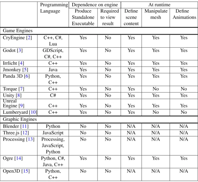
Due to the increasing penetration and availability of computer games, game engines had a significant evolution. Table 2.1 presents a comparison of selected game and graphics engines. This selection focused mostly on the requirement for them to be freeware, as it expands their usability in more complex scenarios. The features most relevant to this dissertation are the level of dependence on the engine and the operations available at runtime. The dependence of the created result on the engine can be evaluated based on whether the engine is capable of generating a standalone executable file – a feature common in game engines but not so common in graphics engines – or, in case that is not a possibility, if the engine is required to view the final result. For instance, Blender [11] is required o open a file with a .blend extension whereas when the project is exported to a standard file extension, such as .fbx, it can be opened with a wide variety of programs. Engines capable of generating a standalone executable implicate that the code used to generate the virtual scene has to run from that executable file and not from within the engine. Ergo, this creates a need to do more extensive testing of functionalities – such as defining a scene content, manipulate a mesh’s geometry or defining animations – to ensure these are made available
6 State of the Art
Table 2.1: Comparative table with relevant features of graphics and game engines Programming
Language
Dependence on engine At runtime Produce Standalone Executable Required to view result Define scene content Manipulate mesh Define Animations Game Engines CryEngine [2] C++, C#, Lua
Yes No Yes Yes Yes
Godot [3] GDScript, C#, C++
Yes No Yes Yes Yes
Irrlicht [4] C++ Yes No Yes Yes Yes
Jmonkey [5] Java Yes No Yes Yes Yes
Panda 3D [6] Python, C++
Yes No Yes Yes Yes
Torque [7] C++ Yes No Yes No No
Unity [8] C# Yes No Yes Yes Yes
Unreal
Engine [9] C++ Yes No Yes Yes Yes
Lumberyard [10] C++ Yes No Yes No No
Graphic Engines
Blender [11] Python No No N/A N/A N/A
Three.js [12] JavaScript No No N/A N/A N/A
Processing [13] Processing, JavaScript,
Python
No No N/A N/A N/A
Ogre [14] Python, C#, Java, C++
Yes No Yes Yes Yes
Open3D [15] Python, C++
No No N/A N/A N/A
at runtime. This need arises from the fact that some engines have a graphical interface with its own set of functionalities that sometimes are not made available in the coding application programming interface (API). For instance, the Unity Engine [8] only allows assets to be imported using its editor, making it impossible to import them at runtime.
As seen in Table 2.1, neither graphic nor game engines are required to view the resulting generated scene. In the case of game engines, this is possible due to their ability to produce a standalone executable file. This is also true for the Ogre [14] engine that, even though it is a graphics engine, allows the use of a plugin to include some game engine features, as well as the ability to generate a standalone executable file. Nevertheless, most graphics engines do not allow the generation of a standalone executable. Instead, these engines are capable of exporting the resulting scenes to a standard format – such as FBX or COLLADA files – or even as an image or video. Two of the runtime features presented: manipulating the mesh’s geometry and defining animations, are less common game engine features and tend to be more closely associated with graphic engines. However, as can be seen in Table2.1, some game engines make them available
2.3 Procedural Generation 7
through plugins or extensions.
2.3
Procedural Generation
One of the major challenges of this dissertation partly stems from the adaptation of a tem-plate to a given description due to the potential complexity of the process. In [16], the author divided the virtual reconstruction of real people and objects into four approaches: manual, image-based, range scanning and procedural. The manual approach is the most traditional, being based on manual skilled labor and requiring intensive human resources. Both image-based and range scanning approaches rely on the existence of a visual element that one intends to represent. The former requires proper image sets with multiple views – as schematized in Figure2.1– and is still time-consuming, while the latter, represented in Figure2.2, requires an additional investment on expensive sensors or data access. An example of range scanning for virtual reconstruction can be found in [17] where the authors compare annual scans of a castle wall to document changes caused by erosion. Lastly, the procedural approach is a mostly automated method whose biggest requirements tend to be computational. Given the scope of this dissertation focusing on automa-tion, Procedural Generation becomes the most promising of these four approaches. Procedural
Figure 2.1: Example of image-based reconstruction adapted from [18].
Generation is a term frequently associated with video-games therefore, many results found were related to this subject. In recent years, re-playability became an important feature in video games, influencing whether people buy them or not [1]. Therefore, to become more attractive, some video
8 State of the Art
Figure 2.2: Example of a 3D laser scan of a real-world environment adapted from [17].
of Procedural Generation methods. Ergo, Procedural Generation of content is frequently associ-ated with game development and tends to be more developed in that context.
Procedural generation is an approach without a single best solution. Given the wide variety of cases in which it can become interesting, there exist many different approaches. Therefore, this sub-section will discuss current developments in Procedural Generation, presenting and comparing several attempts and different implementations.
In [1], the authors described a solution to procedurally generate levels for a 3D platformer game. The authors’ approach was to use tiling textures and develop a grid system, making assets snap to it, ensuring that all assets fit together and removing complexity from the visual component. Even though this solution takes into account given parameters to create different levels, its focus is towards ensuring the level’s solvability and not so much on the result’s visual aspect, albeit ensuring visual coherence. In [19], the approach to generate virtual worlds was to make use of semantic constraints to allow automatic creation of the world whilst providing control over the outcome to match the designer’s intent.
The work developed in [20] and [21] tackled the 3D reconstruction of objects based on a single image, using a learning framework. In [20], parametric models were used as templates and the learning framework estimates the models’ parameters. The approach in [21] proposed that the framework learned free-form deformations to adapt templates to how the object is perceived in the image. In [22], the authors proposed a method to reconstruct human models with clothing, based on captured images. Even though this method falls on a more image-based methodology [16], the development of the 3D models after retrieving all the data from the images is similar to what can
2.4 Discussion 9
be done after retrieving similar parameters from any description. This article compared methods such as free-form and model-based, eventually landing on their own extension to a Skinned Multi-Person Linear (SMPL) Model [23]. According to the authors, free-form methods reconstruct the moving geometry by deforming a mesh or using a volumetric representation of shape[22]. These methods fit nicely with the idea of adapting human templates to a description as they allow the reconstruction of general dynamic shapes whilst having modify-able parameters to better adapt the result. The only disadvantage pointed by the authors in this method is the impractical need for multiple points of view of the person to be represented, which doesn’t present much of an obstacle when considering a textual description. The second method compared in the article, the
Figure 2.3: Exemplification of an SMPL Model from [23].
model-based method, proposes the creation of a parametric body model, capable of representing different shapes and poses. Several approaches are presented by the authors with more focus on the SMPL Model [23], which is a parametric model of naked humans that takes 72 pose and 10 shape parameters [22], allowing for an accurate representation of human bodies, as seen in Figure 2.3.
2.4
Discussion
The choice of engine is very important and can influence the development stage of the pro-posed framework. The first choice regarding engines has to be whether to use a game or a graphics engine. Graphics engines are more specialized in defining and adjusting geometry. However, not being able to generate a standalone executable means the engine has to be installed and available when the user runs the code to generate a 3D scene, which makes a possible solution less flexible. Game engines package all their code and assets in executable files and resources, improving the independence of a created program from the engine. Furthermore, game engines, being designed for video games, allow easier integration with user input that can improve the navigation through the generated scene. The greatest downside to using game engines is their dedication not being as focused on creating and editing geometry as graphics engines. Therefore, graphics engines have greater potential for results that are visually more accurate and appealing, however, game engines do not require users to have specific software installed and can provide a better experience whilst
10 State of the Art
After comparing different techniques, it becomes important to decide which are better fitted in this dissertation and, whether there is a single best option or if there has to be a discrimination be-tween what each technique can provide and where they better apply. The adaptation of a template to a description is a very important part of the proposed framework. Therefore, it is necessary to choose the best adaptation technique for certain types of templates. The free-form deformation technique presents a great simplification to manipulating the geometry of a 3D model. However, if one were to use free-form deformation to adapt the template of a human, that process would become very complex due to the high level of detail and the possibility of breaking geometry con-straints that define how humans look like. Ergo, to represent a human being it can be advantageous to use a model-based approach such as the SMPL model [23]. Although the model-based method was studied with focus on humanoid representations, it might also be possible to translate these techniques for other entities. Therefore, it could be possible to define parametric templates for different animals and objects. However, the biggest concern that comes with this extrusion is the amount of work necessary to define sufficient parameters for each template, in comparison to other possible approaches.
Chapter 3
Scene Synthesis Framework
3.1
Problem Definition
The creation of 3D scenes is a complex task that requires specialized manual work. Even though this is required or even desired in projects such as video games and animated videos – where the details and customization of the environments are of extreme importance – it can also be a barrier to the expansion of these technologies to different areas. Nevertheless, several scenarios may not require such a great level of detail to justify the effort associated with the preparation.
Recreating reality as a 3D scene can be beneficial in areas outside of entertainment, spanning from criminal investigations to historical recreations. These areas do not usually have the time or budget to hire a specialized team to recreate the event. Ergo, the problem becomes the automatic creation of this informative scene, as swiftly as possible, based on the information available and with the least necessary amount of investment possible. Therefore, the main problem that is ap-proached in this dissertation is to reduce the need for human intervention in the creation of virtual visual environments.
It is possible to predict some challenges borne by the attempt to translate a description into a virtual environment. These include the selection of the engine that best fits the needs. To select the best engine to support the framework, different engines have to be tested and compared. Another challenge is the adaptation of template models to fit the description. This adaptation requires investigation and tests towards deciding the best options for the different possible types of templates. For each template, the resulting geometry needs to be as close to the description as possible to ensure the information conveyed in the resulting scene is accurate. This can be achieved by testing different approaches to the adaptation of the geometry and evaluating the quality of the results obtained with each. The aesthetics of the templates are also influenced by their colors. Therefore, the definition of materials can also pose a challenge as a balance has to be found between the complexity of the description for each material and the quality of the result. Materials can be defined by many parameters including its diffuse color, specular reflection, shininess or texture. The goal of this balance is to find the minimum necessary parameters to define materials that can be perceived as they are described, thus, keeping the description as simple as possible.
12 Scene Synthesis Framework
3.2
Proposed Solution
This dissertation proposes a solution capable of automating the creation of virtual 3D envi-ronments. The proposed solution is a framework that makes use of a given description, a set of templates and geometry manipulation techniques to generate a virtual representation of a described scenario. Furthermore, to fulfill all objectives, additional work was required. Because the frame-work assumes the existence of a description language, this additional frame-work includes the creation of a basic description language which, although not being the focus of this dissertation, is pivotal to demonstrate the intended flow of the framework as well as its functionalities.
As schematized in Figure3.1, the framework assumes an existing description and a set of adaptable templates to synthesize the scene. With these two elements as input, it is then possible to synthesize a representation of the described scene, by changing the appearance of the template objects to match how they are described. In this context, a template consists of a 3D model of a person or object combined with information important to convey any extra detail, such as animations, materials or adaptable characteristics – height and weight, for instance. Using a game or graphics engine, the process of synthesis should then be able to produce a visual virtual scene matching the description. The final created scene is then possible to be visualized without the need to use any other program, either by initializing the program which generated it or by producing an image or video with the content of the scene.
Figure 3.1: Schematic representation of the process taken towards the automatic creation of a scene.
The focus of this dissertation falls upon the Synthesis process and the techniques that allow the template’s adaptation. Therefore, this framework assumes the existence of other dependencies, such as the description language and the templates.
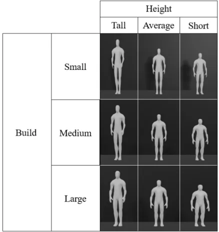
An important feature in the framework is the possibility to adapt the intended level of detail, ranging from geometry without materials or textures and minimal animation, to full scenes hav-ing as much detail as possible, includhav-ing materials, textures, complex animations or even adapted characteristics such as a person’s height and build. Figure3.2exemplifies the process for the se-lection of a template and its adaptation. If a description was to include a person, one could then increase the detail by defining this person’s height or build. Given the large range of possibilities
3.3 Framework Architecture 13
for these two parameters and to simplify the generation of the scenes, each was given three pos-sible levels; short, average or tall, concerning to height, and small, medium or large, to describe the build. These details and their levels can be combined to produce different results and better describe the people present in a scene. The original person template represents the combination of medium build and average height and all other combinations stem from it. Furthermore, it is possible to define a person’s skin tone and clothing to improve the detail in the generated scene.
Figure 3.2: Representation of the possible combinations of height and build in the model of a human.
3.3
Framework Architecture
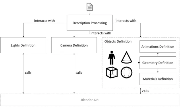
One of the goals during development was to ensure all functionalities could work as inde-pendent from each other as possible, having them defined as modules. The framework starts by processing the description of the scene to be represented. This parsed information is then used to generate lights, cameras and objects in the virtual environment, as represented in Figure3.3.
The Description processing module has a description file as input and interacts with all other modules based on the description’s content. The remaining modules define different parts of the
14 Scene Synthesis Framework
Figure 3.3: Schematic representation of the interaction between modules.
are completely independent from each other and only require the information provided by the Description Processing module. To allow the visualization of the contents of the scene, the Lights Definition module is crucial as light sources allow the distinction of objects and people. When users want to automatically render an image or video with the scene content, the camera definition module is pivotal as the camera defines the rendering point of view. Furthermore, to represent the content of the scene, another module was created to be responsible for all aspects relating to the people and objects on the scene. With the exception of the Description Processing module, all other modules regularly interact with Blender, through its API, to make the definitions and changes in the scene and its objects.
3.4
Scene Description
Even though the description language can be positioned outside the scope of this dissertation, a simple version of it was defined to allow the demonstration of the flow of the framework. The description language defined uses the JavaScript Object Notation (JSON) format.
Listing3.1represents the root object in the description. This object contains most aspects of the scene. As can be seen, the description has a clear distinction between three main groups: lights, cameras and objects. These match the modules defined and their contents are to be described in the coming paragraphs. However, two more fields are defined in the description’s root, these are the duration of the scene and the level of detail. The former is an integer representing the number of frames between the beginning of the scene (frame 1) and its end (frame 1 + duration). The
3.4 Scene Description 15
latter represents the level of detail the user intends to see in the resulting scene and influences the Objects Definition module thus its effects will be detailed in section4.5.
Listing 3.1: Structure of the description’s root object.
1 { 2 "lights": [ Light ], 3 "cameras": [ Transformations ], 4 "objects": [ Object ], 5 "duration": Integer, 6 "detail": 0 / 1 / 2 7 }
In Listing3.2the Light class containing all information for each light in the scene is detailed. Its fields correspond to the parameters needed to define a light, which will be more detailed in section4.3.
Listing 3.2: Structure of the scene lights’ description.
1 {
2 "color": [Float, Float, Float],
3 "type": "POINT" / "SPOT" / "AREA" / "SUN"
4 "power": Float,
5 "radius": Float (optional),
6 "angle": Float (optional),
7 "blend": Float (optional),
8 "size": Float (optional),
9 "size_y": Float (optional),
10 "shape": "RECTANGLE"/"SQUARE"/"ELLIPSE"/"DISK" (optional),
11 "transformations": [ Transformation ]
12 }
Transformations are applied to each light to allow placing it in the 3D scene. This is achieved using the transformations field that consists of a list of objects of the class Transformation, represented in Listing3.3. This class is used throughout the description to define position, rotation or scale. Values are always set as a vector having its positions correspond to the x, y and z axes. The type of transformation distinguishes between three possible transformations and between those being absolute or relative. This means that using types "position", "size", "rotation" sets the absolute value of these transformations in the scene object and the remaining possible types translate, rotate or scale the object based on its current corresponding values for location, size and rotation.
Listing 3.4 represents the Object class used to define all the information required to create objects. Each of the fields details different aspects relevant to the objects’ creation. The name field defines the name of the scene object created in Blender and serves as a key to identify the
16 Scene Synthesis Framework
Listing 3.3: Structure of the transformations’ description.
1 Transformation: {
2 "type": "position" / "translate" / "size" / "scale" / " rotation" / "rotate"
3 "vector": [Float, Float, Float]
4 }
The template is a field that can be an empty string to make this object an empty object, the name of a primitive shape – plane, cube, circle, sphere, cylinder, cone or grid – or the name of an FBX file to be imported. The children field is a list of objects with a similar structure being treated by Blender as being hierarchically related to the parent object, having its transformations and animations.
Listing 3.4: Structure of the scene objects’ description.
1 {
2 "name": String,
3 "template": String
4 "details": [ ObjectDetails ] (optional),
5 "materials": [ Material ], 6 "transformations": [ Transformation ], 7 "animations": [ Animation ], 8 "children": [ Object ], 9 "collisions": Collision 10 }
The details field is a list of objects with the structure defined in Listing 3.5. This defines, for imported objects, their stature and build. As a simplification each of the types has three possible values, for height those are: short, average and tall; for weight they are: small, medium and large.
Listing 3.5: Structure of the scene objects’ details’ description.
1 {
2 "type": "height" / "weight",
3 "value": "short" / "average" / "tall" / "small" / "medium" /
"large"
4 }
In the materials field, the materials for the object are defined with the fields shown in Listing3.6. Similarly to objects, a name is attributed to the material to be used internally in Blender. It is also possible to indicate the name of a texture or the hexadecimal code of colors to apply to the object. The vert_group refers to the vertex group to apply this material to. Vertex groups are defined in another JSON file containing lists of vertex indexes for the vertices belonging to the respective group.
3.4 Scene Description 17
Listing 3.6: Structure of the scene objects’ materials’ description.
1 {
2 "name": String,
3 "texture": String,
4 "colors": [ String ],
5 "vert_group": [ String ],
6 "mode": "stretch" / "repeat" (optional)
7 }
Animations are defined for each object as shown in Listing3.7. They require the definition of its initial and final frames. It also allows the definition of object transformations to be applied over time during this animation. The remaining fields, template and variant, relate to the possibility of defining an animation template with different variations, for instance, this allows the walking movement to be different for each person.
Listing 3.7: Structure of the scene objects’ animation’s description.
1 { 2 "frame_start": Integer, 3 "frame_end": Integer, 4 "transformations": [ Transformation ], 5 "template": String, 6 "variant": String 7 }
The last field in the object’s definition is collisions, shown in Listing 3.8. The animated field defines if the object should follow its animation or be affected by physics in case it is set to true or false, respectively. The fix_to field sets an anchor for the object, for instance, if one was to represent an object in a moving car, the object does not require animation as it can be anchored to the car thus, it follows the movement as supposed.
Listing 3.8: Structure of the scene objects’ collisions description.
1 {
2 "animated": Boolean,
3 "fix_to": String
4 }
Once the description is processed, the framework moves on to generating the scene and its contents. ListingA.1, available in AppendixA, shows an example of a description representing
18 Scene Synthesis Framework
Chapter 4
Framework Implementation
This chapter details the process of implementation of the developed framework. Before devel-opment could start, it was necessary to select the tools that best fit the framework’s needs. This process is described in section4.1. Hereinafter, in the following sections, the modules composing the framework are detailed. Section4.6is a reflection on several aspects of the implementation.
4.1
Requirements Gathering
Towards developing this framework, different graphic and game engines were tested to allow an informed choice of the one that best suits the needed features. These include the ability to define, create and manipulate objects’ geometry, materials and animations without having to use a graphical interface; the capacity to process files containing 3D models and text; and the ability to produce the final result into an image, video or executable file, removing the need for specific software to view the results.
The tests performed on engines were directed at those mentioned in section 2.2. For the engines presented in Table2.1, it is a common factor that all of them can produce a final result that does not require a specific program to be viewed. The remaining necessary features were tested in each engine and all were able to meet these requirements even though some presented limitations that were not deterrent to their usage. Therefore, these engines were compared based on their ease of use, limitations imposed and online support – such as documentation and forums. As a result of this comparison, the most promising engines were Unity, Unreal Engine, CryEngine, Blender and Open3D. Unity, Unreal Engine and CryEngine all presented the same limitation: these three game engines are very dependent on their editors, posing a difficulty in importing 3D models which requires functions tied to their interface, preventing the import of 3D models after building a standalone executable file. This means that any templates to be used for a generated scene had to be compiled with the executable file, requiring the project to be compiled if one intended to introduce a different template. Even though this reduces the framework’s flexibility, it does not impede the usage of these game engines. Different solutions could be found for the different engines:
20 Framework Implementation
• Unity has add-ons capable of handling the runtime import, however, the free version only imports files of the extension .obj, which does not include an object’s animations or materi-als;
• Unreal Engine also has add-ons to solve this limitation, however, none of those are free; • CryEngine is open source, which means its code is public and its import functions could
be recreated to work during runtime – this possibility, however, would require extensive research and exploration of the engine’s code, which is not in the scope of this dissertation. Blender, however, did not present many limitations: it does not produce an executable file and all its functions are available to the user – when using the interface one can know the exact func-tion called by each opfunc-tion by reading the tooltip text. Being a graphics engine and having all its functions available to the user, Blender allows one to change an object’s geometry, define anima-tions and set materials and textures, and presents, based on these tests, no apparent limitaanima-tions. Lastly, Open3D is also a graphics engine that, similarly to Blender, presents no apparent limita-tions. However, when compared to Blender, it does not reach its level of support. Given Blender’s feature of mapping actions in the interface to functions and that Open3d does not have an editor, Open3D’s functions are not as easy to find. Furthermore, aside from the official documentation, it was more difficult to find online discussions and support for Open3D than it was for Blender. Thus, having tested these engines, Blender proved to be the most promising and adequate for the requirements set for this dissertation; closely followed by Open3D.
Tests were also done to evaluate the usability of the SMPL models. As described in section2.3, these are parametric models of naked humans, capable of representing different body shapes and poses. The tests focused on the compatibility with the possible engines and ease of use. SMPL models show compatibility with Unity, Autodesk Maya and Python 2.7 in a Linux environment. The Linux setup for the SMPL models revealed fruitless as software incompatibilities made these tests impossible. Therefore, the Unity version of SMPL was the only version successfully tested. The models presented the expected appearance but proved challenging to adapt. As previously described in section2.3, these models use 207 pose blend shapes [23]. Furthermore, the SMPL model in unity has 10 shape blend shapes and 414 pose blend shapes, totaling 424 parameters needed to adapt and animate a model. Taking into consideration the complex nature of these models, and keeping in mind the incremental nature of the development process, it became visible that the detail presented in these models would not compensate the effort required to produce the simplest result. Moreover, documentation regarding the interconnection between these parameters is scarce, forcing a great investment of time upon attempting to use these models. Therefore, even though not being excluded from being a possible future improvement to the presented framework, SMPL models were not used to guide an initial decision for the development’s direction and the choice of a tool.
Concerning the decision on the engine to use for development, the top contenders were Blender and Unity. The option of using the SMPL models to represent humans with greater detail made Unity a promising option despite its limitations to importing 3D models at runtime. However,
4.2 Description Processing 21
having reduced the necessity for the SMPL models, Unity’s promise reduces as well. Therefore, Blender was chosen as a development tool as it provided the best combination of functionality, ease of use and support.
4.2
Description Processing
The Description Processing module is responsible for reading and processing the scene’s de-scription and also sends to the remaining modules all the information relevant to their operation. Development for this module focused on the creation of the simple description language, previ-ously detailed in section3.4, and its translation into the virtual scene’s elements.
The process starts with the Description Processing module. It receives the file containing the scene’s description and parses it’s content into python data structures to be used in the ensuing modules.
4.3
Lights Definition
The Lights Definition module is responsible for defining four different types of lights along with their position in the 3D virtual world. These lights allow a user to view the content of the scene as they illuminate the defined geometry. Users can define as many lights as they require but must be aware of the different parameters that define the various light types, as detailed in Table4.1. Aside from these specific parameters, all lights require their position and color to be defined.
The creation of lights in Blender requires the iteration through all defined lights and, for each of them, the creation of a Light Object and a Scene Object. The Light Object is created with the parameters set in the description. The Scene Object is created with a sequential name and encapsulates the light and adds it to the 3D scene in its desired position and rotation. It is worth noting, no scale is ever applied to lights because, when tested, it had no practical effect on them.
Once all lights are defined and positioned in the scene, execution moves to the creation of the virtual camera.
4.4
Camera Definition
The Camera Definition module allows the definition of virtual cameras whose purpose is set-ting a point of view from which the scene is rendered into an image or video. Camera creation takes as input the transformations necessary to have the camera in the desired position. This isn’t a mandatory object when creating a scene but it is required if the user intends to render the scene into an image or an animated video, as it sets the point of view from which the content is rendered. Figure4.1exemplifies different points of view of the same scene. This example shows the impor-tance of the camera position as some objects in the scene are not visible from some of the points
22 Framework Implementation
Table 4.1: Details of different light types and required parameters for each, adapted from [24] Light
Type Description
Parameters
Name Description
Point A point radiating the same amount of light in all directions. Light intensity/energy decays based on (among other variables) distance from the Point light to the object
power Power of the light in Watts. Higher val-ues increase the intensity of the light. radius When larger than zero, light will be
emit-ted from a spherical surface with the specified radius. Larger radius creates softer shadows and specular highlights. Spot
Light is emitted as a
cone-shaped beam of light from the tip of the cone, in a given direction. A falloff rate can be calculated using the Blend and Size variables. This determines if the transition from the spot’s light to its surrounding shadows is sharper or softer.
power Power of the light in Watts. Higher val-ues increase the intensity of the light. radius When larger than zero, light will be
emitted from a spherical surface with the specified radius. Larger size creates softer shadows and specular highlights. size The size of the outer cone of a Spot. It
largely controls the circular area a Spot light covers, by affecting the angle at the top of the lighting cone, representing an angle between (1.0 to 180.0).
blend Blend controls the inner cone of the Spot. Its value can be between (0.0 to 1.0) and represents the amount of space the inner cone should occupy inside the outer cone Size.
Area
The Area light simulates light originating from a surface emitter, such as a TV screen, neon lights, a window, or a cloudy sky. It produces shadows with soft borders by sampling a light along a grid the size of which is defined by the user. This is in direct contrast to point-like artificial lights which produce sharp borders.
power Power of the light in Watts. Higher val-ues increase the intensity of the light. size-y /
size
Dimensions for the Square or Rectangle. shape Shape of the light, it can be a Rectan-gle, Square, Disk or Ellipse. Squares and Disks are a specific variation of Rectan-gles and Ellipses, respectively. The shape of the lights can be changed with the Size variables, either "X" and "Y" for Rectan-gles and Ellipses or just the Size property for Squares and Disks.
Sun Light is provided with constant intensity and emitted in a single direction from infinitely far away.
power Strength of the lights in Watts per square meter.
angle The size of the sun light according to its angular diameter as seen from earth.
Cameras are created in a similar fashion to lights, one must create a Camera Object and en-capsulate it with a Scene Object. This Scene Object is also named sequentially and is responsible for placing the camera in the desired position with the desired rotation. Also similarly to lights, cameras do not have any scale applied to them, in this case, its effects are only visible when a
4.5 Objects Definition 23
Figure 4.1: Example with different points of view for the same scene.
negative scale is applied, which results in an undesirable inversion of the view. Even though sev-eral cameras can be defined, in the current state of development, no support for multiple cameras was added upon rendering the scene and the last camera to be created is used as the camera for rendering.
4.5
Objects Definition
The module described in this section is responsible for defining all the objects that represent the scene’s content and convey the information represented in the scene.
To simplify the objects’ definition process, this module was further divided into three sub-modules each responsible for one aspect of the object – geometry, animation and materials. The Geometry Definition module is imperative to define the geometry of the objects. To allow the generation of animated scenes, the Animation Definition module is necessary. The Materials Definition module handles the visual aspect of the objects related to their colors and textures.
Furthermore, when an object is defined, it can only be defined as one of three options, it is either a primitive, an imported model or an empty object, each requiring a different approach in this module. An empty object is defined to be a parent of other objects and allows several objects to share geometric transformations, thus implementing a hierarchy and simplifying the description by allowing transformations and animations to be defined only once in the parent object.
Moreover, this module is affected by the desired level of detail defined in the description. There exist three possible levels of detail:
• The lowest level of detail has objects shown with their simplest possible appearance, which means objects are shown with a default material, simple animations based on geometric transformations – translation, rotation, scale – and their default geometry.
• The second level builds upon the previous and allows one material to be defined per ob-ject and complex animations without variations – a person can walk instead of sliding but everybody has the same walking movement.
• The third level of detail also allows different materials to be defined to different parts of the same object, the definition of details such as height and build and variants in complex
24 Framework Implementation
Figure4.2shows an example of the three levels of detail for a person described as being of large build and short height and wearing a white shirt with blue pants and white shoes. The possibility of representing different levels of detail is of great importance because it allows the reduction of the information in the description in cases where a lower level of detail is required.
Figure 4.2: Representation of the three possible levels of detail for a human model.
4.5.1 Geometry Definition
The module described in this section is responsible for the definition of all the scene objects’ geometry and location in the scene, as well as the hierarchic relations between scene objects. This sub-module is required by both Animation and Material Definition sub-modules. An empty object has no visual representation, ergo no geometry associated and, as such, only makes use of this sub-module to define its position in the 3D scene. Objects defined as primitives can be one of the following: cubes, two-dimensional circles, spheres, cylinders, cones or planes. These objects are defined using the engine’s primitives and can only represent basic geometric shapes. Imported models are objects created from a filmbox (FBX) file and can represent more complex geometry. These models also allow the definition of extra details such as the height and build. The change of height in the model is achieved by scaling along the vertical axis. The adaptation of the build is achieved by scaling the model along its normals and also, along both horizontal axes. For these types of objects, this sub-module is responsible for importing them as well as adapting them to any defined detail.
Furthermore, this sub-module is responsible for defining if an object is affected by physics or its animation. This makes use of Blender’s rigidbody system and defines all objects as rigid bodies, setting their properties according to the description. This is an important aspect in the
4.5 Objects Definition 25
creation of a scene as it can help balance the described scene with what is expected in a real-life scenario thus imposing a certain level of realism to any generated scene.
4.5.2 Animation Definition
The present section details the module capable of defining animations of two kinds, simple an-imations based on geometric transformations – translation, rotation and scale – and more complex transformations applied to armatures associated with imported models, working as a skeleton and changing the model’s mesh. In Figure4.3it is possible to see the original mesh on the left and its respective armature in the middle. The model on the right includes both mesh and armature in a pose defined through the latter.
Figure 4.3: Example of an armature and its application to a human body.
Simple Animations can be applied to all object types. They are based on geometric transfor-mations, such as translation, rotation and scale, prolonged throughout a certain amount of frames, as defined in the description.
Complex Animations are only compatible with imported objects that have an armature defined. These animations also require their own description including the transformations to apply to each bone throughout the respective frames, as represented in Listing4.1. This definition allows one to set how an animation starts, how it ends and what should happen in between. For instance, a walking animation should start in a standing position before one of the feet is moved forward; then, the feet are repeatedly alternated moving forward; and in the end, the last step is not taken forward but to have both feet side by side. To have results apparently more natural, it was also made possible that animations are symmetric, this means that an animation is always defined for
26 Framework Implementation
symmetric. For example, the walking animation could start with the left foot or with the right and proceed to alternate between those during the animation.
Listing 4.1: Structure of the scene objects’ animation’s description.
1 {
2 "name": String,
3 "keyframes": [
4 {
5 "duration": Integer,
6 "mode": "start" / "repeat" / "end",
7 "keys": [ 8 { 9 "frame": Integer, 10 "bone": String, 11 "clone": String, 12 "transformations": [ Transformation ] 13 } 14 ] 15 } 16 ] 17 }
Therefore, the inclusion of these animations defined by an armature allows for a greater level of detail and helps convey the information represented in the scene.
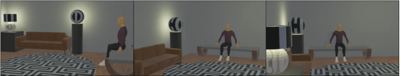
Having Simple and Complex Animations combined can generate powerful results such as the appearance of a person more naturally moving in the world, as represented in Figure4.4. It also makes possible the creation of animations to interact with the surrounding world.
4.5.3 Material Definition
This section describes the module responsible for defining materials capable of having textures and applying them to objects in the scene. Having no visual representation, empty objects do not require this module to be used.
The Material Definition module allows users to set an object’s color or apply a preexisting texture to it. The developed framework receives the information in the description and creates a matching material. Textures are, by default, repeated to cover the whole mesh. However, it is possible to change its mode to be stretched to cover the mesh. Furthermore, it is also possible to define different materials for specific parts of an imported model, only requiring the existence of a link between keywords and specific groups of the model’s vertices. This is done using a descrip-tion file that includes lists of vertex indexes for the vertices belonging to each group. With this functionality, it also becomes possible to represent a person’s skin tone and clothing by coloring
4.6 Discussion 27
Figure 4.4: Example of the combination of Simple and Complex animations to represent the walking movement.
the areas that correspond to skin and clothing pieces with a user-defined color. Figure4.5shows the possibilities of this functionality. Both people in the figure were first given a skin color ap-plied to the whole mesh. Then, for individual pieces of clothing, the corresponding vertices were selected and given the described material.
4.6
Discussion
Overall, requirements gathering was a satisfactory process and resulted in the choice of soft-ware that allowed the development of the framework. Nevertheless, during the development phase, several problems were encountered and had to be overcome. At the beginning of the development of the framework, the Blender engine presented some obstacles as some functions were condi-tioned by the mouse cursor position. This became an issue because most functions are called before the engine window opens and, having many areas available in the context, Blender had difficulties identifying the context in which the functions were called. The solution to this was re-moving from Blender’s window, all areas that were not necessary during the script’s run and reset-ting the window’s areas just before the script ended. This solution fixed all context-related issues. Another issue found during development was that when applying a scale along a mesh’s normals the mesh lost its scaling. To solve this issue, the object’s scale had to be saved and re-applied to the mesh after the scale along its normals. Realism was also a difficulty found in specific aspects as the definition of the objects’ positions could produce some overlapping results. The solution found to this problem was using Blender’s physics system and defining collisions between objects. This
28 Framework Implementation
Figure 4.5: Example of the usage of materials to represent different people’s skin tones and cloth-ing colors.
Chapter 5
Experiments and Results
Once the framework was capable of producing satisfactory results, it was necessary to assess its quality and usability. To accomplish this, two main tests were performed. The first was the comparison of the time necessary to create a 3D scene by hand and the time taken by the framework to generate a similar scene. The second test performed aimed at evaluating the perception of users on the generated content to evaluate the quality of the results.
5.1
Scene Generation
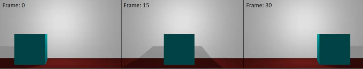
With the developed framework several different scenes can be represented with varying levels of detail. Figure5.1 demonstrates the result of representing the content of the same description in 3D scenes with varying levels of detail. As can be seen, the lowest level of detail represents all geometry with a default material. The average and high levels of detail include materials and present very similar results. The only difference in these two scenes is the clothing on the person as the second level of detail only represents the first material defined, in this case, the skin tone. However, some differences are more noticeable when representing an animated scene. Figure5.2 demonstrates the effect that different levels of detail have on animations. To simplify interpretation, this scene was defined as a person walking in a simple environment. As can be seen, all levels of detail include some level of animation. The lowest level of detail represents animations as simple geometric transformations, in this case, it is possible to see the person slid from one side to the other. Similarly to the static scene, differences between the two higher levels of detail are
30 Experiments and Results
Figure 5.2: Results obtained for the same animation with three levels of detail.
more discreet. In the case of animation, both levels represent complex animations. However, as can be seen in the images, the animations present some differences. In the second level of detail animations don’t have any variations, in this case, every person with a walking animation would walk the exact same way. However, in the third level of detail, different variations of animations are allowed. This can be seen in the images by analyzing the differences between the two levels of detail in the same frames.
5.2
Experiments
Having as one of the main goals the reduction of the time necessary to create a 3D scene, it is important to compare the time taken creating a scene by hand and the time needed to generate it automatically. The objective of this experiment is to have many people, with varying degrees of experience, creating 3D scenes. They have to be given the same 3D scene to create and the time taken by each person is recorded. Those results can then be compared to the time taken to generate the same scene with the developed framework. However, due to unforeseen restrictions, only one scene was created by hand and serves as the term of comparison. The volunteer didn’t have much experience creating 3D scenes but demonstrated an interest in the subject stemming from video games, furthermore, this person was more comfortable using the Unity Game Engine [8] than Blender and, therefore, it was the engine used to create the scene by hand.
The scene to be represented was a simple depiction of a shopping center. It was to have esca-lators, stores, people, benches and minimalist decoration. In the end, the automatically generated scene is as represented in Figure5.3and the scene made by hand is represented in Figure5.4. Due to the usage of distinct engines, there are differences between the results that are inherent to the difference in software. As a result, the scene created by hand includes a tree generated by Unity, specific 3D models for people – including the hair and clothing – and the stores that are Unity assets. As it wasn’t possible to use these models in the developed framework, some alternatives
5.2 Experiments 31
Figure 5.3: Shopping Center scene generated automatically.
had to be arranged. Despite some differences in lighting and some details, the results are quite close and convey similar information.
Table 5.1: Necessary time to import models for the generated scene.
model amount time
average total person 4 0.605s 2.422s escalator 2 0.148s 0.297s bench 8 0.262s 2.094s tree 1 1.609s 1.609s Total: 6.422s
The time necessary to search and select the most adequate assets was similar for both cases as most of the assets were the same. The time taken to create the scene by hand was recorded at 7 hours and 40 minutes. The automatic generation of the scene took 10.267 seconds. The resulting scene shows a clear improvement from the scene created by hand. The process of generating the scene is heavily influenced by its complexity and some parts of the framework can have a greater impact than others. As can be seen in Table5.1, 6.422 seconds of the 10.267 seconds needed to generate the scene were spent on importing models. The remainder of the time, 3.845 seconds, is used by Blender to create the lights, camera, primitives, materials and animations as well as
![Figure 2.1: Example of image-based reconstruction adapted from [18].](https://thumb-eu.123doks.com/thumbv2/123dok_br/15595025.1051169/27.892.150.787.584.988/figure-example-image-based-reconstruction-adapted.webp)
![Figure 2.2: Example of a 3D laser scan of a real-world environment adapted from [17].](https://thumb-eu.123doks.com/thumbv2/123dok_br/15595025.1051169/28.892.105.747.147.561/figure-example-laser-scan-real-world-environment-adapted.webp)
![Figure 2.3: Exemplification of an SMPL Model from [23].](https://thumb-eu.123doks.com/thumbv2/123dok_br/15595025.1051169/29.892.160.781.390.553/figure-exemplification-smpl-model.webp)

![Table 4.1: Details of different light types and required parameters for each, adapted from [24]](https://thumb-eu.123doks.com/thumbv2/123dok_br/15595025.1051169/42.892.129.749.171.1008/table-details-different-light-types-required-parameters-adapted.webp)