Protocols
Nuno Neves
Paulo Verissimo (editors)
DI–FCUL
TR–08–3
January 2008
Departamento de Inform´atica
Faculdade de Ciˆencias da Universidade de Lisboa
Campo Grande, 1749–016 Lisboa
Portugal
Technical reports are available at http://www.di.fc.ul.pt/tech-reports. The files are stored in PDF, with the report number as filename. Alternatively, reports are available by post from the above address.
Project Acronym:
CRUTIAL
Start date of the project:
01/01/2006
Duration: 36 months
Deliverable no.:
D10
Title of the deliverable: Preliminary Specification of
Services and Protocols
Project co-funded by the European Commission within the Sixth
Frame-work Programme (2002-2006)
Contractual Date of Delivery to the CEC: 17/01/2008
Actual Date of Delivery to the CEC: 17/01/2008
Organisation name of lead contractor for this deliverable FCUL Editor(s): Nuno Neves2, Paulo Verissimo2
Author(s): Anas Abou El Kalan4; Amine Baina4; Hakem Beitollahi5; Alysson Bessani2; Andrea Bondavalli3: Miguel Correia2; Alessandro Daidone3; Geert Deconinck5; Yves Deswarte4; Fabrizio Garrone1;Fabrizio Grandoni3; Henrique Moniz2; Nuno Neves2; Tom Rigole5; Paulo Sousa2; Paulo Verissimo2
Participant(s): (1) CESI-R; (2) FCUL; (3) CNR-ISTI; (4) LAAS-CNRS; (5) KUL; (6) CNIT
Work package contributing to the deliverable: WP4
Nature: R
Dissemination level: PU
Version: 004
This document describes the preliminary specification of services and protocols for the Crutial Architecture. The Crutial Architecture definition, first addressed in Crutial Project Tech-nical Report D4 (January 2007), intends to reply to a grand challenge of computer science and control engineering: how to achieve resilience of critical information infrastructures, in particular in the electrical sector.
The definitions herein elaborate on the major architectural options and components es-tablished in the Preliminary Architecture Specification (D4), with special relevance to the Crutial middleware building blocks, and are based on the fault, synchrony and topological models defined in the same document. The document, in general lines, describes the Runtime Support Services and APIs, and the Middleware Services and APIs. Then, it delves into the protocols, describing: Runtime Support Protocols, and Middleware Services Protocols.
The Runtime Support Services and APIs chapter features as a main component, the Proactive-Reactive Recovery Service, whose aim is to guarantee perpetual execution of any components it protects.
The Middleware Services and APIs chapter describes our approach to intrusion-tolerant middleware. The middleware comprises several layers. The Multipoint Network layer is the low-est layer of CRUTIAL’s middleware, and features an abstraction of basic communication services, such as provided by standard protocols, like IP, IPsec, UDP, TCP and SSL/TLS. The Communica-tion Support Services feature two important building blocks: the Randomized Intrusion-Tolerant Services (RITAS), and the Overlay Protection Layer (OPL) against DoS attacks. The Activity Support Services currently defined comprise the CIS Protection service, and the Access Control and Authorization service. Protection as described in this report is implemented by mechanisms and protocols residing on a device called Crutial Information Switch (CIS). The Access Control and Authorization service is implemented through PolyOrBAC, which defines the rules for in-formation exchange and collaboration between sub-modules of the architecture, corresponding in fact to different facilities of the CII’s organizations.The Monitoring and Failure Detection layer contains a preliminary definition of the middleware services devoted to monitoring and failure detection activities.
The remaining chapters describe the protocols implementing the above-mentioned ser-vices: Runtime Support Protocols, and Middleware Services Protocols.
Table of Contents 1
List of Figures 2
1 Introduction 5
2 Runtime Support Services and APIs 8
2.1 Proactive-Reactive Recovery Service . . . 8
2.1.1 Overview . . . 8
2.1.2 Model of the System . . . 9
2.1.3 Service Description and Interface . . . 10
3 Middleware Services and APIs 14 3.1 Multipoint Network . . . 14
3.1.1 Internet Protocol . . . 14
3.1.2 Internet Protocol Security . . . 15
3.1.3 User Datagram Protocol and Transmission Control Protocol . . . 16
3.1.4 Secure Socket Layer . . . 18
3.2 Communication Support Services . . . 19
3.2.1 Randomized Intrusion-Tolerant Services . . . 19
3.2.2 Overlay Protection Against Denial-of-Service Attacks . . . 23
3.3 Activity Support Services . . . 37
3.3.1 CIS Protection Service . . . 37
3.3.2 Access Control and Authorization Service . . . 40
3.4 Monitoring and Failure Detection . . . 48
3.4.1 Diagnosis Framework . . . 48
3.4.2 Diagnosis in CRUTIAL . . . 49
4.1 Proactive-Reactive Recovery Protocols . . . 53
4.1.1 System Model . . . 53
4.1.2 The Protocols . . . 53
5 Middleware Services Protocols 57 5.1 Multipoint Network . . . 57
5.2 Communication Support . . . 59
5.2.1 Randomized Intrusion-Tolerant Protocols . . . 59
5.2.2 Overlay Network Protocols . . . 71
5.3 Activity Support Protocols . . . 78
5.3.1 CIS Protection Protocol . . . 78
5.3.2 Access Control and Authorization Protocols . . . 87
5.4 Monitoring and Failure Detection . . . 99
5.4.1 Design Rationale . . . 99
5.4.2 Services Specification . . . 100
5.4.3 Diagnosing the Protection Service . . . 102
5.4.4 Advantages and Limits of the PRRW Strategy . . . 109
5.4.5 Direction for Improvements/Refinements . . . 110 5.4.6 Architectural Modifications for the Detection of the Extended Set of Fault 112
6 Conclusions 114
1.1 CRUTIAL middleware. . . 6
2.1 Relationship between the rejuvenation period TP, the rejuvenation execution time TD, and k. . . 11
2.2 PRRW architecture. . . 11
2.3 Recovery schedule (in an Si j or Risubslot there can be at most k parallel replica recoveries). . . 13
3.1 Countermeasure techniques against DoS attacks. . . 25
3.2 Rate control mechanism from high level view [41]. . . 27
3.3 SoS architecture [54]. . . 28
3.4 The OPL architecture. . . 29
3.5 Threat against the OPL architecture. . . 33
3.6 DoS attack in the static case. . . 33
3.7 DoS attack in the dynamic case. . . 34
3.8 DDoS attack in the dynamic case. . . 34
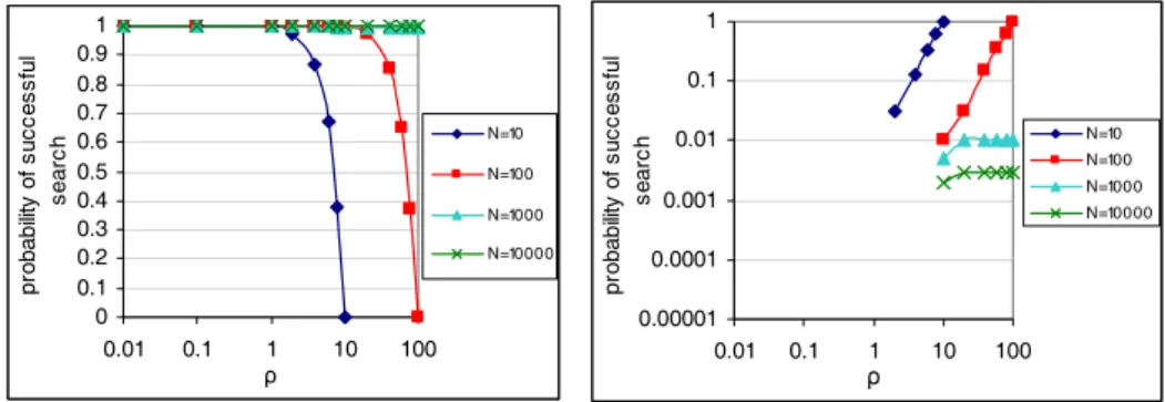
3.9 Impact of node joining/leaving for a) DoS and b) DDoS attacks. (X-axis: ρ; Y-axis: percentage of absent nodes; Z-Y-axis: probability of a successful search) . . . 35
3.10 Impact of the number of green nodes per application on the OPL performance. . . 36
3.11 Delay of the overlay network. . . 36
3.12 WAN-of-LANs connected by CIS. . . 38
3.13 The general functionning. . . 41
3.14 Scenario 1 exchanged commands. . . 42
3.15 Scenario 2 exchanged commands. . . 44
3.16 Scenario 3 exchanged commands. . . 46
3.17 Scenario 4 exchanged commands. . . 47
5.1 The RITAS protocol stack. . . 59
5.2 Flooding search in Type I protocols. . . 71
5.3 Chord routing algorithm. . . 72 3
5.4 Routing algorithm in Napster. . . 73
5.5 Hybrid decentralized indexing. . . 73
5.6 Intrusion-tolerant CIS architecture. . . 80
5.7 Scenario 1 users and services. . . 88
5.8 Scenario 2 users and services. . . 90
5.9 Arming Web Service Sequence Diagram. . . 94
5.10 Scenario 3 users and services. . . 95
5.11 Scenario 4 users and services. . . 96
5.12 Teleoperation Web Service Sequence Diagram. . . 98
5.13 System failure probability PF(t) over mission time t for different values of pI. . . 105
5.14 System unavailability PU(t) over mission time t for different values of pI. . . 106
5.15 Impact of detection coverage cMon failure probability PFI(t) due to invalid behav-ior for different values of pI. . . 107
5.16 Impact of detection coverage cM on failure probability PFO(t) due to omissive behavior for different values of pI. . . 107
5.17 Impact of detection coverage cM on system failure probability PF(t) for different values of pI. . . 107
5.18 Impact of detection coverage cM on system unavailability PU(t) for different val-ues of pI. . . 108
5.19 System failure probability PF(t) for different system configurations at mission time t=2628. . . 109
5.20 System unavailability PU(t) for different system configurations at mission time t=2628. . . 109
1
Introduction
This document describes the preliminary specification of services and protocols for the Crutial Architecture. The Crutial Architecture definition, first addressed in Crutial Project Tech-nical Report D4 (January 2007), intends to reply to a grand challenge of computer science and control engineering: how to achieve resilience of critical information infrastructures, in particular in the electrical sector.
The scope considered spans the threats against computers and control computers, not the physical infrastructures themselves. The focus are systems with great socio-economic value, such as utility systems like electrical, gas or water, or telecommunication systems.
In the above-mentioned report, we laid down the basis for our work, whose final objectives are:
• Ensuring acceptable levels of service and, in last resort, the integrity of systems themselves, when faced with threats of several kinds. Doing so in an automatic and adaptive way. • Taking into account the hybrid composition of those infrastructures: operational network,
called generically SCADA, devoted to the physical processes; corporate intranet, where usual departmental services and clients reside; Internet, through which intranet users get to other intranets and/or the outside world; interconnections between all of these, including SCADA-Internet.
Intrusion tolerance, a workhorse of the Crutial approach, advocates the use of redundancy to ensure that a system still delivers its service correctly even if some of its components are com-promised. Typical protocols, said of ’Byzantine resilience’, or ’Byzantine fault tolerance’, only operate correctly if at most a specified number f out of the n available replicas are compromised. However, given a sufficient amount of time, a malicious and intelligent adversary can find ways to compromise more than f replicas and collapse the whole system. The problem can be minimized if the replicas are rejuvenated periodically, using a technique called proactive recovery, to remove the effects of malicious attacks/faults. In fact, if the rejuvenation is performed sufficiently often, then an attacker is never able to corrupt enough replicas to break the system, and the latter operates perpetually. These paradigms outline the background of the approach of Crutial to resilience.
In this document, we present a preliminary specification of services and protocols of the Crutial Architecture. The definitions herein elaborate on the major architectural options and com-ponents established in the Preliminary Architecture Specification (D4), with special relevance to the CRUTIAL middleware building blocks, and are based on the fault, synchrony and topological models defined in the same document. The document, in general lines, describes the Runtime Sup-port Services and APIs, and the Middleware Services and APIs. Then, it delves into the protocols, describing: Runtime Support Protocols, and Middleware Services Protocols.
The Runtime Support Services and APIs chapter features as a main component, the Proactive-Reactive Recovery Service, whose aim is to guarantee perpetual execution of any components it protects.
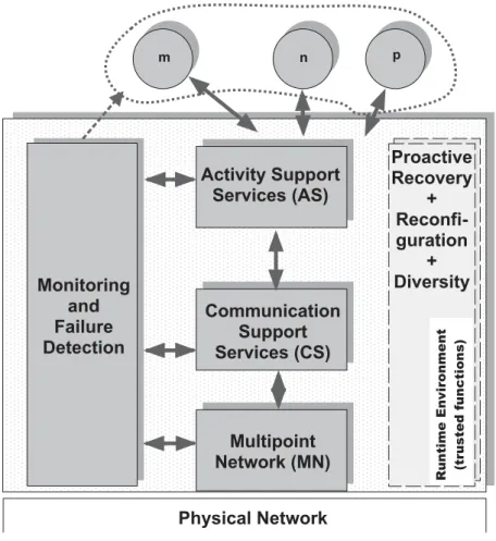
M o n i t o r i n g a n d F a i l u r e D e t e c t i o n P h y s i c a l N e t w o r k M u l t i p o i n t N e t w o r k ( M N ) n m p C o m m u n i c a t i o n S u p p o r t S e r v i c e s ( C S ) A c t i v i t y S u p p o r t S e r v i c e s ( A S ) P r o a c t i v e R e c o v e r y + R e c o n f i -g u r a t i o n + D i v e r s i t y R u n ti m e E n vi ro n m e n t (t ru st e d f u n c ti o n s)
Figure 1.1: CRUTIAL middleware.
In Crutial we investigated limitations of existing approaches to intrusion-tolerant proactive recovery, and proposed a very complete scheme addressing them, which we named proactive-reactive recovery. Our first observation is that protecting oneself from timing attacks by using asynchronous models, and fulfilling periodic recoveries, are incompatible goals. To address this issue, we propose an innovative scheme based on a hybrid sync-asynchronous architecture, called proactive resilience. Our second observation is that one should allow correct replicas that detect or suspect that some replica is faulty, to accelerate the recovery of this replica. It is known that perfect Byzantine failure detection is impossible to attain in a general way. In consequence, dealing with imperfect failure detection is the most complex aspect of the proactive-reactive recovery service presented.
The Middleware Services and APIs chapter describes our approach to intrusion-tolerant middleware (see Figure 1.1). The middleware comprises several layers.
The Multipoint Network layer is the lowest layer of CRUTIAL’s middleware, and features an abstraction of basic communication services, such as provided by standard protocols, like IP, IPsec, UDP, TCP and SSL/TLS.
The Communication Support Services feature two important building blocks: the Random-ized Intrusion-Tolerant Services (RITAS), and the Overlay Protection Layer (OPL) against DoS attacks. The Randomized Intrusion-Tolerant Services (RITAS) are organised as a stack of
ran-domized intrusion-tolerant protocols, supporting applications who depend on intrusion-tolerant broadcast and agreement. These protocols, being randomized, overcome the impossibility result in asynchronous settings established in [38] (also called the FLP result), but present a significant performance improvement over previous protocols of the same class. In recent years DoS attacks have become one of the most serious security threats to the Internet. Today Internet protocols have become an emerging technology for remote control of industrial applications, and as such, vulnerable to the same kind of attacks. We address an overlay protection layer for DoS attacks on top of the normal infrastructure, for solving DoS Problem.
The Activity Support Services currently defined comprise the CIS Protection service, and the Access Control and Authorization service.
The CRUTIAL reference architecture models the whole infrastructure architecture as a WAN-of-LANs. This topology allows simple solutions to hard problems such as legacy control subnetworks, and interconnection of critical and non-critical traffic, by defining realms with dif-ferent levels of trustworthiness. The CIS Protection service protects realms from one another, i.e., a LAN from another LAN or from the WAN, thus allowing us to deal both with outsider and in-sider threats. Protection as described in this report is implemented by mechanisms and protocols residing on a device called CRUTIAL Information Switch (CIS).
The Access Control and Authorization service is implemented through PolyOrBAC, which defines the rules for information exchange and collaboration between sub-modules of the architec-ture, corresponding in fact to different facilities of the Critical Information Infrastructures (CII). Each organization specifies its security policy according to OrBAC. As organizations are inter-connected through CIS, each CIS regroups mechanisms to define security policy of systems that compose each LAN (local and collaboration policies), and it also regroups mechanisms for col-laboration: to make these LANs capable of collaboration and offering services to each other.
The Monitoring and Failure Detection section contains a preliminary definition of the middleware services devoted to monitoring and failure detection activities. Diagnosis in Cru-tial should occur at different components at different architectural levels, and as such, the classical framework has been extended: several components need to be monitored and several deviation detection mechanisms need to be in place, errors observed in different components must be corre-lated. Likewise, given that we are dealing with a complex infrastructure, methods for distributed diagnosis are mandatory, with a distinction between local and global detection and diagnosis.
The remaining chapters describe the protocols implementing the above-mentioned ser-vices: Runtime Support Protocols, and Middleware Services Protocols.
2
Runtime Support Services and APIs
2.1
Proactive-Reactive Recovery Service
This section describes the proactive-reactive recovery service and its interface. The proto-cols used to implement this service are presented in Section 4.1. Before describing the proactive-reactive recovery service, we start by motivating the necessity of such a service, and by explaining the system model in which the proactive-reactive recovery service is based.
2.1.1 Overview
One of the most challenging requirements of distributed systems being developed nowa-days is to ensure that they operate correctly despite the occurrence of accidental and malicious faults (including security attacks and intrusions). In the context of CRUTIAL, this problem is specially relevant for an important class of systems that are employed in mission-critical applica-tions such as the SCADA systems used to manage critical infrastructures like the Power grid. One approach that promises to satisfy this requirement and that gained momentum recently is intru-sion tolerance[90]. This approach recognizes the difficulty in building a completely reliable and secure system and advocates the use of redundancy to ensure that a system still delivers its service correctly even if some of its components are compromised.
A problem with “classical” intrusion-tolerant solutions based on Byzantine fault-tolerant replication algorithms is the assumption that the system operates correctly only if at most f out of nof its replicas are compromised. The problem here is that given a sufficient amount of time, a malicious and intelligent adversary can find ways to compromise more than f replicas and collapse the whole system.
Recently, some works showed that this problem can be solved (or at least minimized) if the replicas are rejuvenated periodically, using a technique called proactive recovery [69]. These previous works propose intrusion-tolerant replicated systems that are resilient to any number of faults [17, 101, 15, 61, 80]. The idea is simple: replicas are periodically rejuvenated to remove the effects of malicious attacks/faults. Rejuvenation procedures may change the cryptographic keys and/or load a clean version of the operating system. If the rejuvenation is performed sufficiently often, then an attacker is unable to corrupt enough replicas to break the system. Therefore, us-ing proactive recovery, one can increase the resilience of any intrusion-tolerant replicated system able to tolerate up to f faults/intrusions: an unbounded number of intrusions may occur during its lifetime, as long as no more than f occur between rejuvenations. Both the interval between consecutive rejuvenations and f must be specified at system deployment time according to the expected rate of fault production.
An inherent limitation of proactive recovery is that a malicious replica can execute any action to disturb the system’s normal operation (e.g., flood the network with arbitrary packets) and there is little or nothing that a correct replica (that detects this abnormal behavior) can do
to stop/recover the faulty replica. Our observation is that a more complete solution should allow correct replicas that detect or suspect that some replica is faulty to accelerate the recovery of this replica. We named this solution as proactive-reactive recovery and claim that it may improve the overall performance of a system under attack by reducing the amount of time a malicious replica has to disturb system normal operation without sacrificing periodic rejuvenation, which ensures that even dormant faults will be removed from the system. The key property of our approach is that, as long as the fault exhibited by a replica is detectable, this replica will be recovered as soon as possible, ensuring that there is always an amount of system replicas available to sustain system’s correct operation.
We recognize that perfect Byzantine failure detection is impossible to attain in a general way, since what characterizes a malicious behavior is dependent on the application semantics [32, 31, 7, 45]. However, we argue that an important class of malicious faults can be detected, specially the ones generated automatically by malicious programs such as virus, worms, and even botnets. These kinds of attacks have little or no intelligence to avoid being detected by replicas carefully monitoring the environment. However, given the imprecisions of the environment, some behaviors can be interpreted as faults, while in fact they are only effects of overloaded replicas. In this way, a reactive recovery strategy must address the problem of (possible wrong) suspicions to ensure that recoveries are scheduled according to some fair policy in such a way that there is always a sufficient number of replicas for the system to be available. In fact, dealing with imperfect failure detection is the most complex aspect of the proactive-reactive recovery service presented in this section.
2.1.2 Model of the System
Recently, it was shown that proactive recovery can only be implemented with a few syn-chrony assumptions [81, 82]: in short, in an asynchronous system a compromised replica can delay its recovery (e.g., by making its local clock slower) for a sufficient amount of time to allow more than f replicas to be attacked. To overcome this fundamental problem, the proactive-reactive recovery service is based on a hybrid system model [89] in which the system is composed of two parts, with distinct properties and assumptions, let us call them payload and wormhole.
Payload. Any-synchrony system with n ≥ a f + bk + 1 replicas P1, ..., Pn. This part can range from
fully asynchronous to fully synchronous. At most f replicas can be subject to Byzantine failures in a given recovery period and at most k replicas can be recovered at the same time. The exact threshold depends on the application. For example, an asynchronous Byzantine fault-tolerant state machine replication system requires n ≥ 3 f + 2k + 1 while the CIS Protection Service presented in Section 3.3.1 requires only n ≥ 2 f + k + 1. If a replica does not fail between two recoveries it is said to be correct, otherwise it is said to be faulty. We assume fault-independence for payload replicas, i.e., the probability of a replica being faulty is independent of the occurrence of faults in other replicas. This assumption can be substantiated in practice through the extensive use of several kinds of diversity [68].
can fail by crash. These local wormholes are connected through a synchronous and secure control channel, isolated from other networks. There is one local wormhole per payload replica and we assume that when a local wormhole i crashes, the corresponding payload replica i crashes together. Since the local wormholes are synchronous and the control channel used by them is isolated and synchronous too, we assume several services in this environment:
1. wormhole clocks have a known precision, obtained by a clock synchronization protocol; 2. there is point-to-point timed reliable communication between every pair of local wormholes; 3. there is a timed reliable broadcast primitive with bounded maximum transmission time [44]; 4. there is a timed atomic broadcast primitive with bounded maximum transmission time [44].
One should note that all of these services can be easily implemented in the crash-failure synchronous distributed system model [92].
2.1.3 Service Description and Interface
The Proactive Resilience Model (PRM) The proactive-reactive recovery service builds on the Proactive Resilience Model (PRM) briefly introduced in CRUTIAL deliverable D4. The PRM addresses proactive recovery and defines a system enhanced with proactive recovery through a model composed of two parts: the proactive recovery subsystem and the payload system, the latter being proactively recovered by the former. Each of these two parts obeys different timing assumptions and different fault models, and should be designed accordingly. The payload system executes the “normal” applications and protocols. Thus, the payload synchrony and fault model entirely depend on the applications/protocols executing in this part of the system. For instance, the payload may operate in an asynchronous Byzantine way. The proactive recovery subsystem executes the proactive recovery protocols that rejuvenate the applications/protocols running in the payload part. This subsystem is more demanding in terms of timing and fault assumptions, and it is modeled as a distributed component called Proactive Recovery Wormhole (PRW).
The Proactive Recovery Wormhole (PRW) The distributed PRW is composed of a local
mod-ule in every host called the local PRW, which may be interconnected by a synchronous and secure control channel. The PRW executes periodic rejuvenations through a periodic timely execution service with two parameters: TP and TD. Namely, each local PRW executes a rejuvenation
proce-dure F in rounds, each round is initiated within TPfrom the last triggering, and the execution time
of F is bounded by TD. Notice that if local recoveries are not coordinated, then the system may
present unavailability periods during which a large number (possibly all) replicas are recovering. For instance, if the replicated system tolerates up to f arbitrary faults, then it will typically become unavailable if f + 1 replicas recover at the same time, even if no “real” fault occurs. Therefore, if a replicated system able to tolerate f Byzantine servers is enhanced with periodic recoveries, then availability is guaranteed by (i.) defining the maximum number of replicas allowed to recover in
parallel (call it k); and (ii.) deploying the system with a sufficient number of replicas to tolerate f Byzantine servers and k simultaneous recovery servers. Figure 2.1 illustrates the rejuvenation pro-cess. Replicas are recovered in groups of at most k elements, by some specified order: for instance, replicas {P1, ..., Pk} are recovered first, then replicas {Pk+1, ..., P2k} follow, and so on. Notice that
kdefines the number of replicas that may recover simultaneously, and consequently the number of distinct dnke rejuvenation groups that recover in sequence. For instance, if k = 2, then at most two replicas may recover simultaneously in order to guarantee availability. This means also that at least dn2e rejuvenation groups (composed of two replicas) will need to exist, and they can not re-cover at the same time. Notice that the number of rejuvenation groups determines a lower-bound on the value of TP and consequently defines the minimum window of time an adversary has to
compromise more than f replicas. From the figure it is easy to see that TP≥ dnkeTD.
time {P1...Pk} ... {Pn-k+1...Pn} recover k replicas recover k replicas {P1...Pk} ... {Pn-k+1...Pn} ≤TP ≤TD recover
k replicas k replicasrecover
recover n replicas in groups
≤TP ≤TD k n
recover n replicas in groups kn
Figure 2.1: Relationship between the rejuvenation period TP, the rejuvenation execution time TD,
and k.
The Proactive-Reactive Recovery Wormhole (PRRW) We extended the PRW to trigger both
proactive and reactive recoveries and named the new component Proactive-Reactive Recovery Wormhole (PRRW). The PRRW is then the distributed component that offers the proactive-reactive recovery service. This service needs input information from the payload replicas in order to trigger reactive recoveries. This information is obtained through two interface functions: W suspect( j) and W detect( j). Figure 2.2 presents this idea.
Replica 1 PRRW
…
W_suspect(j) W_detect(j) Replica 2 W_suspect(j) W_detect(j) Replica n W_suspect(j) W_detect(j) Figure 2.2: PRRW architecture.A payload replica i calls W suspect( j) to notify the PRRW that the replica j is suspected of being failed. This means that replica i suspects replica j but it does not know for sure if it is really failed. Otherwise, if replica i knows without doubt that replica j is failed, then W detect( j)
is called instead. Notice that the service is generic enough to deal with any kind of replica failures, e.g., crash and Byzantine. For instance, replicas may: use an unreliable crash failure detector [18] (or a muteness detector [32]) and call W suspect( j) when a replica j is suspected of being crashed; or detect that a replica j is sending unexpected messages or messages with incorrect content [7, 45], calling W detect( j) in this case.
If f + 1 different replicas suspect and/or detect that replica j is failed, then this replica is recovered. This recovery can be done immediately, without endangering availability, in the presence of at least f + 1 detections, given that in this case at least one correct replica detected that replica j is really failed. Otherwise, if there are only f + 1 suspicions, the replica may be correct and the recovery must be coordinated with the periodic proactive recoveries in order to guarantee that a minimum number of correct replicas is always alive to ensure the system availability. The quorum of f + 1 in terms of suspicions or detections is needed to avoid recoveries triggered by faulty replicas: at least one correct replica must detect/suspect a replica for some recovery action to be taken.
It is worth to notice that the proactive-reactive recovery service is completely orthogonal to the failure/intrusion detection strategy used by a system. The proposed service only exports op-erations to be called when a replica is detected/suspected to be faulty. In this sense, any approach for fault detection (including Byzantine) [18, 32, 7, 45], system monitoring [25] and/or intrusion detection [27, 63] can be integrated in a system that uses the PRRW. The overall effectiveness of our approach, i.e., how fast a compromised replica is recovered, is a direct consequence of detection/diagnosis accuracy.
Ensuring Availability The proactive-reactive recovery service initiates recoveries both periodi-cally (time-triggered) and whenever something bad is detected or suspected (event-triggered). As explained before, periodic recoveries are done in groups of at most k replicas, so no more than k replicas are recovering at the same time. However, the interval between the recovery of each group is not tight. Instead we allocate dkfe intervals for recovery between periodic recoveries such that they can be used by event-triggered recoveries. This amount of time is allocated to make possible at most f recoveries between each periodic recovery, in this way being able to handle the maximum number of faults assumed.
The approach is based on real-time scheduling with an aperiodic server task to model aperiodic tasks [83]. The idea is to consider the action of recovering as a resource and to ensure that no more than k correct replicas will be recovering simultaneously. As explained before, this condition is important to ensure that the system always stays available. Two types of real-time tasks are utilized by the proposed mechanism:
• task Ri: represents the periodic recovery of up to k replicas (in parallel). All these tasks have
worst case execution time TDand period TP;
• task A: is the aperiodic server task, which can handle at most dkfe recoveries (of up to k replicas) every time it is activated. This task has worst case execution time dkfeTD and
Task Ri is executed at up to k different local wormholes, while task A is executed in all
wormholes, but only the ones with the payload detected/suspected of being faulty are (aperiod-ically) recovered. The time needed for executing one A and one Ri is called the recovery slot i
and is denoted by Tslot. Every slot i has dkfe recovery subslots belonging to the A task, each one
denoted by Sip, plus a Ri. Figure 2.3 illustrates how time-triggered periodic and event-triggered
aperiodic recoveries are combined.
Figure 2.3: Recovery schedule (in an Si j or Ri subslot there can be at most k parallel replica
recoveries).
In the figure it is easy to see that when our reactive recovery scheduling approach is em-ployed, the value of TP must be increased. In fact, TP should be greater or equal than dnke(dkfe +
1)TD, which means that reactive recoveries increase the rejuvenation period by a factor of (dkfe +
1). This is not a huge increase since f is expected to be small. In order to simplify the presentation of the algorithms, in the remaining of the report it is assumed that TP= dnke(dkfe + 1)TD.
Notice that a reactive recovery only needs to be scheduled according to the described mechanism if the replica i to recover is only suspected of being failed (it is not assuredly failed), i.e., if less than f + 1 replicas have called W detect() (but the total number of suspicions and detections is higher than f + 1). If the wormhole Wi knows with certainty that replica i is faulty,
i.e., if a minimum of f + 1 replicas have called W detect(i), replica i can be recovered without availability concerns, since it is accounted as one of the f faulty replicas.
3
Middleware Services and APIs
The Middleware Services and APIs chapter describes our approach to intrusion-tolerant middleware. The middleware comprises several layers, such as Multipoint Network, Communi-cation and Activity Support, and Monitoring and Failure Detection.
3.1
Multipoint Network
Multipoint Network (MN) is the lowest layer of CRUTIAL’s middleware. Its purpose is to offer a simple abstraction of the basic communication services provided by the underlying network infrastructure, which can then be utilized in an uniform way by the higher layers of the middleware. These services are said to be “basic” in the sense that they are implemented by standard protocols, like IP, IPsec, UDP, TCP and SSL/TLS. This section presents some of the protocols that can be integrated in the MN module, their services and APIs. The presentation is organized in terms of the two relevant layers of the TCP/IP reference model to which these protocols belong: Network and Transport. We skip the lowest layers for which there are many technologies and are too low level to be considered middleware: Ethernet (wired and wireless), SDH/ATM, Frame Relay, copper circuits, etc. Application layer protocols, like some protocols specific for critical infrastructures and industrial systems (MMS and ICCP), are also not described since they are seen at a higher level than the middleware.
3.1.1 Internet Protocol
The main service provided by the Network layer in the Internet is routing data packets – datagrams – from the source host to the destination host. Hosts are interconnected by special nodes called routers that inspect the datagrams to forward – or route – them to the next router or the destination. The format of the datagrams is defined by the most widely used Network layer protocol in the Internet, the Internet Protocol (IP). Nowadays, IP underlies most communication networks around the world, including the Internet, corporate networks and even some control networks, so it is important to give some insight about it.
The most important data in an IP datagram are the source and destination host addresses. A host or, more precisely, each host’s network interface is identified by an IP address, which has 32 bits in IPv4, the current almost universally adopted version of IP. A shift to IPv6 is currently happening, although there is a high uncertainty about when it will end or even reach most of the Internet. IP also provides other services like fragmentation and reassembly of packets too big for the size of the packet transported by the physical network. IP does not ensure the reliability of the communication, i.e., datagrams can be dropped or duplicated.
IP can also be used to send messages to multiple destinations, something that is called IP multicast. This is important for CRUTIAL middleware since it involves multicast to several hosts,
e.g., for several CIS. The multicasted datagram is delivered to all members of a certain group with the same guarantees given by the regular IP datagrams: it is not guaranteed to reach all members, it is not guaranteed to arrive intact to all members and it is not guaranteed to arrive in the same order to all members, relative to other datagrams. Hosts can join and leave the group at any time, i.e., group membership is dynamic. Multicast groups cannot span the whole Internet since not all routers support this functionality. Typically there are “islands” of routers in the Internet that support it.
The classical API to IP is the sockets API, originally defined in Berkeley Unix. Several versions appeared since them, starting in other Unixes, and up to MS-Windows and Java, to give some examples. However, sockets are not usually used to send IP datagrams directly – so called raw sockets – but instead at transport level to send data over UDP or TCP, so more details are provided below. IP multicast is also typically used below UDP, and the same reasoning applies to the API.
3.1.2 Internet Protocol Security
Internet Protocol Security (IPSec) is an extension of IP that provides some level of security [52]. In its basic form, IP messages can be modified and its content read by anyone with access to the network, e.g., a hacker controlling a router. IPSec prevents this problem. IPSec has an important role in CRUTIAL since it is a basic mechanism to ensure security in the Network layer. IPSec is designed to enhance the security of IPv4, providing interoperable, high-quality, cryptographically-based security. It offers several services, such as access control, connectionless integrity, data origin authentication, protection against replays, confidentiality (through encryp-tion) and limited traffic flow confidentiality. Since these services are offered at the Network/IP layer, they can be used by any higher layer protocol, such as TCP, UDP, HTTP, etc. IPSec also supports negotiation of IP compression, motivated by the observation that encryption used within IPSec prevents effective compression by lower protocol layers.
IPSec is divided in two (sub)protocols, which may be applied alone or in combination with each other to provide the desired set of security properties at IP-level:
• Authentication Header (AH) – provides connectionless integrity, data origin authentication, and an optional anti-replay service.
• Encapsulation Security Payload (ESP) – provides payload confidentiality (using encryp-tion) and limited traffic flow confidentiality. Optionally, it may also provide connectionless integrity, data origin authentication, and an anti-replay service.
Both AH and ESP are vehicles for access control, based on the distribution of crypto-graphic keys and the management of traffic flows relative to these security protocols. These pro-tocols support two different modes of operation. At Transport mode, IPSec essentially protects
upper layer protocols (e.g., TCP). At Tunnel mode, the protocols are applied to tunneled IP pack-ets, i.e., the IP datagrams themselves are sent through a secure tunnel. IPSec allows the user or the system administrator to control the granularity at which a security service is offered, allowing, for example, the creation of a single encrypted tunnel to carry all the traffic between two security gateways or a separate encrypted tunnel for each TCP connection between a pair of hosts com-municating across these gateways. IPSec can be configured to protect only the integrity of the communication (preventing modifications) or the integrity and the confidentiality of the traffic.
Most IPSec implementations do not have an API that can be used by applications to trans-mit secure data, other than the socket API used for IP, UDP or TCP. IPSec works at the operating system level, and typically can only be configured by the system administrator. A system admin-istrator can define the policy for IPSec on a host basis, determining the ways by which a host can connect securely to another.
3.1.3 User Datagram Protocol and Transmission Control Protocol
Network-level IP solves the problem of end-to-end communication between hosts. How-ever, for implementing distributed applications, the problem that really has to be solved is slightly different: end-to-end communication between processes, since typically there are many processes running in each host. This is the problem solved by the Transport layer. In IP-based networks hosts are identified by IP addresses; inside a host, application are identified by ports (one or more), which are 16-bit numbers (range 0-65535). The standard Transport layer Internet protocols are the User Datagram Protocol (UDP) and the Transmission Control Protocol (TCP). Both protocols are used to support communication in critical infrastructures, so both are relevant for the CRUTIAL middleware.
UDP provides a datagram mode of packet-switched computer communication in an inter-connected set of computer networks. Applications can send messages to other programs with a minimum set of guarantees using UDP. The key characteristics of the protocol are: it is transaction oriented, the delivery of messages is not ensured, nor is the order of message arrival, and there might be duplication of messages. UDP in fact is a thin layer on top of IP, which does not provide more guarantees, only adds information about the source and destination applications, i.e., the source and destination ports.
TCP, on the other hand, is a connection-oriented, end-to-end reliable protocol designed to fit into a layered hierarchy of protocols supporting multi-network applications. Applications can send data using TCP, in a reliable way, to other programs on host computers attached to distinct but interconnected computer communication networks. TCP does not rely on the protocols below for reliability, but rather assumes that it can obtain a (potentially) unreliable datagram service from the lower level protocols, typically IP. A TCP connection serves to send a stream of data (not independent datagrams), which in practice is split in TCP segments. Reliability means that segments are delivered in the order they were sent and unmodified. In practice, these properties are ensured using a Cyclic Redundancy Check (CRC) to detect modifications, and retransmissions to recover from missing or corrupted segments. A disruption of the network can interrupt the delivery
of the stream of data if a timeout causes TCP to break the connection. TCP segments include the source and destination ports.
The CRC code in TCP segments is used to detect accidental modifications, e.g., due to line noise. However, in terms of security it does not protect the segments since a malicious hacker can modify the segment plus the CRC code to fit the segment modification. Malicious modifications have to be detected using Message Authentication Codes (MAC), like those provided by IPSec. In fact, reliable and secure end-to-end application communication can be implemented using TCP over IPSec.
TCP is a complex protocol, with several other mechanisms that are not discussed here. Examples are flow control (to prevent segments from being sent when the reception buffer has no space), slow start (to avoid contributing to network congestion when a TCP connection is established) and fast retransmit (to cause an earlier retransmission of missing segments).
The classical programming interface for TCP and UDP is the Berkeley Unix Socket API, although today there are many adaptations of this API available, like the Java sockets API, pro-vided by the Java programming language. In what follows we consider the classical socket API. The three basic calls are:
• socket() – creates a socket, i.e., a communication endpoint with an IP address, a protocol (TCP or UDP) and a port (set by default);
• bind() – associates a specific IP address, protocol and port to the socket; • close() – destroys a socket.
In the case of TCP there are a few specific calls related to establishing a connection be-tween two machines: a server, that waits for connections, and a client, that makes connections. The calls are:
• listen() – executed in the server side to state the maximum number of connections that may be pending at a certain instant;
• accept() – blocks the server waiting for connections, or picks a pending connection; • connect() – called by the client to establish a connection with a server.
There are several calls used to send and receive messages, such as write(), sendto(), read() and recvfrom(). To configure some parameters of the sockets there are calls like ioctl() and setsockopt() that can be used. For instance, setsockopt() can be used to add/remove a host to/from an IP multicast group. Finally, the select() call is often used for a server to block waiting for messages from several sockets, instead of only one. Alternatively, a server can be multithreaded and have one thread blocked waiting for messages in each port.
3.1.4 Secure Socket Layer
The Secure Socket Layer (SSL) [46, 40], later standardized as Transport Layer Security (TLS), is a security extension to TCP. It basically provides authentication of the hosts involved in the communication, and confidentiality and integrity of the communication. SSL/TLS is a modification of TCP. The initial handshaking is followed by a negotiation of the cryptographic algorithms to use and the creation of a session key. Authentication is based on public-key cryp-tography and digital certificates, and can be mutual (both peers authenticate themselves), one-way or simply not done. Integrity and (optionally) confidentiality of data are guaranteed using the ses-sion key, respectively by adding a MAC and encrypting the data. The security guarantees provided by SSL/TLS are similar to those provided by TCP over IPSec, except for the more powerful au-thentication scheme and the usual availability of a user-level API, something that is not common with IPSec.
SSL/TLS is provided by packets like OpenSSL and languages like Java. The basic APIs tend to be quite similar to the TCP sockets API. However there are usually a set of calls to define the location of the certificates, if confidentiality is turned on or off, to select which cryptographic algorithms should be used, etc.
3.2
Communication Support Services
This section presents the communication support services, which feature two main build-ing blocks: the Randomized Intrusion-Tolerant Services, and the Overlay Protection Layer against DoS attacks. These services can be utilized for instance by the implementations of the activity support services, or by applications that need to have high levels resilience to accidental faults or malicious attacks.
3.2.1 Randomized Intrusion-Tolerant Services
With the increasing need of our society to deal with computer- and network-based attacks, the area of intrusion tolerance has been gaining momentum over the past few years. Arising from the intersection of two classical areas of computer science, fault tolerance and security, its objective is to guarantee the correct behavior of a system even if some of its components are compromised and controlled by an intelligent adversary.
A pivotal problem in fault- and intrusion-tolerant distributed systems is consensus. This problem has been specified in different ways, but basically it aims to ensure that n processes are able to propose some values and then all agree on one of these values. The relevance of consen-sus is considerable because it has been shown equivalent to several other distributed problems, such as state machine replication and atomic broadcast. Consensus, however, cannot be solved deterministically in asynchronous systems if a single process can crash (also known as the FLP impossibility result [38]). This is a significant result, in particular for intrusion-tolerant systems, because they usually assume an asynchronous model in order to avoid time dependencies. Time assumptions can often be broken, for example, with denial of service attacks.
Throughout the years, several techniques have been proposed to circumvent the FLP result, and among them randomization is particularly interesting because it requires no extra assumptions on the environment. Randomized Intrusion-Tolerant Asynchronous Services (RITAS) is a stack of randomized intrusion-tolerant protocols (also called Byzantine fault-tolerant protocols) for dis-tributed systems. Figure 5.1 depicts the RITAS stack. It provides several services to applications who need to perform broadcasts and execute several flavors of consensus operations in a poten-tially malicious environment. All protocols in the stack rely on two standard Internet services that are abstracted by the MN: the IPSec Authentication Header protocol (AH) and the Transmis-sion Control Protocol (TCP). These two protocols provide authenticated reliable communication channels for the rest of the stack.
The fundamental communication services that are offered by the stack are an echo, reliable and atomic broadcast among the members of the group of processes that implement the applica-tion. Based on these communication primitives, RITAS supports various kinds of agreement (or consensus) services. The most basic one is the binary consensus, which allows processes to agree on a single bit of data. There is also a multi-valued consensus service that can be employed to reach agreement on values of arbitrary length. Finally, the vector consensus service supports
agreements on vectors of values of arbitrary length.
3.2.1.1 Service Description and Interface
RITAS exports a simple API for applications who wish to access the protocols provided by the stack to build distributed systems services. The API revolves around the RITAS context data structure ritas t, however, this data type is completely opaque to the application programmer. Functions provided by the API can be divided into two categories: context management and service requests. A typical RITAS session is composed by 4 basic steps executed by each process:
1. Initialize the RITAS context by calling ritas init().
2. Add the participating processes to the context by calling ritas proc add ipv4().
3. Call the communication and consensus protocols as many times as wished (however, func-tions are blocking and not thread-safe).
4. Destroy the RITAS context by calling ritas destroy().
Context Management Functions The context management functions allow for the basic
man-agement of a communication session. This includes the initialization and destruction of a session context, and the addition of processes to the session. Since the notion of group in RITAS is static, the addition of processes can only be performed before any kind of communication takes place. There is no operation to remove processes from the group since this would be incongruent with the system model and break the correctness of the protocols.
ritas t ∗ ritas init(u short pid, u short n, u short f , u short port, u char ∗ errbuf ); ritas init() initializes a new RITAS context. It allocates the necessary memory space for the ritas t data structure and initializes its internal variables and data structures. The main ar-guments are: a process identifier pid; the total number of processes n; the maximum number of corrupt processes f . In case of success the function returns a pointer to a freshly created RITAS context; otherwise, it returns NULL and an appropriate zero-terminated error message is copied to errbuf.
void ritas destroy(ritas t ∗ ctx);
ritas destroy() destroys a previously initialized RITAS context, ctx. The internal context data structures are freed from memory along with the context itself.
int ritas proc add ipv4(ritas t ∗ ctx, u short id, u char ∗ ip, u short port, u char ∗ key); ritas proc add ipv4() adds a process to the context, ctx. The functions takes as argument a pointer to the IPv4 address of the process, ip. In case of success, the function returns 1; in case of failure returns -1.
Service Request Functions The service request functions give the application programmer ac-cess to the actual protocols provided by the stack. These functions can be divided in two groups, one for the broadcast primitives and another for the various consensus protocols. The service re-quest functions can only be called after the relevant session context has been properly initialized and the individual processes added to the group. When a session context is destroyed, no service requests functions for that particular session can be called afterwards.
int ritas rb bcast(ritas t ∗ ctx, u short rbid, u char ∗ buf , u short buf s);
ritas rb bcast() reliably broadcasts a message to the group. The function takes as argu-ments a pointer to the relevant session context ritas t. An identifier for the broadcast rbid. A pointer to a buffer buf containing the message to be broadcasted. Finally, the size of message buf sin bytes. In case of success, the function returns 1; in case of failure returns -1.
int ritas rb recv(ritas t ∗ ctx, u short txid, u short rbid, u char ∗ buf , u short buf s); ritas rb recv() delivers a message that was reliably broadcasted by some process belong-ing to the group. The function blocks until it is able to deliver the relevant message. It takes as arguments a pointer to the session context ritas t. The identifier of the sender process txid. An identifier for the broadcast rbid. A pointer to a buffer buf in which the delivered message should be stored. The maximum length buf s in bytes that the buffer can hold. In case of success, the function returns the length of the message in bytes; otherwise it returns -1.
int ritas bc(ritas t ∗ ctx, u short bcid, u char proposal);
ritas bc() runs a binary consensus execution with identifier bcid. The proposal value is passed to the function as an argument, and the latter blocks until the processes reach a decision. In case of success the functions returns the decision value which is either 0 or 1; in case of failure the function returns -1.
int ritas mvc(ritas t ∗ ctx, u short mvcid, u char ∗ prop, u short prop size, u char ∗ decision, u short decision size);
ritas mvc() runs a multi-valued consensus execution identified by mvcid. The pointer prop points to a buffer containing the proposal value, and prop size is the size of this data. Another pointer decision is used to reference the memory location where the decision value should be stored. The maximum length of data that can be stored in this buffer is indicated by decision s. In case of success, the function returns the length of the decision value in bytes; in case of failure returns -1.
int ritas vc(ritas t ∗ ctx, u short vcid, u char ∗ proposal, u short prop size, u char ∗ decision, u short decision size);
ritas vc() runs vector consensus executions identified by vcid. The functions blocks until a decision is reached. The proposal value is passed as a pointer to a buffer proposal containing the value of length prop s. The decision vector is stored in the buffer pointed by vec. The maximum length of data that this buffer can hold is indicated by vec s. In case of success, the function returns the length of the decision vector in bytes; in case of failure returns -1. The decision vector can
be extracted into a data structure ritas vector t that makes it easier to process using the ancillary function ritas vector extract().
int ritas ab bcast(ritas t ∗ ctx, u char ∗ buf , u short buf s);
ritas ab bcast() atomically broadcasts a message to the group. The message is passed as a pointer to the buffer buf that holds it. The message length is indicated by buf s. In case of success, the function returns 1; in case of failure returns -1.
int ritas ab recv(ritas t ∗ ctx, u char ∗ buf , u short buf s, ritas ab header t ∗ abh); ritas ab recv() delivers a message that was atomically broadcasted by some process in the group. The functions blocks until a message is delivered. The message is stored in the buffer pointed by buf . The maximum length in bytes that the buffer can hold is indicated by buf s. The function takes a pointer abh to a data structure ritas ab header t where it is stored some meta-information about the delivered message such as its total order number. In case of success, the function returns the length of the message in bytes; otherwise it returns -1.
3.2.2 Overlay Protection Against Denial-of-Service Attacks
The Internet was designed for the minimal processing and best-effort forwarding of any packet, malicious or not. For attackers this architecture provides an uncontrolled network path to victims. DoS attacks exploit this to target mission-critical services. In recent years DoS attacks have become one of the most serious security threats to the Internet. This is because they may result in massive service disruptions and also because they have proven to be difficult to defend against. An estimate of worldwide DoS attack shows more than 12000 attacks on over 5000 distinct Internet hosts during a three week period in 2001 [62]. The 2004 CSI/FBI computer crime and security also shows DoS attacks are among most financially expensive security incidents [42]. Today, the Internet has become an emerging technology for remote control of industrial applications (e.g. power plants controllers) [21]. In such an environment, the communication path among application sites needs to be kept clear of interferences such as the ones created by DoS attacks: attacks that attempt to overwhelm the processing units or link capacity of the target site (or routers that are topologically close) by saturating with malicious packets.
Solving the network DoS problem is hard, given the fundamentally open nature of the Internet and the apparent reluctance of router vendors and network operators to deploy and operate new, potentially complex mechanisms. However, there are various approaches to solving DoS problems (see below). Though many DoS countermeasures have been proposed recently, it is not clear that any of them is able to stop Internet DoS attacks in the foreseeable future.
In this section, we address a protection layer for DoS attacks on top of today’s existing IP infrastructure, where the communication is among application sites, located anywhere in the wide-area network, that have authorization to communicate with that location. This section focuses on how to design an Overlay Protection Layer (OPL) to solving DoS Problem.
Several researchers are exploring the use of overlay networks to tolerate DoS attacks [54, 84, 97]. The key idea is to hide application locations behind an overlay (proxy) network. Applica-tion sites can communicate with each other via the overlay network, where attackers cannot easily trace and locate the application sites to launch attacks. Location-hiding is an important compo-nent of a complete solution to DoS attacks. It gives application sites the capability to hide their IP addresses, thereby preventing DoS attacks, which depend on the knowledge of the victim’s IP address. In general location-hiding schemes provide a ”safety period” for application sites. In this section, we discuss how to design the overlay protection layer such that it is secure enough, given attackers who have a large but finite set of resources to perform the attacks. The attackers know the IP addresses of the nodes that participate in the overlay and also IP addresses of application sites. However, a few nodes have secret IP addresses in the OPL architecture.
We evaluate the OPL architecture performance by simulation and evaluate the likelihood that an attacker is able to prevent communication among application sites. Results show that even the attackers are able to launch massive attacks they are very unlikely to prevent successful communication. For example, in a static attack case (focused attack on a fixed set of nodes), DoS attacks completely are countered. In a dynamic attack case, if attackers can launch attacks upon 50% of nodes in the overlay, still 75% of communications among application sites are successful.
3.2.2.1 Background
This section presents a short overview of DoS problem, and describes some of the current defense techniques against it.
DoS Attacks
DoS attacks are a major security threat against availability in the Internet. In a DoS at-tack, attackers consume resources, on which either the applications or accesses to the applications depend, making the applications unavailable to the users. There are two classes of DoS attacks: application-level attacks and infrastructure-level attacks [97].
Application-level DoS attack: attackers attack through the application interface; for ex-ample, attackers overload an application by sending abusive workload, malicious requests which lead to application crash, extra CPU processing, system reboot, or general system slowing down. In this type, an attacker can also render a computing resource unavailable by modifying the sys-tem configuration (such as its static routing tables or password files). In fact attackers attack the system by exploiting weaknesses in the application software. This type of vulnerability typ-ically originates in inadequate software assurance testing or negligent patching. Such DoS at-tacks are generally addressed through hardened security policies and authentication mechanisms. Application-level DoS attacks are application-specific and do not require the target application’s IP address.
Infrastructure-level DoS attack: attackers directly attack the resource of the service in-frastructure, such as the networks and hosts of the application service; for example, attackers send flood of bogus packets to saturate the target network. Infrastructure-level DoS attacks only require knowledge of application site addresses, i.e., IP addresses.
Distributed denial-of-service (DDoS) attacks are large scale DoS attacks which employ a large number of attackers distributed across the Internet. There are two steps in such attacks. First, attackers build large zombie networks by compromising many Internet hosts, and installing a zombie program on each. Second, attackers activate this large zombie network, directing them to DoS a target.
In the rest of this section we will focus on infrastructure-level DoS attacks. Therefore, whenever we say DoS attack, we refer to infrastructure-level DoS attack.
DoS Resilience Techniques
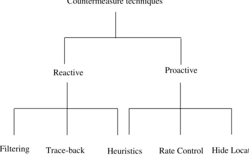
Figure 3.1 shows countermeasure techniques against the DoS problem. Countermeasure techniques are classified into reactive and proactive categories.
Countermeasure techniques
Reactive Proactive
Filtering Trace-back Heuristics Rate Control Hide Location
Figure 3.1: Countermeasure techniques against DoS attacks.
Reactive Techniques They monitor traffic at a target location, waiting for an attack to occur. After the attack is identified, typically via analysis of traffic patterns and packet headers, the countermeasure techniques are established (filtering techniques or source trace back techniques).
• Filtering techniques: in some cases the malicious packet flows can be identified on clearly-defined metrics, e.g., obviously wrong source address or other obvious errors in packet header. Such packet flows can be filtered at routers using some of the following techniques: – Ingress filtering [36] : routers check a packet for its source IP address, and block packets that come from an address beyond the routers’ possible ingress address range. This requires a router to accumulate sufficient knowledge to distinguish between le-gitimate and illele-gitimate addresses, thus it is most feasible in customer networks or at the border of Internet Service Providers (ISP) where address ownership is relatively unambiguous.
– Distributed Packet Filtering (DPF) [70] : it explores the power-law of Internet topol-ogy in source address validation. It can be distributed at core routers to proactively stop packet flows with obviously wrong source addresses, and meanwhile to reactively trace back the attacking sources. Empirical experiments show that DPF can efficiently iden-tify spoofed address outside the autonomous system (AS) where the attackers reside. – Source Address Validity Enforcement (SAVE) [57] : in SAVE, symmetry between
destination forwarding and source validation is explored to realize a protocol similar to Internet routing, but along the reverse direction for maintaining an incoming tree of authenticated sources. The protocol enables SAVE routers to filter malicious packet flows.
1. Since filtering is rendered per-flow, routers must possess sufficient power to process a large number of flows simultaneously.
2. The scalability concern in Internet core routers which could already be heavily loaded due to empirical experience obtained from per-flow based Internet.
3. The accuracy with which legitimate traffic can be distinguished from the DoS traffic. 4. The methods that filter traffic by known patterns or statistical anomalies in traffic
pat-terns can be defeated by changing the attack pattern and masking the anomalies that are sought by the filter.
• Source Traceback [77, 79] : typically, traceback methods include packet-based marking, link testing, and verifying logging. Packet-based marking is normally comprised of two complementary components: a marking procedure executed by routers in the network and a path reconstruction procedure implemented by the victim. The routers augment IP packets with address marks en-route, then the victims can use information embedded in the IP pack-ets to trace the attack back to the actual source. Instead of packet marking, an alternative method is to generate traceback information using separate IP control information such as link testing messages and verifiable logging messages.
However, the source trace-back defense techniques have some problems:
1. The trace-back mechanisms incur overhead in the form of control message processing, storage, and communication.
2. It is not quick and suffers a long delay to protect victim. 3. It does not address the DDoS problem.
4. Often the source of the attack is not real culprit but simply a node that has been re-motely subverted by a cracker (zombie machine). The attacker can just start using another compromised node.
Passive Techniques These techniques do not require detection mechanisms. They prevent tar-gets from DoS problem either by considering some controls in the network or transport layers (e.g., rate control techniques) or by using the interface layer (e.g., hide location techniques).
• Rate Control Techniques [41, 99] : in many cases, there is no clear boundary between DoS attack and insufficient service availability. Countermeasures based on rate control seek to enforce fairness in bandwidth allocation, thus minimize the damage caused by DoS attacks. In fact the idea of doing rate control is to identify the per-packet processing cost for different types of packets, and limited the flow rates such that the end server does not go into overload situation. Different rate limiting policies could be applied to different classes of traffic based on the resources they consume. Figure 3.2 shows rate control techniques from high level view.
However, the main problem of this approach is that its effectiveness is reduced when the number of attacking flows is large. Also if an attacker attacks with different types of packets, it cannot tolerate many attacks very well.
+ - From server Outgoing to server Traffic class 2 Packet in W1 W2 Rate controlled Rate controlled Window controlled Classify Traffic class 1 Traffic class 3 W3 Classify
Figure 3.2: Rate control mechanism from high level view [41].
• Location-Hiding Techniques : location-hiding is an important component of a complete solution to DoS attacks. It gives application sites the capability to hide their locations and thereby preventing DoS attacks, which depend on the knowledge of their locations.
Overlay networks have been proposed as a means for location hiding. An overlay network is used to mediate all communications among application sites. As long as the mediation can be enforced, the overlay network is the only public interface for reaching an application site, and the application site cannot be directly attacked.
Many location-hiding mechanisms use overlay networks. As shown in [54, 84, 85, 97] it is feasible to hide an application’s IP address using an overlay network, thereby enforcing overlay network mediation. Secure Overlay Services (SoS) [54] is an architecture that uses the overlay network for hiding locations. SoS uses filters combined by secret servlets to enforce all application access being mediates through the SoS network. In the SoS archi-tecture, access requests will be authenticated by SOAP nodes and then routed via the Chord overlay network [86] to one of the beacon nodes and then to one of the servlets, which then forwards the requests to the target site which is protected via filters. Figure 3.3 shows the SoS architecture. However, the SOS architecture only simplifies the filtering roles around the target and reduces filtering processing time. Tolerating a large scale DoS attacks (e.g., DDoS) still is a challenge in the SOS architecture.
• Heuristic Techniques : there are some heuristics and creative approaches in both reactive and proactive areas against DoS attacks. Here we mention some of these approaches in brief.
– Replicated Servers : one approach to mitigate DoS attacks against information carri-ers is to massively replicate the content being secured around entire network. To pre-vent access to the replicated information, an attacker must attack all replication points throughout the entire network- a task that is considerably more difficult than attacking a small number of, often co-located, servers. However, there are several reasons why replication is not always an ideal solution. For instance, if the information requires frequent updates, then it is hard to ensure large-scale coherency. Another concern is
Source Point SOAP SOAP Beaco Beaco Beacon Secret S l Secret S l Secret Servlet Target Overlay nodes
Figure 3.3: SoS architecture [54].
the security of the information. Also in applications such as power grid applications this approach is not suitable due to frequent changes in control operations.
– AID Architecture [20] : Chen and Chow describe global anti-DoS services, called AID, which ensures a registered client network the accessibility to any registered server as long as the client does not participate in the attack. The AID service is implemented as a distributed system consisting of a geographically dispersed AID sta-tion, for service registration and anti-DoS operations. When a server is under attack, it will signal its AID station, which propagates the information via the system to the other AID stations. Each AID station enforces all clients’ traffic for the server into the IPsec tunnels.
In summary, each DoS countermeasure has its strengths and weaknesses. It is clear that none of the countermeasures will be the ”silver bullet” that can stop DoS attacks immediately and efficiently. One solution can be combining the strengths of all effective solutions and let them compensate each other’s weaknesses. Of course, this requires a general model to illustrate the shared features of all countermeasures.
3.2.2.2 The OPL Architecture and Operation Description
The OPL is a proactive approach to prevent DoS attacks. The goal of the OPL architecture is to make an intermediate interface by overlay nodes to hide the location of application sites during DoS attacks. OPL allows communication only among confirmed sites. It means that application sites have given each other a prior permission. Typically, this requires that any packet must be authenticated through the OPL architecture before the packet is allowed to be forwarded to the destination.
OPL is an overlay network, composed of nodes that communicate with one another atop the underlying network substrate. In overlay networks, nodes will perform routing functionality to deliver packets from one node in the overlay to another node of the overlay by a defined protocol. The set of overlay nodes of the OPL architecture is known to the public and also to the attackers.


![Figure 3.2: Rate control mechanism from high level view [41].](https://thumb-eu.123doks.com/thumbv2/123dok_br/15453337.1028225/31.892.183.706.132.377/figure-rate-control-mechanism-high-level-view.webp)