Jo˜
ao Ricardo Barros Sousa
Licenciado em Ciˆencias da Engenharia Electrot´ecnica e de
Computadores
Coordinated MultiPoint transmission in
LTE-Advanced femtocell networks
Disserta¸c˜ao para obten¸c˜ao do Grau de Mestre em Engenharia
Electrot´ecnica e de Computadores
Orientador : Lu´ıs Bernardo, Professor Auxiliar com Agrega¸c˜ao, FCT-UNL
Co-orientador : Rui Dinis, Professor Associado com Agrega¸c˜ao, FCT-UNL
J´uri:
Presidente: Prof. Paulo Miguel de Ara´ujo Borges Montezuma de Carvalho Arguente: Prof. Nuno Manuel Branco Souto
Vogais: Prof. Lu´ıs Filipe Louren¸co Bernardo
i
Cooperative MultiPoint transmission in LTE-Advanced femtocell networks
Copyright ➞ Jo˜ao Ricardo Barros Sousa, Faculdade de Ciˆencias e Tecnologia, Universi-dade Nova de Lisboa
Agradecimentos
Em primeiro lugar, gostaria de agradecer ao meu Pai e `a minha M˜ae por todo o apoio, paciˆencia que demonstraram ao longo de todo o meu curso. Um grande Obrigado por terem estado sempre ao meu lado nas boas e m´as alturas e por terem depositado sempre uma grande confian¸ca em mim e me terem dado for¸ca e incentivo. Queria tamb´em agrade-cer aos meus irm˜aos a companhia e o apoio ao longo destes anos.
Quero agradecer tamb´em ao meu orientador, o Professor Luis Bernardo. Um agradec-imento por toda a disponibilidade e pela paciˆencia demonstrada em todas as reuni˜oes. Agrade¸co por todas as extensas revis˜oes textuais e por toda a documenta¸c˜ao disponi-bilizada, sem a qual n˜ao seria poss´ıvel elaborar este trabalho. Ao meu co-orientador, Professor Rui Dinis queria agradecer a disponibilidade e a ajuda na compreens˜ao do mod-elo apresentado.
Um agradecimento a todos os amigos que me acompanharam nesta jornada univer-sit´aria. Desde o in´ıcio ao fim do curso foram muitos os momentos partilhados. Sem d´uvida que a companhia, o apoio e entreajuda foram cruciais nesta etapa da minha vida. De todos eles gostaria de deixar um agradecimento especial ao pessoal da FCT de Set´ubal por todos os momentos nas viagens entre o Monte da Caparica e a nossa cidade.
Um grande Obrigado `a ”malta” de Set´ubal, por terem estado presentes antes, durante e depois do meu curso e me manterem sempre de cabe¸ca erguida. Um agradecimento pela companhia em todas as aventuras e pela amizade forte que desejo que perdure para a vida.
iv
Resumo
As redes m´oveis est˜ao a deparar-se com um aumento do n´umero de dispositivos, do tr´afego de dados m´oveis e da densidade de utilizadores, especialmente em ´areas urbanas. A densifica¸c˜ao espacial que envolve a densa instala¸c˜ao de pequenos n´os e os esquemas de coordena¸c˜ao multiponto que envolvem a coopera¸c˜ao entre recetores, s˜ao vistos como solu¸c˜oes para lidar com este problema em redes Long Term Evolution e 5th Generation densas.
Tanto os esquemas de diversidade temporal no uplink, comoHybrid-Automatic Repeat-reQuest, podem ser usados para resolver colis˜oes e altos niveis de interferˆencia, que re-sultam em taxas de erro elevadas, especialmente nos utilizadores que se encontram no limite da c´elula. Em redes densas, estes esquemas podem ser combinados com esquemas de rece¸c˜ao multipacote para aumentar o d´ebito da rede. No entanto, estes esquemas n˜ao permitem maximizar o d´ebito, pois s˜ao necess´arios slots extra para resolver as colis˜oes. Esquemas de coordena¸c˜ao multiponto foram propostos para redes Long Term Evolution-Advanced, para melhorar a sua capacidade. Nesta disserta¸c˜ao, ´e proposto um esquema de coordena¸c˜ao multiponto onde os pacotes do transmissor s˜ao recebidos simultaneamente em diferentes recetores. Estes est˜ao ligados atrav´es de liga¸c˜oes de alta velocidade a uma unidade de processamento, que ´e respons´avel pela rece¸c˜ao da mensagem utilizando as m´ultiplas c´opias recebidas. Em redes densas, esta¸c˜oes base de baixa potˆencia, como as femtoc´elulas, podem ser usadas para fornecer a diversidade espacial necess´aria para imple-mentar um esquema coordena¸c˜ao multiponto nouplink. De forma a receber a transmiss˜ao de m´ultiplos utilizadores, um esquema de transmiss˜ao h´ıbrido ´e proposto, onde o esquema de diversidade espacial ´e combinado com rece¸c˜ao multipacote e diversidade de potˆencia.
O desempenho do esquema proposto ´e avaliado para um recetor Iterative Block
vi
cision Feedback Equalization. Os resultados mostram que a inclus˜ao de mais um recetor num esquema de diversidade temporal e de potˆencia, permite a rece¸c˜ao da transmiss˜ao de mais utilizadores com uma potˆencia de transmiss˜ao menor. A capacidade da rede tamb´em ´e melhorada, verificando-se o aumento no n´umero de pacotes recebidos por slot de tempo. Palavras Chave: 5G, Cooperative MultiPoint, Multi Packet Reception, Redes
Abstract
Cellular networks are facing a rise in the number of mobile devices, in the mobile data traffic and an increase in the user density, specially in urban areas. Spatial densification, which involves the dense deployment of small nodes (e.g. femtocells), and Coordinated Multi Point schemes, which involve the coordination between receivers, are seen as a solu-tion to cope with this problem in dense Long Term Evolusolu-tion and future 5th Generasolu-tion networks.
Uplink time diversity schemes, such as Hybrid-Automatic Repeat-reQuest, can be used to deal with the collisions and high interference levels which result in high Packet Error Rates, especially for cell edge users. In dense networks, these schemes can be combined with Multiple Packet Reception to increase the throughput of the network. However, they are far from providing the optimal throughput, since extra time slots are needed to solve collisions. Coordinated Multi Point (CoMP) uplink schemes were proposed to be implemented in Long Term Evolution-Advanced networks to enhance their capacity. In this dissertation a CoMP scheme is proposed where the transmitter’s packets are received simultaneously at different Evolved Node Bs (eNodeB). The receivers are connected to a processing unit via a high speed link, which processes the signals with the multiple copies of the messages received. In dense networks, low power base stations such as femtocells may be deployed to provide the spatial diversity needed to implement a CoMP uplink scheme. In order to receive the transmission of multiple users, a hybrid transmission scheme is proposed where the spatial diversity scheme is combined with Multiple Packet Reception and a power diversity scheme.
The proposed scheme’s performance is evaluated for a Iterative Block Decision Feed-back Equalization receiver. Results show that, the inclusion of one more eNodeB in a
viii
power and time diversity reception scheme allows the reception of more users’ transmis-sions with a lower reception power. The network’s capacity is also improved, since more packets are received per timeslot.
Keywords: 5G, Cooperative MultiPoint, Multi Packet Reception,
Acronyms
3G 3rd Generation
3GPP 3rd Generation Partnership Project
4G 4th Generation
5G 5th Generation
ARQ Automatic Repeat-reQuest
BBU BaseBand Unit
BER Bit Error Rate
BS Base Station
CB Coordinated Beamforming
CC Code Combining
CDMA Code Division Multiple Access
CoMP Coordinated Multi Point
CRE Cell Range Expansion
CS Coordinated Scheduling
CSG Closed Subscriber Group
CSI Channel State Information
C-RAN Cloud-Radio Access Network
x ACRONYMS
DAS Distributed Antenna System
DC Diversity Combining
DFE Decision feedback equalization
DFT Discrete Fourier Transform
DFTS Discrete Fourier Transform Spread
DM-RS Demodulation Reference Signal
DPB Dynamic Point Blanking
DPS Dynamic Point Selection
DSL Digital Subscriber Line
eNB Evolved Node B
EPMC Equal Path MultiChannel
FAP Femtocell Access Point
FD Frequency Domain
FDE Frequency Domain Equalization
FDM Frequency Division Multiplexing
FDMA Frequency Division Multiple Access
FEC Forward Error Correction
FFT Fast Fourier Transform
HII High Interference Indicator
HSDPA High-Speed Downlink Packet Access
HSPA High Speed Packet Access
xi
H-ARQ Hybrid-Automatic Repeat-reQuest
IA Interference Alignment
IB-DFE Iterative Block Decision Feedback Equalization
IC Interference Cancelation
ICI Inter-Carrier Interference
ICIC Inter-Cell Interference Coordination
IFFT Inverse Fast Fourier Transform
IMT-A International Mobile Telecommunications-Advanced
ISI Inter symbol Interference
ITU International Telecommunication Union
JP Joint Processing
JT Joint Transmission
LTE Long Term Evolution
LTE-A Long Term Evolution-Advanced
MAC Medium Access Control
MAI Multi Access Interference
METIS Mobile and Wireless Communications Enablers for the Twenty-Twenty Informa-tion Society
MIMO Multiple Input Multiple Output
MMSE Minimum Mean Square Error
MPD Multi Packet Detection
xii ACRONYMS
MUD Multi User Detection
MU-MIMO Multiple User-Multiple Input Multiple Output
OFDM Orthogonal Frequency-Division Multiplexing
OFDMA Orthogonal Frequency-Division Multiple Access
OI Overload Indicator
PAPR Peak Average Power Ratio
PDSCH Physical Downlink Shared Channel
PER Packet Error Rate
PIC Parallel Interference Cancelation
PSK Phase-Shift Keying
QAM Quadrature Amplitude Modulation
QoS Quality of Service
QPSK Quadrature Phase Shift Keying
RAN Radio Access Network
RNTP Relative Narrowband Transmit Power
RRH Remote Radio Heads
SC Single Carrier
SC-FDE Single-Carrier Frequency Domain Equalization
SIC Successive Interference Cancelation
SINR Signal-to-Interference-plus-Noise Ratio
SU-MIMO Single User-Multiple Input Multiple Output
xiii
TP Transmission Point
TSG-RAN Telecommunication Solutions Group-Radio Access Network
UE User Equipment
UMTS Universal Mobile Telecommunication System
UTRA UMTS Terrestrial Radio Access
UTRAN UMTS Terrestrial Radio Access Network
WCDMA Wide-Band Code-Division Multiple Access
Contents
Agradecimentos iii
Resumo v
Abstract vii
Acronyms ix
1 Introduction 1
1.1 Current Context . . . 1
1.2 Objectives and Contributions . . . 2
1.3 Dissertation Structure . . . 3
2 State of the Art 5 2.1 Long Term Evolution . . . 5
2.1.1 Evolution to LTE Advanced . . . 6
2.2 Multiple Access Schemes . . . 7
2.2.1 Orthogonal Frequency Division Multiplexing . . . 7
2.2.2 Single-Carrier with Frequency Domain Equalization . . . 9
2.3 Wireless Interference Networks . . . 9
2.3.1 Hybrid-ARQ with soft combining . . . 10
2.3.2 Multiple Packet Reception based on Time Diversity . . . 11
2.3.3 Interference Alignment . . . 12
2.3.4 Inter-Cell Interference Coordination in Homogeneous Networks . . . 14
2.4 Coordinated multipoint transmission/reception . . . 16
2.4.1 Downlink COMP Schemes . . . 17
2.4.2 Uplink COMP Schemes . . . 19
2.5 Femtocells and Heterogeneous Networks . . . 20
2.5.1 Femtocell Access Modes . . . 21
2.5.2 Distributed Antenna System . . . 21
2.5.3 Interference Scenarios in Heterogeneous Networks . . . 24
2.5.4 Interference Scenarios in Femtocell Networks . . . 25
xvi CONTENTS
3 IB-DFE receiver model with uplink signal diversity 29
3.1 LTE Femtocell Joint Processing . . . 29
3.1.1 Network Architecture . . . 31
3.1.2 Mobile device association to the eNB . . . 31
3.2 Receiver Structure . . . 32
3.2.1 Linear Receiver Model . . . 33
3.2.2 Iterative Receiver with soft decisions Model - IB-DFE . . . 38
3.3 Uplink signal Diversity . . . 44
3.3.1 Power Diversity on the IB-DFE receiver . . . 45
3.3.2 Spatial Diversity on the IB-DFE receiver . . . 49
3.3.3 IB-DFE receiver performance with spatial diversity . . . 50
4 Interference Model and Hybrid CoMP Scheme 55 4.1 Interference model with incomplete resolution at the receiver . . . 56
4.1.1 Interference model with incomplete channel knowledge . . . 56
4.1.2 Network elements distribution . . . 58
4.1.3 Interference model performance results . . . 59
4.2 Spatial, Time and Power diversity hybrid scheme . . . 63
4.2.1 Hybrid Diversity Scheme implementation . . . 64
5 Conclusions 77 5.1 Final Considerations . . . 77
5.2 Future Work . . . 78
List of Figures
2.1 OFDM sub-carriers, adapted from [TW11]. . . 8
2.2 Two transmitters simultaneously send 1 message to each receiver over 3 channel usages using Blind Interference Alignment . . . 15
2.3 Coordinated Multipoint Reception and Transmission techniques . . . 17
2.4 Femtocell Access Point Connection to the Operators Core Network using a DSL link . . . 22
2.5 C-RAN network Deployment . . . 23
2.6 High Inter-cell Interference caused by the increase in coverage area of the low power cell. Adapted from [DPS13] . . . 25
3.1 Spatial diversity on the uplink . . . 30
3.2 MPD and Hybrid MPD+DC technique usage to improve reception at the eNB . . . 33
3.3 Linear Receiver Block Diagram . . . 35
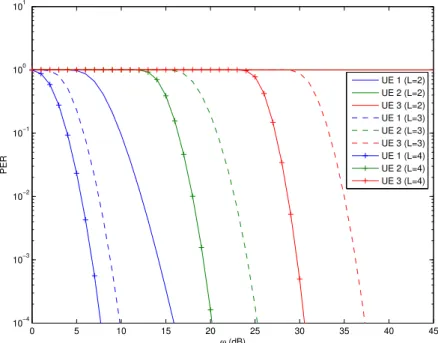
3.4 PER over ω of 3 UEs in 3 different time diversity scenarios . . . 38
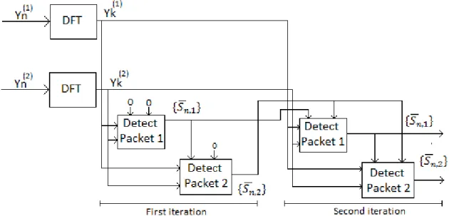
3.5 Detection diagram of two packets . . . 39
3.6 Block Diagram of one iteration of the IB-DFE receiver with soft decisions . 40 3.7 PER over ω for 3 UEs with 3 different number of iterations . . . 43
3.8 Aggregate average throughput for the fourth iteration of the receiver of the transmission of 2 UEs with different power spacing . . . 47
3.9 Aggregate average throughput for the fourth iteration of the receiver of the transmission of multiple UEs with different power spacing . . . 48
3.10 Content received at the eNBs when two UEs have their signal provided with spatial and time diversity . . . 50
3.11 Topology used for the simulation of 2 UE’s uplink transmissions provided with spatial diversity . . . 51
3.12 Average Aggregate Throughputs for the fourth iteration of the receiver, for increasing distances of 2 MTs when using Spatial Diversity . . . 52
3.13 Aggregate average throughput for the fourth iteration of the receiver of the transmission the same transmission provided with time diversity and provided with spatial diversity . . . 53
xviii LIST OF FIGURES
4.1 Average aggregated Throughput in the IB-DFE receiver over UE density of 2 UEs using a complete channel resolution interference model and an incomplete channel resolution approximation. . . 60 4.2 Portion of the network with the UEs available for reception at eNB 1. . . . 61 4.3 PER of UE 5 and 6 for the fourth iteration of the receiver in each different
interference scenario. . . 63 4.4 Flow Chart explaining UE association to one eNB and the power control
scheme. . . 66 4.5 Uplink transmission of two UEs with and without using CoMP . . . 67 4.6 Portion of the network considered in the Hybrid Diversity scheme simulation
with high device density . . . 69 4.7 PER of UEs obtained in both diversity simulated scenarios with high density 71 4.8 Average Aggregate Throughput of both diversity simulated scenarios with
high density . . . 71 4.9 Portion of the network considered in the Hybrid Diversity scheme simulation
with low device density . . . 73 4.10 PER of UEs obtained in both diversity simulated scenarios with low density 75 4.11 Average Aggregate Throughput of both diversity simulated scenarios with
List of Tables
3.1 Specifications for the Linear Receiver performance simulation . . . 37
3.2 Specifications for the Iterative Receiver performance simulation . . . 43
3.3 Specifications for the power diversity simulation . . . 46
3.4 Specifications for the power and time diversity simulation with different number of UEs . . . 48
3.5 Specifications for the spatial diversity simulation with two UEs . . . 51
3.6 Specifications for the time diversity simulation with two UEs . . . 53
4.1 Specifications for the interference model performance simulation. . . 60
4.2 Specifications for the simulations with two different interference conditions. 62 4.3 Specifications for the interference model performance simulation with high device density . . . 70
4.4 Specifications for the interference model performance simulation with low device density. . . 74
Chapter 1
Introduction
1.1
Current Context
Mobile wireless communication has experienced a sharp growth over the past years, mainly due to the breakthrough of affordable mobile devices (e.g. smart phones and tablets). Wireless operators have accepted the challenge of cost-effectively supporting a great increase in the traffic demand. Network densification, which is a combination of spatial densification (e.g. dense deployment of small cells, increase the number of anten-nas per node) and spectral aggregation (i.e. utilizing larger portions of electromagnetic spectrum), is seen as a key mechanism for wireless evolution [BLM+14].
The deployment of additional macro Evolved Node B (eNB)s involves significant costs and elaborate site planning. Heterogeneous networks provide spatial densification and in-volve the deployment of low power nodes inside a macro cell coverage area. The users in the macro cell can also connect to multiple smaller cells (e.g. femtocells), enabling a decrease of the device density per small cell, if an uniform distribution of users among all the eNBs is ensured. These deployments optimize performance in networks where there is unequal user or traffic distribution by improving cell-edge and/or indoor performance [BLM+14]. Femtocell nodes have a low installation cost and are easy to deploy, which
make them attractive solutions to provide spatial densification.
The deployment of low power nodes enables a reduction in the distance between the reception points and the transmitters, leading to an increase in the interfering signal levels, therefore the development of interference mitigation techniques is crucial to improve link
2 CHAPTER 1. INTRODUCTION
efficiency. One of Long Term Evolution (LTE)’s latest releases is known as Long Term Evolution-Advanced (LTE-A) and proposes the use of Coordinated Multi Point (CoMP) reception and transmission techniques. CoMP uplink schemes require coordination be-tween reception points in order to reduce inter cell interference and collisions bebe-tween transmissions. These techniques can be applied in a Distributed Antenna System (DAS) (e.g. Cloud-Radio Access Network (C-RAN)), where multiple reception points are con-nected to the same processing unit via a high performance fiber-based backhaul, in order to reduce the interfering User Equipment (UE)’s effects. They are also envisioned as part of the technologies that will be applied in the future 5th Generation (5G) cellular networks [ABC+14].
1.2
Objectives and Contributions
This dissertation explores the capacity enhancements with spatial densification in high density heterogeneous networks. In these networks, multiple reception points (e.g. femtocells) with small distances between them are available to receive the device’s trans-mission, to balance the network’s load and to provide joint reception. CoMP is employed to reduce the interference and optimize the performance of the receivers. A Single-Carrier Frequency Domain Equalization (SC-FDE) scheme is used by the mobile devices in the uplink transmission, to assure resistance to frequency selective fading and a lower Peak Average Power Ratio (PAPR), compared to Orthogonal Frequency-Division Multiplex-ing (OFDM). Furthermore, the receiver considered is an Iterative Block Decision Feed-back Equalization (IB-DFE) receiver that can employ Multiple Packet Reception (MPR) and Diversity Combining (DC) techniques to improve reception.
im-1.3. DISSERTATION STRUCTURE 3
provements that they can bring to the reception scheme. A hybrid reception scheme that combines these diversity techniques, allowing the increase of the number of users handled per receiver, is also proposed, simulated and compared with the time and power diversity uplink scheme.
1.3
Dissertation Structure
Chapter 2
State of the Art
2.1
Long Term Evolution
Nowadays, due to the technological evolution of mobile networks and devices, the world is facing a rise in the amount of users and a diversification of the services provided by mobile devices. For this reason, in order to assure the satisfaction of the user, there was the necessity to provide higher peak and sustained throughputs, larger user capacity and greater spectral efficiency in mobile networks. Universal Mobile Telecommunication Sys-tem (UMTS) LTE, also known as the 4th Generation (4G) of mobile telecommunications technology, is the wireless broadband technology created by the 3rd Generation Partner-ship Project (3GPP) destined to cope with this demand and one of its main challenges is to provide support to the internet based services on mobile devices.
The evolution from 3rd Generation (3G) networks to 4G, started with the first release of Wide-Band Code-Division Multiple Access (WCDMA) Radio Access, entitled release 99, which included circuit switched voice and video services, and circuit and packet switched data services. High-Speed Downlink Packet Access (HSDPA) was introduced in release 5 and High-Speed Uplink Packet Access (HSUPA) in release 6 (these two features are often referred together as High Speed Packet Access (HSPA) [DPS13]). These protocols increased the network’s peak data rates, capacity and reduced the latency leading to a mobile system that surpassed the definition of 3G mobile networks. 3GPP defined the specifications for UMTS LTE called UMTS Terrestrial Radio Access (UTRA) and UMTS Terrestrial Radio Access Network (UTRAN) in Release 8 [LKL+12]. With a 20 MHz
6 CHAPTER 2. STATE OF THE ART
bandwidth it enabled peak data rates that exceeded 300 Mb/s on the downlink and 75 Mb/s on the uplink. It was one of the first releases to be commercialized and it is mainly deployed in a macro/micro cell layout and uses OFDM as the downlink multiple access scheme and Discrete Fourier Transform Spread (DFTS)-OFDM, also known as SC-FDE, as the uplink multiple access scheme [PFD11]. LTE Release 9 includes features that pro-vide minor enhancements to the previous release such as dual layer beam forming and time-difference-of-arrival-based location techniques [GRM+10].
2.1.1 Evolution to LTE Advanced
LTE-A, also known as 3GPP Release 10, is not a new radio access scheme but repre-sents a significant improvement of LTE Release 8, providing a better user experience. It was designed to meet the International Mobile Telecommunications-Advanced (IMT-A) requirements defined by the International Telecommunication Union (ITU) [PFD11] and uses a variety of techniques such as: carrier aggregation, downlink and uplink spatial multiplexing and CoMP transmission and reception. It is also designed to support its im-plementation in heterogeneous networks, where low-power nodes are introduced in a macro cell network. These nodes lead to enhancements in the network coverage area and capacity [GRM+10]. Carrier aggregation allows achieving wider bandwidths, up to a maximum of
100 MHz [GRM+10]. This technique consists in the usage of multiple frequency blocks
known as Component Carriers, which do not need to be contiguous, for the transmission [PFD11]. Carrier aggregation can also be useful to heterogeneous network deployments because different component carriers can be joined together. The peak data rate to be achieved in Release 10 is 1 Gb/s in the downlink and 500 Mb/s in the uplink [GRM+10]. This can be attained by increasing the number of Component Carriers and the number of antennas used by the transmitter and receiver.
2.2. MULTIPLE ACCESS SCHEMES 7
to cooperate in the transmission or reception, leading to the mitigation of interference in dense networks and to the rise in the data rate of a cell edge user.
LTE-A is a step towards the transition from the 4G to the 5G wireless system. 5G net-works will respond to the expected traffic volume explosion and to the new requirements through a combination of evolved existing technologies and new radio concepts [OBB+14]. Extreme network densification and offloading are seen as key technologies to improve spec-tral efficiency (i.e. more active nodes per unit area) and to achieve the higher data rates required to support the traffic increase [ABC+14]. In this dissertation, the benefits that
come from network densification are analysed.
2.2
Multiple Access Schemes
In a cellular network, it is hard to provide coordination amongst users, so there is the necessity to design schemes that enable multiple users to simultaneously use the transmis-sion resource in the most efficient way. The following subsections present the OFDM and SC-FDE schemes.
2.2.1 Orthogonal Frequency Division Multiplexing
OFDM is a method of digital modulation based on Frequency Division Multiplex-ing (FDM) and has been adopted as the standard multiple access scheme in LTE and LTE-A. FDM uses band pass filters on the receiver to allow channel sharing over the same bandwidth, with each user transmitting on a sub-band. Adjacent frequency bands are used for transmission, therefore a guard band must be added between multiple channels to allow the receiver to filter successfully the desired signal.
8 CHAPTER 2. STATE OF THE ART
block) is also inserted at the beginning of each block. These symbols are discarded at the receiver and their purpose is to increase the reliability by preventing the contamina-tion of a block with Inter symbol Interference (ISI) from the previous block and to make the received block appear to be periodic [FABSE02], allowing an efficient Fast Fourier Transform (FFT) operation.
Figure 2.1: OFDM sub-carriers, adapted from [TW11].
This scheme is a Multi-Carrier transmission scheme so the Inverse Fast Fourier Trans-form (IFFT) is applied to blocks ofM data symbols at the transmitter to generate a large number of narrowband sub-carriers that carry different data streams and are transmitted concurrently. Each sub carrier is modulated with a conventional modulation scheme such as Quadrature Amplitude Modulation (QAM) or Phase-Shift Keying (PSK) at a lower data rate than the original data stream, because the data can be spread by multiple car-riers. This is an advantage because degradations of the channel are easier to cope at sub carrier level [TW11]. In addition, the use of narrowband sub carriers leads to channels roughly constant over each given sub band, which make equalization simpler at the re-ceiver [BRdTF+08].
2.3. WIRELESS INTERFERENCE NETWORKS 9
2.2.2 Single-Carrier with Frequency Domain Equalization
A Single Carrier (SC) system consists in the transmission of a single modulated carrier at a high symbol rate. Equalization is known as the compensation of the linear distortion caused by channel frequency selectivity [BDFT10]. Frequency Domain Equalization (FDE) is more efficient than time domain equalization because operations are carried out in blocks of data at a time [FABSE02]. Frequency domain non-linear equalization consists in using an adaptive equalizer at the receiver to remove ISI, which is one or more linear filters, followed by a cancelling of the remaining interference by using previous detected data [BDFT10]. Decision feedback equalization (DFE) is a non-linear equalization technique that can be used to cancel this interference. In DFE equalizers, symbol-by-symbol de-cisions are made and the feedback of previous detected symbols is used to remove their interference effect.
OFDM is not the most recommended modulation scheme for the uplink transmission due to the high envelope fluctuations of the waveform [GDBO12] that results of the trans-mission of data over parallel sub carriers, which can constructively add in phase. This leads to a signal with high PAPR requiring highly linear power amplifiers to avoid inter-modulation distortion. High PAPR is critical in the uplink due to power constraints in the UE [BRdTF+08].
SC modulation methods combined with FDE deliver a performance similar to OFDM, guaranteeing immunity to the time-distortion effects introduced by frequency selective fad-ing, with the same overall complexity [FABSE02]. Furthermore the PAPR of the trans-mitted signal is smaller, since only a single carrier is being used. This enables the use of a cheaper power amplifier than a comparable OFDM system, which is one of the more costly components in a consumer broadband wireless transceiver [FABSE02].
2.3
Wireless Interference Networks
10 CHAPTER 2. STATE OF THE ART
networks.
In interference networks there are two different approaches to handle interfering ter-minals based on the interference power: if it is weak it should be ignored and treated as noise, as if the interfering terminal is not present in the network; if it is considered to be strong, it should be avoided or cancelled using multiplexing schemes or appropriate pre coding.
These networks deal with the possibility that packets can arrive incorrect or flawed to the receiver due to poor transmission conditions, which can result of high interference level, high noise level or packet collisions. Various techniques that were designed to pro-vide reliability to data transmission over these networks are described in the following subsections.
2.3.1 Hybrid-ARQ with soft combining
The Automatic Repeat-reQuest (ARQ) protocol is used to provide reliability in a data transfer. Basically, once an error is detected in a packet at the receiver, it is discarded and a retransmission is requested to the transmitter. In 1960 a protocol was designed by Wozencraft and Horstein, in which both error correction and error control were provided, known as type-I Hybrid-Automatic Repeat-reQuest (H-ARQ) [CHIW98]. It provided a significant improve in the reliability and throughput provided by pure ARQ protocols, since H-ARQ used the Forward Error Correction (FEC) technique to handle the most common errors, therefore leading to a reduction in the number of retransmissions re-quested to the transmitter [CHIW98]. However this protocol can be inefficient in good transmission conditions, since the extra parity bits that provide FEC are only increasing the message length and will be wasted, because a strong signal allows the reception of error free messages.
2.3. WIRELESS INTERFERENCE NETWORKS 11
Nowadays these packet combining schemes can be arranged into two categories: Code Combining (CC) and DC schemes. Type II H-ARQ is considered an early version of a code combining scheme. In CC schemes multiple copies of the same packet are concatenated to form noise corrupted codewords with increasingly longer codewords and lower rate codes [CHIW98]. In DC schemes, the individual symbols from identical copies of a packet are combined to create a single packet with more reliable symbols. The DC schemes, such as Sindu’s work [CHIW98], usually have a worse performance than CC schemes, however are simpler to implement [GDBO12].
2.3.2 Multiple Packet Reception based on Time Diversity
In networks where multiple users try to access the channel simultaneously, there will be collisions and it is the objective of Medium Access Control (MAC) protocols to avoid them by trying to schedule the multiple transmissions in the most efficient way. H-ARQ techniques are not the best option when multiple users are trying to access the channel because when there is a collision, a user is required to transmit in the next time slot with a given probability [GDBO12]. This does not allow achieving the optimal system throughput, because in a collision between two packets, at least two more time slots will be required, to assure the reception. Furthermore with the usage of this retransmission technique, the flawed packets were still being discarded if the errors were not corrected and no information was exploited from them.
MPR techniques use the resulting signal from a collision between multiple terminals to separate the packets involved [GPB+11]. Time diversity MPR is an approach where the terminals involved in a collision, temporally retransmit the packets under different transmission conditions (e.g. uncorrelated channels, different packet phase rotation, cyclic shifts or frequency-domain scrambling), so the base station can separate successfully all the packets involved in a collision.
Multiple Packet Reception Techniques
12 CHAPTER 2. STATE OF THE ART
suitable to implement at the eNBs and apply to uplink transmissions [ZANM13]. There are two subdivisions of suboptimal MPR techniques: linear and non-linear.
Linear MPR involves the application of a linear transformation to the soft outputs of the conventional detector to produce a new set of decision variables, decoupling Multi Access Interference (MAI) [LSW12]. The most well-known linear MPR techniques are the decorrelated detectors and the Minimum Mean Square Error (MMSE) detector.
Non-linear MPR can be defined as the reduction of interference at the receiver with the aid of channel estimations provided to the receiver [LSW12]. MultiStage Interference Cancellation is a category of non-linear MPR, where interference cancellation can be carried successively (Successive Interference Cancelation (SIC)) or in parallel (Parallel Interference Cancelation (PIC)). On one hand SIC resolves collisions (i.e. simultaneous arrival of two or more packets to the receiver) by detecting one user per iteration [LSW12]. Considering the collision between the transmissions of two users, the receiver can decode the strongest signal, subtracting it from the combined signal, afterwards the weaker signal can be extracted from the residue. When there is the collision between the transmission of multiple users, firstly the user that delivered the strongest signal is detected and subtracted from the combined signal, afterwards the second strongest and so on [SSCN10], depending on the number of iterations. On the other hand, PIC simultaneously removes from each user the interference produced by the remaining, so it has a higher complexity but a lower latency than SIC [ZANM13]. There is also the Multi User Detection (MUD) technique, that consists in the identification of the signature of each user (e.g. user spreading code used in Code Division Multiple Access (CDMA) transmission) to detect the most probable signal transmitted by a user [ZANM13].
2.3.3 Interference Alignment
2.3. WIRELESS INTERFERENCE NETWORKS 13
Division Multiple Access (FDMA), where users transmit at the same time but have their data transmission allocated to different frequency bands.
However multiplexing methods are far from optimal when channel capacity is taken into account [Jaf], since the transmission resource is being cut into multiple smaller pieces. Depending on the amount of users, this leads to the reduction of the data transmission rate of each individual user. The ideal situation would be to have multiple users transmit-ting simultaneously over the same time and frequency, but this leads to the interference of undesired signals with the transmission of a user.
Interference Alignment (IA) is a pre coding technique that attempts to align multiple interfering signals in space, time or frequency, turning them apparently into one interfer-ing signal not aligned with the intended signals received [Jaf]. Theoretically it allows each transmitter-receiver pair to access half of the spectrum as if there was no interference, since interference can be subtracted. IA is feasible if there is an intelligent design of the signals. It can be done in two ways: by manipulating the transmission channel (using Blind Interference Alignment) or by manipulating the signal input [Jaf].
Although IA can be achieved, shaping the information signal is not a practical ap-plication, since it requires that transmitters have full channel knowledge, which is rarely available on wireless networks [Jaf]. If the transmitter has the knowledge of the coefficients that model the channel to the undesired receivers, it just has to invert these coefficients and multiply the signal by them. In this way when all the interfering messages cross the channels they all appear aligned into the same subspace at the receiver and can be treated as a single variable [Jaf].
Blind Interference Alignment
14 CHAPTER 2. STATE OF THE ART
improvement to the network capacity [Jaf]. The change in the channel coefficients can be obtained by changing the transmission frequency for a frequency selective fading receiver, by transmitting in a different time slot for a time selective fading receiver or by changing the antenna that receives the transmission at the receiver if it has multiple antennas. Channel shaping allows each receiver to receive the data transmission mixed with the interference. Since, the interfering signal channel may remain constant over simultaneous transmissions, it can be subtracted from the desired signal at the receiver. In a network with M data transmitters and N data receivers a maximum of M ∗N symbols over
M +N−1 channel usages can be send with Blind IA usage [Jaf].
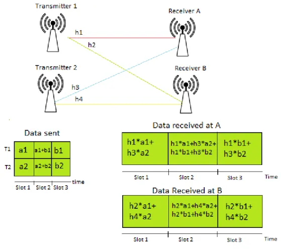
Figure 2.2 depicts a transmission where two transmitters want to send one symbol to each receiver: transmitter 1 wants to senda1 to receiver A andb1 to receiver B, transmitter 2 wants to senda2 to A andb2 to B. It can be observed that with Blind IA it is possible to transmit four symbols over 3 channel usages. If the transmission received in the third slot is subtracted to the data received by A in the second slot, the result are two transmissions free of interference (transmission on slot 1 and transmission on slot 2).
2.3.4 Inter-Cell Interference Coordination in Homogeneous Networks
Interference between cells, also known as Inter-cell Interference, is caused by full fre-quency reuse in 3G and 4G networks, where no frefre-quency partitioning happens between eNBs of the same network [PNS10], so every base station uses full bandwidth for trans-mission. This leads to performance degradations due to interference, especially at the cell edge where downlink signals from different adjacent transmission cells are received with similar power and uplink signals are transmitted with higher power since they experience high path losses.
2.3. WIRELESS INTERFERENCE NETWORKS 15
Figure 2.2: Two transmitters simultaneously send 1 message to each receiver over 3 channel usages using Blind Interference Alignment
[PNS10], however the reaction to them was not specified. So it is up to the eNB manufac-turer or network manager to define the response to incoming ICIC related messages.
16 CHAPTER 2. STATE OF THE ART
The neighbouring cell that receives this message should change its scheduling to improve the interference situation for the eNB issuing the OI [DPS13].
The Relative Narrowband Transmit Power (RNTP) message is used to avoid down-link interference. It contains 1 bit per downdown-link physical resource block, which is set to indicate if the transmission power of the eNB in that specific resource block is going to be greater than a certain threshold [PNS10]. It is a proactive tool since it allows neighbouring cells to use this information to schedule their users’ transmissions before the interference happens.
2.4
Coordinated multipoint transmission/reception
Although there were improvements in the peak data rate and network capacity in LTE networks with the upgrade of downlink and uplink techniques such as Single User-Multiple Input User-Multiple Output (SU-MIMO) and User-Multiple User-User-Multiple Input User-Multiple Output (MU-MIMO), there was still room for improvement with appropriate coordination between points. A point is defined as a set of geographically collocated transmit antennas [LKL+12]. CoMP techniques can be defined as the cooperation between multiple points
in order to allow the enhancement of data transmission or reception in cellular networks. They are based on the principle of spatial reuse, where the same time-frequency resource is used for communication at different locations [DPS13]. CoMP was adopted as a key to improve the cell edge user data rate and the spectral efficiency in LTE-A networks at the Telecommunication Solutions Group-Radio Access Network (TSG-RAN) Work Group 1 (WG1) meeting in the 3GPP [SKM+10], allowing higher throughputs. These techniques try to constructively exploit or avoid Inter-Cell interference through coherent base station cooperation [IDM+11]. A study conducted by the 3GPP showed that CoMP can provide
not only a higher cell edge user throughput but also an increase in the average system throughput [SKM+10].
2.4. COORDINATED MULTIPOINT TRANSMISSION/RECEPTION 17
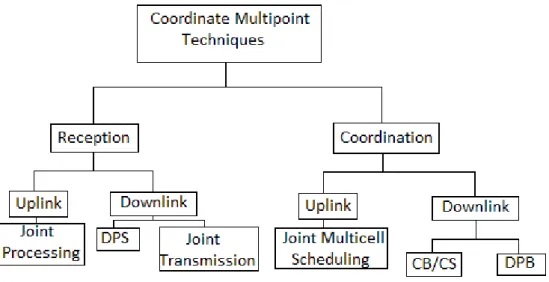
Figure 2.3: Coordinated Multipoint Reception and Transmission techniques
2.4.1 Downlink COMP Schemes
LTE Downlink CoMP schemes can be divided in two different approaches: multi-point coordination, where only one specific multi-point does the transmission but scheduling and link adaptation is done in a cooperative way between transmission points; and multi-point transmission, where the transmission to a single terminal is done simultaneously or dynamically by different transmission points.
Downlink Multipoint Coordination
There were two distinct multipoint coordination schemes presented by 3GPP: Coordinated Beamforming (CB)/Coordinated Scheduling (CS) and Dynamic Point Blanking (DPB). CB is a multipoint coordination scheme where the user beam forming decisions are made in a coordinated manner between the different transmitters. Beam forming weights are generated in a cooperative way for each terminal, by coordinating the pre coder so that the interference to other terminals is reduced [SKM+10] and the power gain in the direction
of the receiver is maximized [DPS13], consequently increasing the Signal-to-Interference-plus-Noise Ratio (SINR) of cell edge users.
18 CHAPTER 2. STATE OF THE ART
in distributed networks or by the exchange of scheduling information and ICIC messages between transmitters; this information is used to decide which Transmission Point (TP) should transmit in each slot and to which terminal, in order to prevent the interference experienced by the terminals. The data for the transmission is only available at one base station, called serving cell and the coordination is considered to be semi-static, meaning that it requires previous planning [SKM+10].
LTE-A CoMP admits a more dynamic variation of coordinated scheduling known as DPB. Basically it consists in blanking relevant time/frequency resources in interfering ad-jacent transmission points on a subframe basis. In order to do that, the network needs to be able to predict dynamically not only the impact on the expected channel quality from neighbouring TPs, but also the improvement of the channel quality if the interfering TPs were not transmitting [DPS13]. This can be done using Channel State Information (CSI) Reports, which reflect different hypotheses regarding the interference of the adjacent TPs.
Downlink Multipoint Transmission
The downlink multipoint transmission schemes can be divided into: Dynamic Point Selection (DPS), where the transmission point can be changed dynamically, and Joint Transmission (JT), where concurrent transmissions are done by multiple points.
The DPS technique only allows the transmission from one point at a single time, how-ever this point can be changed dynamically and this means it can be changed on a sub frame basis. The terminal does not need to be aware of the change in transmission point since it will only see a different Physical Downlink Shared Channel (PDSCH) transmission [DPS13], containing a different Demodulation Reference Signal (DM-RS). The terminal should also provide CSI reports to the different TPs to assist the network in the dynamic selection of the optimal one.
2.4. COORDINATED MULTIPOINT TRANSMISSION/RECEPTION 19
correlation [DPS13] and can improve coherently or non-coherently the transmitted signal. Coherent JT exploits the relations in phase and amplitude of downlink signals from dif-ferent TPs to form precoders that increase the signal quality and throughput, similarly to the coordinated beam forming technique but with the antennas corresponding to different TPs [DPS13]. Non-coherent JT just consists in the delivery of multiple copies of the signal to the receiver by different TPs, representing a power gain in the transmission. Since the extra transmission can produce harmful interference, non-coherent JT is only beneficial in a low load situation where there is no terminal using the extra TP.
2.4.2 Uplink COMP Schemes
Uplink signals can cause interference to nearby receivers which are not the destination of the transmission. Therefore uplink CoMP schemes and better receiver algorithms were designed and standardized, which aim at providing coordination among eNBs of different manufacturers and improving the link quality and cell edge throughput [LKL+12].
The same principles applied in Downlink CoMP schemes can be applied to Uplink CoMP schemes [DPS13]. Therefore, these schemes can be classified as: uplink multipoint coordination schemes, where there is a dynamic coordination of the uplink transmission to reduce interference; and uplink multipoint reception schemes, where the uplink trans-mission is received at multiple points. Uplink CoMP techniques present less impact on the radio interface specifications for LTE-A than downlink schemes [DPS13] since all the uplink scheduling decisions are made by the network and because a terminal does not need to know where its transmission was received, as long as it receives the corresponding feedback.
Joint multi cell scheduling is a multipoint coordination scheme where the exchange of scheduling and channel information (e.g. SINR) messages between eNBs is required and provided not only to associated terminals but also to neighbouring terminals, in order to allow dynamic link adaptation. This information causes moderate backhaul traffic and requires very low latency [SKM+10], because the channel state indicators lose its purpose if they become outdated.
20 CHAPTER 2. STATE OF THE ART
channels at the transmitters, beam-forming is harder to implement on the uplink [DPS13]. However, diversity can be provided with Joint Processing (JP) also known as Cooperative Multiple Input Multiple Output (MIMO), if there is a low mutual correlation between channels. This multipoint transmission technique involves the coordinate transmission of a single traffic flow over multiple points and the exchange of information between cooper-ating cells, such as the quantized baseband samples of the different receivers, channel state information and resource allocation tables. This causes a high amount of traffic between receivers and increases network complexity, therefore it turns out easier to provide intra-site (i.e. inside the same cell or cluster) JP, since it requires a lower interface throughput and supports a higher latency than intersite JP [IDM+11].
2.5
Femtocells and Heterogeneous Networks
Providing very high system capacity and per-user data rates requires the densification of the network nodes [DPS13], because this leads to the reduction of the distance between the transmitter and the receiver, which diminishes signal fading caused by the path loss attenuation. Low power nodes can coexist in a macro cell network layout forming hetero-geneous networks and are seen as a solution to support the increasing demand for network capacity in areas with high clustering of users and high traffic load. Heterogeneous net-works are characterized by harsh inter cell interference, due to the different power and types of antennas [LKL+12]. However, these networks will be architected to incorporate an increasingly diverse set of frequency bands [BTAS14].
2.5. FEMTOCELLS AND HETEROGENEOUS NETWORKS 21
cost they have [CAG08], since usually these low range cells are bought and installed by the end user.
5G networks require an economically sustainable capacity and performance growth strategy [BTAS14]. Heterogeneous networks are seen as the most promising low-cost ap-proach to meet the industry’s capacity growth needs and deliver an uniform connectivity experience [BTAS14], since small cells can be added to increase capacity in high user demand areas and to provide coverage to zones that the macro cell does not cover.
2.5.1 Femtocell Access Modes
Femtocells work as an indoor access point, known as Femtocell Access Point (FAP) [ZANM13], a data connection to multiple devices. Femtocells can be deployed in: an open access, closed access or hybrid access mode. The first consists in the deployment of these low power nodes inside public buildings, improving the coverage of every user in a certain public area, therefore reducing macro cell load and improving their SINR and consequently the network capacity.
The closed access mode is the installation of low power nodes inside closed private buildings, leading to the increase of indoor voice and data coverage and reduction of non-mobile traffic load in the macro cell. It uses a fixed group of subscriber home users, known as Closed Subscriber Group (CSG) [DPS13]. There is also the hybrid access mode, where a limited amount of the femtocell resources are available to all users, while the rest is dedicated solely to the CSG.
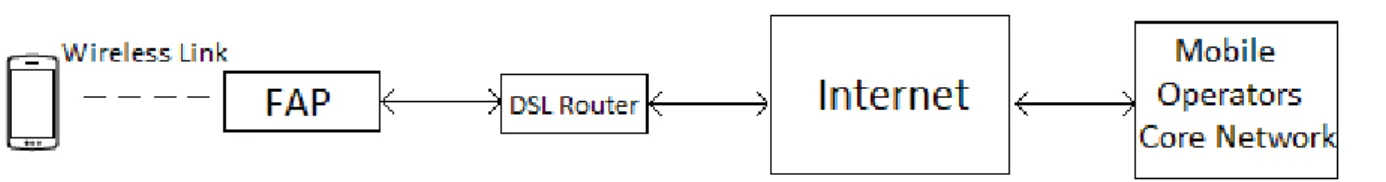
Either way the FAP needs be connected to the core operator network via Digital Subscriber Line (DSL), optical fiber cables or cable broadband connection to deliver its data. The connection scheme is depicted below in figure 2.4.
2.5.2 Distributed Antenna System
22 CHAPTER 2. STATE OF THE ART
Figure 2.4: Femtocell Access Point Connection to the Operators Core Network using a DSL link
scheme can be generalized into the heterogeneous network layout where home base sta-tions are coordinated together with the high power base stasta-tions.
Although the DAS is seen as a good implementation for most heterogeneous networks, some problems can rise in the use of centralized coordination between macro layer networks and femtocell networks. Because of the ad hoc deployment of these low power networks, it becomes hard to provide centralized coordination due to the difficulty in keeping track of neighbouring femtocells [ZANM13].
Cloud-RAN architecture
The Radio Access Network (RAN) of telephone companies consists of base station and base station controllers and provides reliable and available signal coverage over a certain area. Cost savings are only possible if the current RAN architecture is changed, because the biggest capital and operational expenditures of a cell site are the base stations hardware, software and the support of the equipment [HDDM13].
2.5. FEMTOCELLS AND HETEROGENEOUS NETWORKS 23
frequency transposition, power amplification) [LKL+12][HDDM13] in a wide geographical area. The architecture of a C-RAN network is illustrated in figure 2.5.
Figure 2.5: C-RAN network Deployment
The decoupling of the BBU functions from the cell site leads to cheaper cell sites due to the lower energy consumption (C-RAN is also known as Green RAN [HDDM13]) and lower complexity of RRH modules, opening up the possibility for an increase of RRHs de-ployment in areas with high traffic loads, consequently increasing their throughput. This topology allows a BBU to manage several RRHs, leading to unified scheduling of incoming signals and ARQ operations. C-RAN leads to an optimal resource sharing because there is not a fixed dependency between the RRH and the BBU functions, allowing the BBU to allocate dynamically its resource pool according to the network’s needs [HDDM13]. The implementation of JP CoMP technique can be easily done in C-RAN networks since all the RRHs in a site are connected to the same BBU and the processing resources inside the BBU are interconnected. There is also a separation between the transmission of terminal control messages and uplink data receivers [LKL+12].
24 CHAPTER 2. STATE OF THE ART
only be met with the deployment of high speed optical fiber, that has a high deployment cost. However, the market prices trend for optical links tends to decrease over the next years [HDDM13].
2.5.3 Interference Scenarios in Heterogeneous Networks
Heterogeneous networks present more complex interference scenarios than homoge-neous networks, due to the coexistence of high power nodes and low power nodes that use the same frequency spectrum and can be densely deployed in an urban area.
In homogeneous LTE networks a terminal connects itself to a cell based on power measurements of a received downlink signal, more specifically the cell-specific reference signal [DPS13]. No problem arises in these networks since all the nodes have the same transmission power, so the signal received with more strength usually has the lower path loss. However, in heterogeneous networks the TP signal received in the terminal with more strength can have a higher path loss than another low power node signal, since there are TPs with different transmission power. This means that if the node association is done in the same way as in homogeneous LTE networks, terminals will be associated with the highest received power node, even though it has the higher path loss.
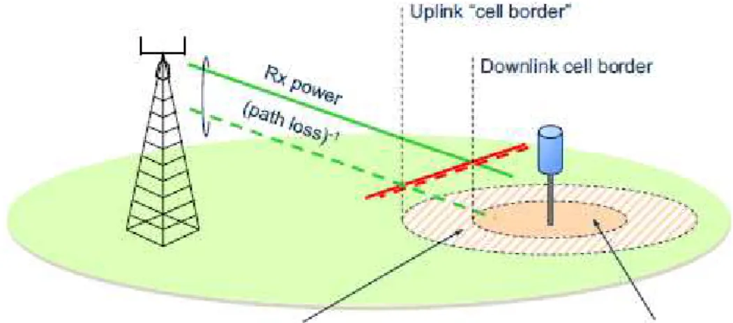
To avoid this undesirable effect and increase the efficiency of heterogeneous networks, an offset can be applied to the power measurements done by the terminals in order to compensate the difference in transmission power between different transmission points [DPS13]. This technique is known as Cell Range Expansion (CRE) [BLM+14] and leads to an extension in the coverage area of a low power node. It can be seen as an improve-ment but as it can be seen in figure 2.6, there will be higher interference levels from the macro TP in the new coverage area since the downlink signal from this TP will be received with a lower path loss fading. Downlink interference to CRE users can be overcome with resource partitioning techniques, where macro cells set aside certain restricted resources for the benefit of CRE users [BLM+14].
2.5. FEMTOCELLS AND HETEROGENEOUS NETWORKS 25
Figure 2.6: High Inter-cell Interference caused by the increase in coverage area of the low power cell. Adapted from [DPS13]
2.5.4 Interference Scenarios in Femtocell Networks
As it was explained in the previous section, if the femtocells are placed specifically in a hot spot (e.g. airports, universities, shopping malls), network gains can be obtained by deploying them without applying a range expansion. Since high capacity is desired in the network, the low power nodes are deployed in a co-channel scheme, meaning that they use the same portion of the frequency spectrum as the macro cells. This leads to inter-cell interference, so some interference management schemes have to be applied in order to mitigate interference. Interference in femtocell networks can be classified as:
Co-Tier Interference - Interference caused between eNBs of the same network that belong to the same tier, i.e. that have the same power and range class. The Quality of Service (QoS) requirement on the femtocell defines the threshold of the SINR needed to create a communication link [ZANM13]. SINR is defined as:
SIN R= S
N+I (2.1)
26 CHAPTER 2. STATE OF THE ART
an aggressor to the neighbouring FAPs. On the other hand, downlink co-tier interference is caused by a FAP, since its signal causes interference to the neighbouring UE. In closed access mode it can represent a bigger problem, since the terminals are served by the FAP they subscribed rather than by the strongest FAP.
Cross-Tier Interference - Interference caused between eNBs that belong to different tiers, i.e. have different power and range class. For example, cross tier uplink interference can happen when an UE that uses the services provided by a macro eNB is close to a femtocell operating in closed access mode, to which it does not have access; therefore having its transmission degraded by the strong signals transmitted by the femtocell UE. It can also be concluded that cross tier uplink interference can happen when a macrocell UE does its transmission near the FAP. On the other hand, downlink cross-tier interference happens when the FAP is located near the macro eNB and vice-versa. This kind of interference is more critical when femtocells operate in closed access mode, since in open access mode all the UEs automatically connect to the eNB that provides the strongest signal [ZANM13].
Interference Management in Femtocell Networks
The easiest way to deal with interference is the splitting of the frequency spectrum between adjacent cells. However this leads to the reduction of efficiency in the networks so in order to avoid using this technique, two distinct approaches can be employed to manage interference: avoidance and cancellation.
2.5. FEMTOCELLS AND HETEROGENEOUS NETWORKS 27
Interference Avoidance Schemes in Femtocell Networks
The Cooperative schemes presented in section 2.3 (e.g. CS/CB), avoid interference and can be employed on femtocell networks, if the FAP can apply spectrum sensing or if the macro cell eNB can provide the FAP with network information via a backhaul link. Some other interference avoidance schemes that do not involve coordination will be described in this section.
A time hopping scheme can be used on CDMA wireless systems to reduce cross-tier interference [ZANM13]. This scheme suggests that the transmission time period should be divided into multiple smaller portions, being each portion allocated to each user or to a group of users in the same cell, since CDMA systems allow multiple users to transmit at the same time without interfering with each other. No coordination is required between tiers, allowing each tier to divide the transmission time independently [ZANM13].
On Orthogonal Frequency-Division Multiple Access (OFDMA) or CDMA systems, power control schemes can be applied in the low power layer UEs to reduce the interference these can cause to macro cell edge users and eNB. Power control can be performed in Open loop or closed loop [SHLK12]. The open loop setting consists on the adjustment of the transmission power of the UE, based solely on estimations of the cross-tier interference to the macro cell eNB. The performance of this scheme is improved with the usage of the closed loop setting, where the macro cell Base Station (BS) also provides the FAP, via a backhaul link, its noise and interference level [ZANM13].
A particular spectrum splitting scheme can be applied in OFDMA wireless systems without leading to a waste in the network’s resources. This scheme consists on the division of the spectrum into two parts, one dedicated to the macro cell and one shared between the macro and the femtocell [SHLK12]. In this way, the macro cell can schedule cell edge users to the dedicated spectrum, avoiding the cross-tier interference they can cause.
Chapter 3
IB-DFE receiver model with
uplink signal diversity
CoMP was introduced in LTE advanced to improve the coverage in the border of the cells. In this chapter, it is presented how spatial diversity can improve the performance of the Multi Packet Detection (MPD) receiver presented in [GDBO12]. Power diversity schemes can improve the receiver performance, by determining the optimum offset between the UEs reception’s power.
3.1
LTE Femtocell Joint Processing
In order to study the benefits of CoMP transmission techniques, the proposed ar-chitecture employs a variation of the uplink MPD scheme used in [GDBO12]. This new scheme uses not only time diversity MPD but also spatial diversity in the reception of the uplink signal. The UEs transmit the packets using time slots, as before, but the signal is received by different eNB (e.g. femtocells) and is combined, providing the uplink signal with spatial diversity.
Even though the reception is done in different eNBs, it works as DAS deployment and allows the uplink signal processing to be done in a centralized way. This allows DC tech-niques to be used jointly with MPD to deal with packet errors and consequently improve signal reception. This CoMP technique is known as JP and diminishes the transmission degradation caused to cell edge users in dense networks by the harsh interference due to
30CHAPTER 3. IB-DFE RECEIVER MODEL WITH UPLINK SIGNAL DIVERSITY
Figure 3.1: Spatial diversity on the uplink
the transmission of nearby terminals.
The benefit that this technique brings to the transmitting devices depends greatly on the distance that the UE has to the multiple eNBs. The path loss attenuation that they have to the eNBs has to be sufficient to allow the reception of the signal with enough power to allow the decoding of the transmission in both eNBs. If this scenario is not achieved, providing the signal with time diversity instead of spatial diversity is more ben-eficial. Femtocell networks seem a good option to overcome this problem since there is a small distance and consequently a low path loss attenuation between the UE and the multiple reception points. A closed or hybrid access mode deployment is more adequate to implement this system because using femtocell networks can bring coordination problems due to the difficulty in controlling the amount of nodes connected to the network.
3.1. LTE FEMTOCELL JOINT PROCESSING 31
3.1.1 Network Architecture
The scenario analysed in this dissertation is the uplink communication scheme in a structured wireless system between a set of devices (UEs) and a network of LTE femto-cells, using a slotted data channel. UEs are low resource battery operated devices that use SC-FDE with Quadrature Phase Shift Keying (QPSK) modulation in the uplink trans-mission and femtocells are low power nodes that work as receivers. In every simulation a single small cell layer is considered (of femtocells), which would be part of an heteroge-neous layer network using exclusive frequency bands for each layer. These receiver nodes will be deployed in a DAS scheme, so although the reception of the uplink signal can be made in different eNBs, the processing of the received signals is done jointly at the receiver.
In this network, it is considered that all the packets associated to each uplink trans-mission have the same duration, which corresponds to a FFT block. Perfect channel estimation and synchronization between local oscillators is assumed. A cyclic prefix of dif-ferent length is added to each FFT block to compensate the difdif-ferent propagation times, so it is assumed that colliding packets arrive simultaneously. In every simulation of this chapter it is admitted that all the UEs transmit with the same power (except when power diversity is introduced) and that every UE present in the network has always a packet to transmit.
Multiple UEs can transmit in the same time slot to the same eNB and more trans-missions of the same uplink signal can be used to enhance the reception.
3.1.2 Mobile device association to the eNB
32CHAPTER 3. IB-DFE RECEIVER MODEL WITH UPLINK SIGNAL DIVERSITY
may be defined, so that the power received from the UE is enough to allow the decoding of the transmission in a scenario without interference. The power received at the antenna is obtained using:
Prx =Ptx+P L (dB). (3.1)
The path loss attenuation is a reduction of the power in the transmission caused by the distance to the receiver and by the propagation medium and is modeled using a simplified version of the Friis transmission equation given by:
P L=−10nlog10(d) (dB), (3.2)
where n is the path loss coefficient and d is the distance between the receiver and the transmitter. In wireless networks, the path loss coefficient value normally ranges from 2 to 4, where 2 is the Free space Path loss coefficient, which is a very optimistic approach. In the simulations in this dissertation it was consideredn= 2.8 to model the propagation conditions.
The UEs associate themselves with the eNB that receives their uplink transmission with more power, if the power received is higher than a pre-defined threshold. This is considered their primary eNB. Any UE that is not received with enough power at any eNB, cannot be handled unless temporal redundancy is used to enhance the reception. Therefore, for each eNB, there is a maximum range where the UEs can transmit above the power threshold. UEs that are outside of this range are treated as interference. In the CoMP scenario, if an UE is already associated to a primary eNB, it also associates itself to the second nearest eNB, where the original uplink transmission is received, despite the higher path loss their transmission presents to this receiver.
3.2
Receiver Structure
3.2. RECEIVER STRUCTURE 33
themselves in two categories: linear and iterative [LSW12].
3.2.1 Linear Receiver Model
In a Linear MUD, a linear transformation is applied to the soft outputs of the conven-tional detector in order to produce a new set of decision variables [LSW12]. This allowsP
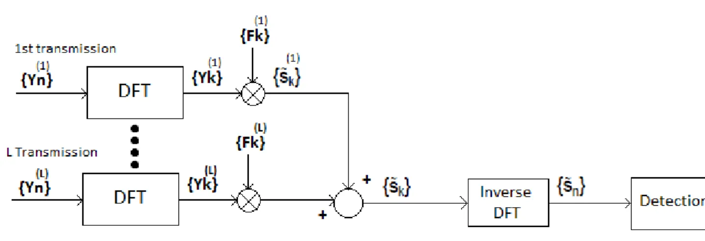
concurrent transmissions, for a minimum of L=P individual transmissions, if there is a perfect constant average power control at the reception [GDBO12]. The linear receiver can only solve collisions if the transmission of the colliding UEs is provided with time diversity. This happens when multiple copies of the same packet are transmitted over multiple time slots to the same eNB. A hybrid scheme, where linear MPD is combined with the DC technique, can be used to enhance data reception. In this case, the eNB signals the UEs to transmit their dataL > P times when the reception fails withLtransmissions. These situations are illustrated in figure 3.2 for the uplink transmission of two devices that are at the same distance from the receiver.
Figure 3.2: MPD and Hybrid MPD+DC technique usage to improve reception at the eNB
The content received at the base station is seen as a linear transformation of the modulated signal transmitted by the UE. Regarding the notation, A is used to denote a matrix, AT is the matrix transpose of A, AH is the complex conjugate transpose of
A. Considering the frequency domain samples of a data block from a UE p,{Sk,p;k =
34CHAPTER 3. IB-DFE RECEIVER MODEL WITH UPLINK SIGNAL DIVERSITY
[Sk,1, . . . , Sk,P]T. These P UEs transmit simultaneously during L slots. The received
content at the eNB after sampling, removing the cyclic prefix and applying a N-sized Discrete Fourier Transform (DFT) to the received signal is {Yk;k= 0, . . . , N−1}, where
Yk = [Yk(1), . . . , Yk(L)]. Every retransmission has a different channel realization due to the
physical properties of the propagation medium so Hk,p = [Hk,p(1), . . . , Hk,p(L)]. Furthermore
the channel noise has to be considered, since wireless networks are being modeled. It is going to be modeled as a Gaussian function and in this work it is considered that noise is heterogeneous (i.e. varies over different transmissions). So Nk = [Nk(1), . . . , N
(L)
k ]T
represents the channel noise in the frequency domain. The expression of the output in the receiver is given by:
YkT =HTkSk+Nk. (3.3)
Equation 3.3 can be expanded:
Yk(1)
.. .
Yk(L)
=
Hk,(1)1 . . . Hk,P(1)
..
. . .. ...
Hk,(L1) . . . Hk,P(L)
Sk,1
.. . Sk,P +
Nk(1)
.. .
Nk(L)
. (3.4)
In section 3.1.2 the path loss fading effect was described and defined as the main criteria to choose which devices are allowed to see its uplink signal treated at the eNB. The attenuation factor for UE p is denoted by |ξl,p|and the transmission channel Hk,p(l) is
replaced by |ξl,p|Hk,p(l) to account it. Considering that the path loss is constant for all the
retransmissions (i.e. its position does not change), equation 3.4 can be changed to:
Yk(1)
.. .
Yk(L)
=
|ξ1|Hk,(1)1 . . . |ξP|Hk,P(1)
..
. . .. ... |ξ1|Hk,(L1) . . . |ξP|Hk,P(L)
Sk,1
.. . Sk,P +
Nk(1)
.. .
Nk(L)
. (3.5)
Since SC modulation is being used, equalization is required to cope with the ISI caused by frequency selective fading. FDE is employed so the estimated data symbol is
˜
Sk,p = FTk,pYk. Fk,pT = [Fk,p(1), . . . , Fk,p(L)] are the feedforward FDE coefficients. A block
diagram of the linear receiver with FDE is presented in figure 3.3.
3.2. RECEIVER STRUCTURE 35
Figure 3.3: Linear Receiver Block Diagram
effects and the channel noise enhancement is the MMSE detection. Knowing that Γp =
[Γp,1 = 0, . . . ,Γp,p= 1, . . . ,Γp,P = 0]T, the mean square error of Sk,p for a single UE p is
[GDBO12]:
E
S˜k,p−Sk,p 2 = E h
FTk,pYk−Sk,p
2i
(3.6) = EhFTk,pHTk−Γp
Sk
2i
+EhFTk,pNk
2i
. (3.7)
ESkSHk
and ENkNHk
, represent the variance of the real and imaginary parts of
Sk,p and Nk,p, where ςN2 = diag(σ2
(1)
N , . . . , σ2
(L)
N ). In order to obtain the optimal Fk,p
coefficients under the MMSE criterion, the gradient of the Lagrange function is applied to equation 3.7. resulting [GDBO12]:
∇J =∇ E ˜
Sk,p−Sk,p
2
+ (γp−1)λp
, (3.8)
whereλdenotes the Lagrange multiplier and∇the gradient of the function. The Lagrange multipliers are constrained toγp−1 = N1 PNk=0−1
PL
l=1Fk,pl H
(l)
k,p−1 [GDBO12]. The optimal
Fk,p coefficients are:
Fk,p=
HHkHk+
σ2
N
σ2
S
−1 HHkΓp
1− 1 2N σ2
S
![Figure 2.1: OFDM sub-carriers, adapted from [TW11].](https://thumb-eu.123doks.com/thumbv2/123dok_br/16572449.738070/30.892.167.733.324.561/figure-ofdm-sub-carriers-adapted-from-tw.webp)