Design And Construction Of 300W Audio Power
Amplifier For Classroom
Shune Lei Aung, Kyaw Soe Lwin, Hla Myo Tun
Abstract: This paper describes the design and construction of 300W audio power amplifier for classroom. In the construction of this amplifier, microphone preamplifier, tone preamplifier, equalizer, line amplifier, output power amplifier and sound level indicator are included. The output power amplifier is designed as O.C.L system and constructed by using Class B among many types of amplifier classes. There are two types in O.C.L system _ quasi system and complementary system. Between them, the complementary system is used in the construction of 300W audio power amplifier. The Multisim software is utilized for the construction of audio power amplifier.
Keyword: O.C.L system, Class B amplifier, Multisim software
————————————————————
1. INTRODUCTION
An amplifier is an electronic device that increases the power of a signal. An audio amplifier is an electrical circuit and that produces sound louder. It does this by taking energy from a power supply and controlling the output to match the input signal shape but with larger amplitude. There are many forms of electronic circuits classed as amplifiers, from Operation Amplifier and Small Signal Amplifiers up to Large Signals and Power amplifiers. Amplifiers circuits form the basis of most electronic systems, many of which need to produce high power to drive some output device. Audio amplifier output power may be anything from less than 1 Watt to several hundred Watts. Radio frequency amplifiers used in transmitters can be required to produce thousands of kilowatts of output power, and DC amplifiers used in electronic control systems may also need high power outputs to drive motors or actuators of many different types. In the following discussion, the focus will be on power amplifier used in our daily life. Power amplifiers may be used in musical fields such as musical band, orchestra, karaoke rooms, cinemas, theatres and so on. Nowadays, listening to music is one of the ways for relaxation. Therefore, it is necessary to produce the good quality loud sounds. To produce loud sounds, amplifiers are essential things. There are four basic types of amplifier in electronic field: the voltage amplifier, the current amplifier, the Trans conductance amplifier, and the Trans resistance amplifier. The output power of the power amplifier is 300Watt. This audio power amplifier can be used in Classroom. Amplifiers can be thought of as a simple box or block containing the amplifying devices, such as a transistor, field effect transistor or op-amp which has two input terminals with the output signal being much greater than that of the input signal as it has been amplified. Audio Power Amplifier can be designed as
O.P.T system (Output transformer system)
O.T.L system (Output transformer less system)
O.C.L system (Output capacitor less system)
B.C.L system (Bridge capacitor less system)
O.P.T system is used to appear the sound from the output transformer to the output speaker. To get the good quality sound, push-pull system can be used in the output system. O.P.T system is constructed input, driver and output. In O.P.T system, low frequency response cannot easily get. And then, the size of the amplifier is big. O.T.L system is the sounds amplify system without output transformer. In this system, output capacitor is used instead of using output transformer. O.C.L system is used without output capacitor. Why O.T.L system cannot produce the good sound quality is because of using output condenser and the change of sound quality depending on the output condenser. B.C.L system is the system that two O.C.L combine with transistor or IC at the input stage. The output power of the B.C.L system is four times of the output power of O.C.L. Many types of amplifier classes are(i) Class A (ii) Class B (iii) Class C (iv) Class D (v) Class E (vi) Class F(vii) Class G(viii) Class H(ix) Class AB and so on. Class A Amplifier has low efficiency of less than 50% but good signal reproduction and linearity. Class B Amplifier is twice as efficient as Class A Amplifier with a maximum theoretical efficiency of about 70% because the amplifying device only conducts for half of the input signal. Class AB amplifier has an efficiency rating between that of Class A and Class B but poorer signal reproduction than Class A amplifiers. Class C Amplifier is most inefficient amplifier class as only a very small portion of the input signal is amplified therefore the output signal bears very little resemblance to the input signal. Class C Amplifiers have the worth reproduction. Class D operation makes the output circuit extremely efficient (around 90%) allowing high power output without the need for such high power transistors and elaborate heat sinks. Class D amplifier is very efficient class of amplifier suited to both high power audio and RF amplifiers and low power portable amplifiers. Class E and F amplifier is a highly efficient switching power amplifier. Class G amplifier aims that it reduces the amplifier power dissipation. Class G amplifier is very useful in large PA amplifiers.
FET is controlled by the input gate voltage and BJT is controlled by the input base current. The cost of the BJT is much lower cost than FET. The losses of the BJT are lower than FET. The trans conductance of the BJT is higher than FET. By using BJT, BJT can give low current and low voltage supply. BJT is good in amplification. By using FET, FET can give high current and high voltage supply. FET is not good in amplification. To get the high power, FET can be used.
————————————————
Fig1.1 Overall block diagram of audio poweramplifier
2. Proposed System Design
Microphone Preamplifier is to pre amplify the audio signals from the microphone or line (CD player, EVD player, etc...).Tone Preamplifier is to lift and cut the low frequency and high frequency of the signal. Equalizer is to adjust the balance between frequency components within an electronic signal then we need. Line Amplifier is to get the better sound force to the output power amplifier from the audio signals. Output Power Amplifier is to amplify the audio signals and to reach the necessary amount of watts.Sound Level Indicator is to indicate the volume of sounds.
2.1Microphone Preamplifier
Fig1.2 Circuit diagram of microphone preamplifier
The signal from the microphone is high. By usingthe small resistor value to get the smooth output signal.The feedback resistor can adjust how much gain needed.The signal from the tape or CD player is low. So, by using the large resistor value to get the smooth output signal.
Fig1.4 Simulation result of microphone preamplifier
2.2. Tone Preamplifier
Two types of tone preamplifier are passive tone preamplifier and active tone preamplifier.In passive tone preamplifier, the values of capacitors and resistors are not the same in each side of the circuit.In active tone preamplifier, the values of capacitors and resistors are the same in each side of the circuit. The output pin is connected to the tone RC network by making feedback.A human can hear the frequency range between 20Hz and 20 kHz.
Fig 1.5 Circuit diagram of tone preamplifier
Fig1.5 Simulation result of Tone Preamplifier
2.3. Equalizer
5 band channel is used in this equalizer.The 5-band frequencies are low, low-mid, mid, high mid and high frequency.The frequency ranges are 20Hz, 200Hz, 1000Hz, 2000Hz and 20000Hz. The more the bands are constructed, the less the frequency ranges are. And then, the capacitor values are small.
Fig1.6 Circuit diagram of 5 band equalizer
Fig1.7 Simulation result of 5 band equalizer for frequency 20kHz
Fig1.8 Simulation result of 5 band equalizer for frequency 20kHz
2.4. Line Amplifier
Before the signals from the microphone preamplifier, tone preamplifier and equalizer enter to the output power amplifier, the line amplifier drives the signals to have a better quality.
Fig1.9 Circuit diagram of Line Amplifier
Fig1.10. Circuit Diagram of output power amplifier
O.C.L system consists of differential input, Multiplier, Driver and output. Differential part is the input part and it is constructed by connecting the two transistors. Multiplier is to adjust the output voltage between speaker and supply. Driver is to get the good quality sounds at the output stage. Class B is constructed as output. Split face power supply is used in OCL system. After the signal are amplified by differential input, the signals are sent to the multiplifier. And then, these signals are sent to the output power amplifier as feedback. The Multiplier is used to get the equal current consumption at the
base of the driver’s transitors. Before the output power
amplifier amplifies , driver circuit is used. By using Class B, the effenciency is 75%.
3.Test and Result of Output Power Amplifier
Fig1.11Test of differential input , multiplier and driver circuit at the PCB
Fig1.12 Test of output power amplifier and power supply
The circuit materials are correctly setup on PCB. The power supply is giving by 60V dual supply to get the output power 300W. After the circuit are correctly setup, the output signal is needed to be check at the output. If the circuit are not correctly
by measuring the analog multimeter.
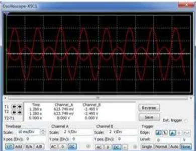
Fig1.13 Before giving the input signal
Fig1.14 After giving the input signal
Fig1.15Test of overall circuit of output audio power amplifier
After that, the multimeter is checked out again whether the AC voltage is produced or not. The gain of the output powet amplifier is 21dB.
5. Conclusion
Nowadays, amplifiers are very useful in human life,especially in entertainment field and educational field. To make good use of amplifiers, good-qualitied amplifiers are necessary. Many kinds of amplifiers from China and other countries can be found in the markets. However, some cannot be used for a long time as their quality is bad. For long-time use, self-designed and self-constructed amplifiers are safer. They can also be cheaper, more reliable and more effective.
R
EFERENCES[1] http://en.m.wikipedia.org/wiki/Audio_power_amplifier
[2] Introduction of audio power amplifier
[3] www.ti.com/amplifier
[4] www.learnelectronic .com
[5] transistor amplifier