IJCSI International Journal of Computer Science Issues, Vol. 8, Issue 3, No. 2, May 2011 ISSN (Online): 1694-0814
www.IJCSI.org 9
Fundamentals for the Automation of
Object-Relational Database Design
María Fernanda Golobisky1 and Aldo Vecchietti1
1 INGAR – UTN, Facultad Regional Santa Fe
Santa Fe, S3002GJC, Argentina.
Abstract
In the market there is a wide amount of CASE tools for the design of relational databases. Object-relational database management system (ORDBMS) emerged at the end of the 90’s to incorporate the object technology into the relational databases, allowing the treatment of more complex data and relationships than its predecessor. The design for this database model is not straightforward. Most of the works proposed in the literature fail because they do not provide consistent transformation formalization such that the mappings from the conceptual model to the logical schema can be automated to generate an ORDB design toolkit. This is one of the goals of this paper. For this purpose, UML class diagram metamodel for the conceptual design and SQL:2003 standard metamodel for logical schemas are considered. A characterization of the components involved in the ORDB design is made in order to propose mapping rules that can be further automated. The architecture of a CASE tool prototype is presented. Model Driven Architecture for software design and XML for the model definitions and transformations are employed.
Keywords: ORDBMS, SQL:2003, UML, database design, MDA, XML.
1. Introduction
Databases are a crucial component of information systems playing a strategic role in the support of the organization decisions; its design is essential to obtain an efficient and effective information system management. Database design process consists in defining the conceptual, logical and physical structure of the schema. The logical design of a database is obtained by transforming the conceptual one. For large projects conceptual database models are complex making its transformation a non-trivial task. In order to perform this work, it is important to count with a CASE tool based on a specific design methodology such that the designer can concentrate his work making decisions among different mapping possibilities the CASE tool has.
Nowadays, the relational databases are the most widely used. In this model, the conversion from the conceptual to the logical representation is directly made following perfectly defined steps [7]. Because of this, in the market there is a wide amount of CASE tools for relational databases, such as ToadTM Data Modeler [26], DB
Designer4 [8], DatabaseSpy [3], among others, which offer the possibility of drawing a conceptual model as an entity-relationship diagram and automatically transforming it into the logical schema.
instead of one based on SQL:2003 standard. Grissa-Touzi and Sassi [11] have proposed a tool to help in the design and implementation of an ORDB called Navig-tools from which the user can generate the modeling code in SQL3 language. The tool was based on the entity-relationship modeling. Most of the works presented in the literature fail because they do not provide consistent transformation formalization such that these mappings can be automated by a design process which can then be employed to generate a toolkit for ORDBMS design.
In this paper, a characterization of the components involved in the design of an ORDBMS is made, and mapping rules between them have been proposed. The idea behind this strategy is to generate a design process which can be further automated into a CASE tool. UML class diagram metamodel for the conceptual design and SQL:2003 standard metamodel for logical schemas are considered in this work. The architecture of a CASE tool prototype is presented which applies these metamodels and mapping functions. MDA (Model Driven Architecture) for software design and XML (Extensible Markup Language) for the definition and transformation models that MDA requires are used.
2. Object-Relational Design
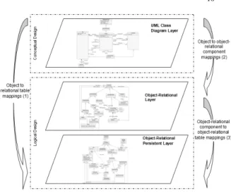
In the database design process different data models are used for the conceptual, logical and physical representation. At the conceptual design level a database independent model is generated identifying classes/entities, attributes and relationships which determine the semantic of data involved in the problem domain under study. In this work UML class diagrams are selected for this purpose. For the logical design, the element definitions composing the database schema must be made, in this sense, the SQL:2003 standard specifications are chosen for this work. Since the scope of this article does not include the physical representation of a database, no model is selected for it. As a first step in the characterization, three mapping layers are identified (Fig. 1) in the process of transforming UML class diagrams to ORDB schema, where two mapping steps are involved [9].
Fig. 1. Mapping layers involved in the ORDB design
The mapping layers are characterized as follows:
UML Class Diagram Layer: includes the conceptual model corresponding to the system requirements. It is composed of classes, associations, properties, association ends, etc. Different types of associations between classes can be established: aggregation, composition, association itself, hierarchy, association class.
Object-Relational Layer: is composed by the elements proposed by SQL:2003 standard: user-defined types, structured types, references, row types and collections: arrays and multisets. The definitions made on this tier do not allow the persistence of any object or “data” until tables to store them are created.
Object-Relational Persistent Layer: is composed by tables and typed tables of the objects defined in the previous layer. Some other “relational” elements such as constraints, domains, etc., are also components of this layer.
In Fig. 1 the mapping from a class diagram to a relational database was included in order to show the difference between the relational and the object-relational design. Due to SQL:2003 is a superset of the previous SQL standards it has the ability to support pure relational transformations (1) or object-relational transformations (2 and 3). From Fig. 1 can be observed that transformation from UML class diagrams to relational designs (tables) involves just one mapping step, while the mapping from UML class diagrams to object-relational schemas (typed tables) involves two step because of the intermediate layer.
2.1 Metamodels involved in the design
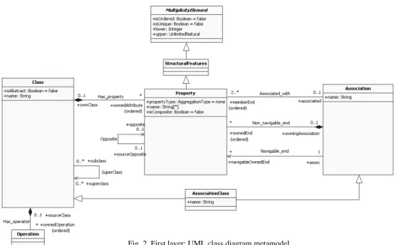
UML Class Diagram Metamodel
IJCSI International Journal of Computer Science Issues, Vol. 8, Issue 3, No. 2, May 2011 ISSN (Online): 1694-0814
www.IJCSI.org 11
2.0, based on Object Management Group [23][24]. A simplified version with the parts of the metamodel that are of interest for this work is used.
Class groups a set of objects with the same specifications of characteristics, restrictions and semantic. It has attributes represented by instances of
Property that are owned by the class, and moreover, it has Operations. Properties are Structural Features
which inherits from MultiplicityElement the capacity of defining inferior and superior multiplicity bounds indicating the cardinalities allowed for classes and associations. When a property is instantiated, the values of their attributes are related to the instance of a class and/or with the instance of an association type.
An Association specifies a semantic relationship that can occur between typed instances (in general Class
instances) and it has at least two ends called association ends that indicate the participation of the class in the association. The association ends can be navigables
(Navigable_end) or not navigables
(Non_navigable_end).
When a property represents an association end
connecting two classes its values are related with the instances of the other end. Association ends have a name (rolename) that identifies the function of the class in the association; when implemented it allows the navigation between objects. According to Rumbaugh, Jacobson, and Booch in [22] the rolename on the far side of the association is like a pseudoattribute of a class and have no independency apart from its association; it can be used as a term in an access expression to traverse the association. This concept is essential to represent associations and make its mappings, as it will be
explained later.
Finally, an AssociationClass is a statement of a semantic relationship between classifiers, with a set of characteristics that are owned by the relationship and not to the classifiers. The association class can be seen as an association that has class properties, or as a class that has association properties.
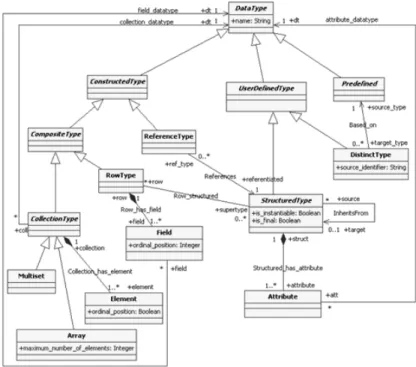
SQL:2003 Data Type Metamodel
Metamodels corresponding to the second and third layer were proposed by Baroni, Calero, Ruiz, and Abreu in [5]. The authors produced a SQL:2003 ontology based on the standard information and they separated their approach in two parts, one contains the aspects related to the data types (Fig. 3) and the other has information about the SQL:2003 schema objects: columns, domains, tables, constraints and other “relational” components corresponding to the persistent third layer (Fig. 4). These metamodels have been chosen because they are a state of the art representation containing all the elements needed for this work. Moreover, the data type metamodel is associated to the non-persistent second layer and the schema metamodel is related to the persistent third layer of the work presented in this paper.
In Fig. 3, it can be seen that there are three different kinds of Data Types: Predefined, User Defined Types
and Constructed Types.
Predefined or simple data types are those such as integer, number, character, boolean or large objects (LOBs). User Defined Types can be Structured Types
can be Reference Types that addresses the structured types; or Composite Types that are Collection Types
which can be Arrays or Multisets composed by
Elements. Row Types are another composite type which are in turn composed of Fields.
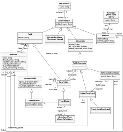
SQL:2003 Schema Metamodel
Fig. 4 shows that there are three different kinds of schema objects: Constraints, Domains and Tables. Table Constraints includes the definition of primary (PrimaryKey), unique (UniqueKey) and foreign keys (ReferentialConstraint). Tables can be Derived Tables
which are those generated through the execution of SQL commands (Views generation) or Base Tables simply known as “tables”. The latter can be specialized in
Typed Tables when they are generated from a Structured Type of the previous layer. Tables are composed by
Columns that can be defined over a Domain and can have some of the referential constraints before defined. SQL:2003 introduced new datatypes to the relational model, enriching it. That is why the transition from the conceptual to the logical model can not be made directly, such as in the relational case, in which an entity-relationship diagram or a class diagram becomes base tables.
3. Element Characterization
3.1 UML Class Diagram Layer
Fig. 5 shows UML class diagram representing the administration of purchase orders from a company. This model contains all the concepts needed to work out on this paper.
In this example, the business has stores in different locations having stock of the products it commercializes. Business customers can be persons or companies, and can be grouped into associations in order to get advantage of promotions. Every customer issues purchase orders about products they need.
Although the model is very simple, it contains different types of multiplicities and relationships needed to achieve the goals of this work.
IJCSI International Journal of Computer Science Issues, Vol. 8, Issue 3, No. 2, May 2011 ISSN (Online): 1694-0814
www.IJCSI.org 13
The formalization of these elements in order to its subsequent transformation into object-relational schemas is specified below.
Class
According to the UML metamodel, a class can be characterized by the following expression:
C = (name, isAbstract, properties, operations,
superclass) (1)
where isAbstract is a qualifier to indicate whether the class can be instantiated or not. Superclass corresponds to the name from which the class inherits properties and operations. Operations specify a set of methods the class
can execute. Properties represent a set of class attributes and association ends. Attributes can be simple or multivalued. The difference between them is given by the multiplicity. A simple attribute has multiplicity of 1, while a multivalued can go from 1 to n.
Taking this into account, an attribute can be formally Fig. 4. Third layer: SQL schema of the SQL:2003 metamodel
defined as:
A = (name, attributeType, multiplicity) (2) where name is the name assigned to the attribute;
attributeType is a predefined datatype as: integer, real, character, boolean, etc.; and multiplicity is the set of possible values an attribute can take.
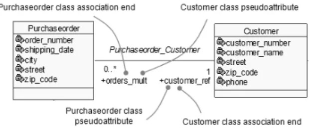
As was mentioned before, classes are linked to the association ends in two different forms. By one side, they define the class participation into the association, and by the other, they correspond to a pseudoattribute of the class. [22] states the association ends have several attributes, including a name and navigability. The “navigability” indicates whether the association end can be used to cross the association from one object to an object of the class on the other end. If the association ends is navigable, the association defines a pseudoattribute of the class that is in the opposite end of the association end (rolename) – i.e., the rolename can be similarly used to an attribute of the class to get values.Therefore, an association end in a class can have two different forms: as association end itself or as pseudoattribute (Fig. 6). These concepts are essential to map relationships between classes.
Fig. 6. Pseudoattributes and association ends
Association ends are formally defined as:
(3)
AEs = (name, isComposite, multiplicity, navigable,
endType) (3)
where name is the name assigned to the association end and is equal to the rolename; isComposite is a Boolean property that when true states that the association end is part of a composition relationship [24]; multiplicity is the set of possible values (0 to n) the association end can take; navigable is a property indicating whether is navigable or not; and endType is a property which can take 3 different values:
i). Aggregate: the end is the “whole” of an aggregation relationship
ii). Composite: the end is the “whole” of a composition relationship
iii).None: the end is not an aggregate or composite In a similar way, when the association ends are class
pseudoattributes are defined as follows:
PA = (name, isComposite, multiplicity,
navigable = ‘Yes’, endType) (4)
where name is the rolename assigned to the association end of the opposite side. The rest of the PA attributes are equal to the AEs.
Taking the expressions 1, 2, 3 and 4 into account, the formal definition of a class is given by:
C = (name, isAbstract, A, AEs, PA, O,
superclass) (5)
where name is the name assigned to the class; isAbstract
indicates whether the class can be instantiated or not; A
is the finite set of attributes; AEs is the finite set of the navigable association ends; PA is the finite set of the pseudoattributes; O is the finite set of operations; and
superclass is an attribute to indicate the name of the superclass when the class participates of a generalization-specialization relationship.
Using the Expression 5, the Purchaseorder class of Fig. 5 is defined as:
C = (name = ‘Purchaseorder’, isAbstract = ‘No’, A = (name = ‘order_number’, attributeType = ‘integer’, multiplicity = 1..1), A = (name = ‘shipping_date’, attributeType = ‘date’, multiplicity = 1..1), A = (name = ‘city’, attributeType = ‘string’, multiplicity = 1..1), A = (name = ‘street’, attributeType =‘string’, multiplicity = 1..1), A = (name = ‘zip_code’, attributeType = ‘string’, multiplicity = 1..1), AEs = (name = ‘orders_mult’, multiplicity = 0..*, isComposite = ‘No’, navigable = ‘Yes', endType = ‘none’), PA = (name = ‘customer_ref’, multiplicity = 1..1, isComposite = ‘No’, navigable = ‘Yes’, endType = ‘none’), PA = (name = ‘items_arr’, multiplicity = 1..20, isComposite = ‘Yes’, navigable = ‘Yes’, endType = ‘none’), superclass = ‘’)
Aggregation Relationship
An Aggregation Relationship is a binary association that specifies a whole-part type relationship, and it can be defined by the following expression:
Agg = (name, AEs) (6)
where name is the name assigned to the aggregation;
AEs are the association ends, navigables or not, that link the whole with the part. These association ends are defined like the Expression 3.
IJCSI International Journal of Computer Science Issues, Vol. 8, Issue 3, No. 2, May 2011 ISSN (Online): 1694-0814
www.IJCSI.org 15
Following the Expression 6, the aggregation relationship between Customer and CustomerAssociation can be defined as:
Agg = (name = ‘Customer_Custassoc’, AEs = (name = ‘custassoc_ref’, multiplicity = 1..1, isComposite = ‘No’, navigable = ‘Yes’, endType = ‘aggregate’), AEs = (name = ‘customers_arr’, multiplicity = 2..15, isComposite = ‘No’, navigable = ‘Yes’, endType = ‘none’))
Composition Relationship
A Composition Relationship is an association that specifies a whole-part type relationship, but this relationship is stronger than the aggregation due to the part life depends on the whole existence. The part must belong to a unique whole [22]. Furthermore, in a composition relationship the data flow generally in only one direction, from the whole to the part.
Taking this into account, a composition relationship is formally expressed as:
Cm = (name, AEs) (7)
where name is the name assigned to the composition;
AEs are the navigable association ends, corresponding to the part. These association ends are defined like the Expression 3. In respect of the multiplicity, the one of the whole will always be of 1, while the one of the part can take any value from 0 to n.
In accordance with the formalized in the Expression 7, the composition relationship definition is:
Cm = (name = ‘Purchaseorder_Orderlineitem’, AEs = (name = ‘items_arr’, multiplicity = 1..20, isComposite = ‘Yes’, navigable = ‘Yes’, endType = ‘none’))
Binary Association Relationship
Associations are links between two or more entities. A
Binary Association is a special one having exactly two association ends. It is particularly useful in order to specify navigability path among objects [22].
A binary association can be formally defined as follows:
BAs = (name, AEs) (8)
where name is the name assigned to the association; AEs
are the association ends, navigables or not, linking classes which particpates in the association. The association ends are defined like the Expression 3. The definition of the Purchaseorder_Customer
association is written as follows:
BAs = (name = ‘Purchaseorder_Customer’, AEs = (name = ‘customer_ref’, multiplicity = 1..1, isComposite = ‘No’, navigable = ‘Yes’, endType = ‘none’), AEs = (name = ‘orders_mult’, multiplicity = 0..*, isComposite = ‘No’, navigable = ‘Yes’, endType = ‘none’))
Association Class Relationship
An Association Class has both association and class properties. Its instances have attributes values and also references to the class objects linked by the association. It is not possible to link an association class to more than one association, because it contains a set of specific properties of the association to which it belongs [6]. As a consequence, the association class never participates of generalization-specialization relationships and can not be an abstract class. The introduced concepts related with the association class are depicted in Fig. 7.
Fig. 7. Association class
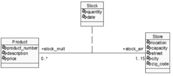
[22] states that an association class can be seen as a class with extra references to the classes participating in the association to which it belongs. According to [23] the multiplicity of the extra references is 1. Those references to the objects of the other classes become the association class pseudoattributes. Due to association class has no key it can not be accessed directly but through the other classes participating in the association. These classes relate to each other by means of the association class. Due to these characteristics, it is necessary to rectify its representation in order to automate the mapping. Fig. 8 shows the rectification, where stock_arr and stock_mult
are now association ends of Stock and new association ends (product_ref and store_ref) are added to Product
and Store to specify the extra references. With this representation the association class can be treated as a class having the particularities mentioned before.
Fig. 8. Association class treatment
In the rectified form, Product, Stock and Store have a complete set of association ends and pseudoattributes, which facilitate the mapping.
Therefore, an association class is defined as follows:
AC = (name, isAbstract = ‘No’, A, AEs, PA, O,
superclass = ‘’) (9)
are the navigable association ends that link the association class with the classes participating in the association to which it belongs; and PA is the finite set of the pseudoattributes of the association class.
According to Fig. 8 the association class is defined using the expressions 3, 4 and 9, as follows:
AC = (name = ‘Stock’, isAbstract =‘No’ A = (name = ‘quantity’, attributeType = ‘integer’, multiplicity = 1..1), A = (name = ‘date’, attributeType = ‘date’, multiplicity = 1..1), AEs = (name = ‘stock_arr’, multiplicity = 1..15, isComposite = ‘No’, navigable = ‘Yes’, endType = ‘none’), AEs = (name = ‘stock_mult’, multiplicity = 0..*, isComposite = ‘No’, navigable = ‘Yes’, endType = ‘none’), PA = (name = ‘product_ ref’', multiplicity = 1..1, navigable = ‘Yes’), PA = (name = ‘store_ref’, multiplicity = 1..1, navigable = ‘Yes’), superclass = ‘’)
Generalization-Specialization Relationship
A Generalization-Specialization Relationship is a taxonomic relationship between a more general element (called the superclass) and a more specific one (called the subclass). Subclasses inherit the properties from superclasses, but also have additional properties that are peculiar to it [22].
In order to specify a relationship of this type when the class is defined it must be specified the superclass from which it inherits (Expression 1).
3.2 The Object-Relational Layer
For the characterization of the SQL:2003 metamodel components the elements closely related to the mappings needed for this work are considered. These elements are: Distinct type
Row type Reference type
Collection types: Arrays and Multiset Structured types
The definitions made over this layer do not allow the persistence of any object until table creation.
Distinct Type
A Distinct Type is the simplest kind of user-defined type. It is defined over a predefined data type.
DT = (name, type) (10)
where name is the name assigned to the distinct type; and type is a predefined data type such as integer, real, character, LOB, etc., over which is defined.
Row Type
A Row Type is defined as a set of pairs:
RT = (Fi : DTi) (11)
where Fi = F1, F2;…, Fn is the name of a field in the row type; and DTi = DT1, DT2,…, DTn is a predefined data
type such as integer, real, character, LOB, etc. Reference Type
A Reference Type is a datatype that contains a value that reference an object corresponding to a structured type. This datatype is defined as:
Ref = Ref(ST) (12)
where ST indicates the referenced structured type. Collection Type
Array
An Array is an ordered collection of elements of any admissible type, except another array, and it has a maximum length. An array is defined as follows:
Arr = (eType, MQ) (13)
where eType is the type of element of the array and it can be a row type, a reference type, an structured type or a predefined type; and MQ is the maximum number of elements of the array.
Multiset
A Multiset is an unordered collection of elements of any admissible type. It has no a maximum length specified. A multiset is defined as:
Mult = (eType) (14)
where eType is the type of element the collection can have and it can be a row type, a reference type, an structured type or a predefined type.
Structured Type
The essential component of SQL:2003 that supports the object orientation is the Structured Type. The “structured” word distinguishes it from the distinct type that is also a user defined type, which is based on the predefined types and does not have an associated structure.
Structured types have attributes of different types, behavior, and can be inherited by other structured types, between other characteristics.
Note that SQL:2003 structured type is the equivalent concept of a UML class.
The structured type can be defined as:
ST = (name, A, M, P) (15)
where name is the name assigned to the structured type;
A is a finite set of attributes; M is a finite set of methods; and P is a finite set of properties.
IJCSI International Journal of Computer Science Issues, Vol. 8, Issue 3, No. 2, May 2011 ISSN (Online): 1694-0814
www.IJCSI.org 17
A = (name, type) (16)
where name is the name assigned to the attribute; and
type can be any of the standard defined types: predefined, structured, distinct, row and/or reference types.
If it is a collection type, it is defined like in the expressions 13 and 14.
With respect to the properties of the Expression 15, they are formally defined as:
P = (inheritFrom, isInstantiable, isFinal) (17) where inheritFrom is a property that indicates the name of the structured type corresponding to the supertype from which it inherits; isInstantiable specifies whether the type can have instances or not; and isFinal indicates whether the type can have subtypes or not.
3.3 The Object-Relational Persistent Layer
The object-relational persistent layer is not a physical layer but is a logical representation of how data are represented. It takes the form of a table in the object-relational technology as well as in the object-relational system. Unlike the latter, in the object-relational databases the columns are not restricted to predefined data types. As was mentioned above, only the typed tables of the SQL:2003 metamodel are taken into account since they are employed to store objects of a specific structured type.
Typed Tables
A Typed Table can be defined as:
TT = (name, ST, R) (18)
where name is the name assigned to the table; ST is the structured type from which is created the table; and R is the finite set of restriction definitions such as primary, unique and/or foreign key, not null and/or check type restrictions.
Typed tables provide persistence and identity to objects created from a structured type. Moreover, they automatically map structured type attributes into typed table columns.
The primary and unique key definitions must be considered at this point because they define the access paths to the objects; the query optimizer can take advantage to execute a query from these definitions.
4. Transformations to obtain
Object-Relational Schemas
For object-relational databases there is not a consensus in a technique or methodology to transform conceptual model into a logical schema. This section propose all
mappings needed to obtain an object-relational database schemas complying with SQL:2003 specifications. These are formalized such that they can be performed without ambiguity and in an automatic way. For the sake of clarity, this section is split in 2 parts:
Mappings from the UML Class Diagram to Object-Relational layer
Mappings from the Relational to Object-Relational Persistent layer
Transformations between the layers are formalized by means of mapping functions of the f:AB form. A
Mapping function f from A to B is a binary relationship between A and B. It can be seen as a transformation of the elements of A into elements of B. Therefore, every element of A becomes exactly one element in B.
4.1 Mappings from the UML Class Diagram to Object-Relational Layer
UML class formal definition contains all the elements required to be transformed into the middle layer (object-relational layer). Having this concept in mind, mappings to transform components from UML class diagrams into object-relational layer are centered in the following elements:
Attributes Pseudoattributes Operations
Generalization-Specialization Relationships Classes
Association Class Attribute Transformation
Class attributes are transformed into structured type attributes by means of the following mapping function:
f:AC(name, attributeType, multiplicity)
AST(name, type) (19)
For the sake of clarity in the previous mapping function, class attributes and the structured type attributes are indicated with the subscript “C” and “ST”, respectively. When the attribute multiplicity is 1, the attributeType of the class will match with the type of the structured type. SQL:2003 standard uses the collection types to represent attributes with multiplicity greater than 1, which may optionally have an upper and lower limit indicating the number of possible values. However, collection types can not be used arbitrarily, but they must fulfill some conditions to be correct. These restrictions apply not only to represent multivalued attributes, but also to extend to other kinds of transformations.
If the attribute multiplicity is 1 it is a single attribute, then, the mapping function is the following:
f:AC(name, attributeType, 1..1)
AST(name, type = eType)
If lower and upper limits are well known, then an array should be used with a specific length; it eventually it may grow if it is necessary.
f:AC(name, attributeType, 1..n)
AST(name, type = Arr(eType, n)) (21)
In the previous expression Arr stands for array;
eType represents the attribute type of the element composing the array and n its length.
If the upper and lower limits are not defined, a multiset must be used because this collection type does not limit the values to store.
f:AC(name, attributeType, 1..*) AST(name,
type = Mult(eType))
(22 ) In the previous expression Mult stands for multiset;
eType corresponds to the element type composing it. In all the previous cases the type of eType matches the type of attributeType of the class.
Pseudoattribute Transformation
When a class participates in a relationship (association, aggregation, composition, association class) and it has navigable ends, these can be considered as pseudoattributes of the class presented in the opposite side of the relationship. These ends involve a multiplicity, a navigability and a type, among others properties.
Pseudoattributes become crucial in the transformation of class relationships. Mapping functions are generated with the objective of preserving relationship semantic, as follows:
If the pseudoattribute is not composite (isComposite = ‘No’) and its endType property is “none” or
“aggregate”, it is transformed using references, having into account its multiplicity.
o If the multiplicity is 1, it is transformed into a reference type single attribute.
f:PA(name, multiplicity = 1..1,
isComposite = ‘No’, navigable = ‘Yes’, endType = ‘none’/‘aggregate’) AST(name, type = Ref(OST))
(23)
where OST is the opposite structured type of the relationship.
o If the multiplicity is defined and it has a maximum of n, it is transformed into an array of reference types of length n.
f:PA(name, multiplicity = 1..n,
isComposite = ‘No’, navigable = ‘Yes’, endType = ‘none’/‘aggregate’) AST(name, type = Arr(Ref(OST), n))
(24)
o If the multiplicity is undefined (specified by an *) it is transformed into a multiset of reference types.
f:PA(name, multiplicity = 1..*,
isComposite = ‘No’, navigable = ‘Yes’, endType = ‘none’/‘aggregate’) AST(name, type = Mult(Ref(OST)))
(25)
If the pseudoattribute is composite (isComposite = ‘Yes’) and its endType property is “none”, then the pseudoattribute represents the association end corresponding to the part of a composition relationship, and it is transformed into a structured type embedded into the structured type of the whole. It must also be considered the multiplicity of the pseudoattribute, as follows:
o If the multiplicity is of 1, the pseudoattribute is transformed as an attribute of the structured type corresponding to the part.
f:PA(name, multiplicity = 1..1, isComposite = ‘Yes’, navigable = ‘Yes’, endType = ‘none’) AST(name,
type = OST)
(26)
o If the multiplicity has a maximum of n, it is transformed into an array of length n of the structured type of the part.
f:PA(name, multiplicity = 1..n, isComposite = ‘Yes’, navigable = ‘Yes’, endType = ‘none’) AST(name,
type = Arr(OST, n))
(27)
o If the multiplicity is undefined (*), it is transformed into a multiset of structured types.
f:PA(name, multiplicity = 1..*, isComposite = ‘Yes’, navigable = ‘Yes’, endType = ‘none’) AST(name,
type = Mult(OST))
(28)
For the previous cases, OST is the opposite structured type of the relationship corresponding to the part of the composition relationship.
Pseudoattributes whose eType property is “composite”
represent the whole of a composition relationship. In agreement with the definition the whole of a composition is not navigable. Therefore, pseudoattributes of type before mentioned are not converted into the object-relational layer.
Operation Transformation
IJCSI International Journal of Computer Science Issues, Vol. 8, Issue 3, No. 2, May 2011 ISSN (Online): 1694-0814
www.IJCSI.org 19
treatment is performed in a simple manner because its analysis goes beyond the scope of this article. Having this issue into account, the UML operations are transformed into methods of the structured types by means of the following function:
f:O M (29)
where O is a finite set of operations; and M is a finite set of methods.
Generalization - Specialization Relationship Transformation
In the UML class diagram as well as in the object-relational layer generalization - specialization relationships are specified by means of qualifiers (isAbstract, superclass, inheritFrom, isInstantiable). The transformation of this relationship type is made using those ones. The mapping function defined to the generalization-specialization relationship is:
f:C(name, isAbstract = ‘No’,… , superclass = ‘superclass_name’) ST(name,…, isInstantiable = ‘Yes’, inheritFrom = ‘supertype_name’)
(30)
Class Transformation
Classes of the UML diagram of the conceptual design are mapped into a structured type the object-relational technology.
f:C(name, isAbstract, A, AEs, PA, O, superclass)
ST(name, isInstantiable, A, M, inheritFrom) (31) The transformation of each class component was previously described. Note that attributes and pseudoattributes of a class are transformed into attributes of the structured type.
Association Class Transformation
The mapping of an association class is similar to the one defined for a class. Hence, attributes, pseudoattributes and operations are transformed in the same way. The difference is on the fact that an association class can not participate of generalization-specialization relationships.
f:AC(name, A, PA, O) ST(name, A, M) (32) 4.2 Mappings from the Object-Relational to the Object-Relational Persistent Layer
Once the object-relational elements are obtained typed tables must be defined in order to provide persistence to the objects. For this purpose, every structured type of the object-relational layer is transformed into a typed table of the object-relational persistence layer. This mapping function is defined as follows:
f:ST TT(name, ST) (33)
where name indicates the name assigned to the typed table; and ST specifies the structured type which origins it.
To complete the mapping of this layer, the designer must enter additional information which is not included in the metamodels of the previous ones. The first case is related with table restrictions (primary key, unique key, not null restrictions, check type restrictions, etc.), which do not have an equivalent neither UML class diagram nor object-relational layer. The other one corresponds to the transformation of generalization-specialization relationships from the object-relational layer to typed tables. In the latter, the user must choose the mapping from the three different possibilities that exist:
Flat Model: this model includes the definition of a single table for the whole hierarchy. It must create a typed table for the supertype, with the
substitutability property that enables the storage of subtypes in the same supertype table.
Vertical Partition: in this mapping a typed table for every class in the hierarchy is created. The
substitutability property is removed, so only the appropriated structured types can be stored in those tables.
Horizontal Partition: in this transformation typed tables for subtypes are created, translating all supertype attributes to them. The substitutability property is removed.
5. Automation of Database Design Process
The automation proposal presented in this paper is based on MDA and XML. The Model Driven Architecture [21] was originated in response to the new technology advances, diversity of system exploitation platforms and business model continuous changes. MDA decouples the functional specification from the implementation specification of that functionality for a specific platform. It proposes a development process based on the realization and transformation of the models. The principles on which MDA is based are abstraction, automation and standardization. Those are the main reasons to select MDA for the ORDB automation process.
The models used by MDA are classified into:
Platform Independent Models (PIM): are models with a high level of abstraction, independents of any implementation technology. The UML class diagram metamodel is the PIM of this work.
Platform Specific Models (PSM): combine
specifications of the platform independent model with the details of a specific platform. The PSM of this work is related with SQL:2003.
starts from the requirements of an application (Platform Independent Model) which is then transformed into one or more Platform Specific Models which are finally converted into code (Fig. 9).
Fig. 9. Development process in MDA
On the other hand, XML has also a number of advantages for application development that justifies its use for the automation process of ORDB schemes. These are:
It is a formal and concise language, from the point of view of the data and the way of storing them. It is extensible, which means that once the structure
of a document was designed and put into production, it is possible to extend it with the addition of new tags, allowing the model evolution. It is expressive, its files are easy to read and edit. If
a third person chooses to use a document created in XML, it is easy to understand its structure and process it, which improves the compatibility among applications.
There are commercial and free tools that facilitate its implementation, programming and the production of different systems.
The XML schema definition language [26] has become a dominant technology to describe the type and the structure of XML documents. This capability makes it appropriate for the definition of the metamodels used in this work. XML schemas provide the basic infrastructure for building interoperable systems because they provide a common language for the XML document description. The specification of the XML transformations (XSLT) defines a language for expressing rules which allows transforming an XML document into another. XSLT [14] has many of the traditional constructors of the programming languages, including variables, functions, iterators and conditional sentences, so XSLT can be thought as a programming language. Furthermore, XSLT documents are also useful as general purpose language to express transformations from an XML schema to another. In fact, the use of XSLT documents can be imagined as an XML translation engine, so this technology was selected for this, for the implementation of mapping rules.
5.1 Transformation Methodology Architecture
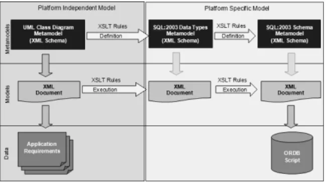
The architecture to perform the model transformation is
depicted in Fig. 10.
Fig. 10. Transformation methodology architecture
The architecture is based on different abstraction levels [10]:
Metamodel Level: contains XML schemas generated for the three metamodels used for the transformations: UML class diagramas, SQL:2003 Data Types and SQL:2003 Schema. Besides, XSLT transformation rules between the XML schemas are defined in this level.
Model Level: contains the XML documents fulfilling the XML Schemas defined in the metamodel level. The first XML document complying with the UML metamodel represents the hierarchical and structured information of the application. Mappings from one XML document to another are performed executing the XSLT rules defined in the metamodel level.
Data Level: this level contains the input and output of the model level. The UML class diagram corresponding to the application requirements is the input while the output is the code of the object-relational database schema.
IJCSI International Journal of Computer Science Issues, Vol. 8, Issue 3, No. 2, May 2011 ISSN (Online): 1694-0814
www.IJCSI.org 21
6. Conclusions
Nowadays, there are several commercial tools which automate relational database design (ToadTM Data Modeler, DB Designer4, DatabaseSpy), but it is not the case for object-relational ones. The reason for this situation is that does not exist a standard methodology accepted in the database community. This paper describes a method to overcome this gap. First, three mapping layers for the object-relational database design process were defined: UML class diagram layer, object-relational layer and object-object-relational persistent layer. This is a novel aspect of this work because it represents a difference respect of other works proposed in the literature. A metamodel is used and adapted for each layer, for the conceptual design, the UML class diagram metamodel; for the logical design, the SQL:2003 metamodel, split in two parts: datatypes and schema. A detailed description of the elements composing the metamodels was made superseding other works proposed in the open literature. A key issue in the characterization of the UML class diagram is the distinction of association ends participating as pseudoattributes of the classes. This concept facilitates the mapping definition for associations between classes. Mapping functions between metamodels were proposed and formalized by means of f:AB type expressions. In this article, the most common transformation set between the UML class diagrams and the object-relational databases is presented.
The automation of the ORDB design process is addressed with an architecture based on the MDA specification and the XML technology. MDA is selected because is the indicated technology for model-based software design. The platform independent model (PIM) is represented by the UML class diagram metamodel and platform specific models (PSM) are composed by the SQL:2003 metamodels. The architecture has different levels of abstraction: metamodels, models and data. These specifications separate the functionalities facilitating the transformation rule generation.
The architecture implementation was made using XML technology: XML schemas for the metamodel definitions, XSLT rules for transforming the schemas, and XML documents that represent the structured information of the application complying with the XML schemas. The use of the XML technology facilitates the reading, understanding, modifying, testing and fixing the tool for ORDB design.
For future work, properties and the impact that present the inclusion of the behavior in the first steps of the design, and its next mapping to the object-relational model, will be investigated with the objective of completing the design and the case tool implementation.
References
[1] Altova GmbH (2006). Altova MapForce 2007 User and Reference Manual. Revised May 5, 2005, from http://www.altova.com/download/2006/MapForcePro.pdf [2] Altova GmbH (2007). Altova XMLSpy 2008 Enterprise
Edition User and Reference Manual. Revised September
5, 2006, from http://www.altova.com/download/2006/XMLSpyPro.pdf
[3] Altova GmbH (2010). Altova DatabaseSpy 2010. http://www.altova.com/databasespy.html
[4] Arango, F., Gómez, M. C., & Zapata, C. M. (2006). Transformación del modelo de clases UML a Oracle9i® bajo la directiva MDA: Un caso de estudio. DYNA, Vol. 73 (149), (pp. 166-179).
[5] Baroni, A. L., Calero, C., Ruiz, F., & Abreu, F. B. (2004). Formalizing object-relational structural metrics. 5a Confer^encia da APSI.
[6] Booch, G., Rumbaugh, J., & Jacobson, I. (1999). The Unified Modeling Language. User Guide. Addison-Wesley Professional.
[7] Elmasri, R., & Navathe, S. (2006). Fundamentals of Database Systems, 5th Edition. Addison-Wesley.
[8] fabFORCE (2003). DB Designer 4 Online Documentation. Fabulous Force Database Tools. Revised 2003, from http://www.fabforce.net/dbdesigner4/
[9] Golobisky, M. F., & Vecchietti, A. (2005). Mapping UML class diagrams into object-relational schemas. In
Proceedings of the Argentine Symposium on Software Engineering (ASSE 2005), 34 JAIIO, (65-79 pp). [10]Golobisky, M. F., & Vecchietti, A. (2008). A flexible
approach for database design based on SQL:2003.
Proceedings of the XXXIV Conferencia Latinoamericana de Informática CLEI 2008 (pp. 719-728).
[11]Grissa-Touzi, A., & Sassi, M. (2005). New approach for the modeling and the implementation of the object-relational databases. World Academy of Science, Engineering and Technology. Vol. 11 (pp. 51-54).
[12]ISO/IEC 9075-1 (2003). Information technology - Database languages – SQL- Part 1: Framework (SQL/ Framework), International Organization for Standardization.
[13]ISO/IEC 9075-2 (2003). Information technology - Database languages – SQL- Part 2: Foundation (SQL/Foundation), International Organization for Standardization.
[14]Kay, Michael (2007). XSL Transformations (XSLT), Version 2.0. Revised January 23, 2007, from W3C Recommendation, http://www.w3.org/TR/xslt20.
[15]Liu, C., Orlowska, M. E., & Li, H. (1997). Realizing object-relational databases by mixing tables with objects.
OOIS, (pp. 335-346).
[16]Marcos, E., Vela, B., & Cavero, J. M. (2003). A methodological approach for object-relational database design using UML. Software and Systems Modeling, 2(1), 59-72.
[17]Marcos, E., Vela, B., Cavero, J. M., & Caceres, P. (2001). Aggregation and composition in object-relational database design. In Albertas Caplinskas and Johann Eder (Ed.) 5th Conference on Advances in Databases and Information Systems ( pp. 195-209).
[18]Melton, J., & Simon, A. R. (2002). SQL:1999-Understanding Relational Language Components. Morgan Kaufmann.
[19]Melton, Jim (2003). Advanced SQL:1999: Understanding Object-Relational and Other Advanced Features. Morgan Kaufmann.
[20]Mok, W. Y., & Paper, D. P. (2001). On transformations from UML models to object-relational databases.
[21]Mukerji, J., & Miller, J. (2003). MDA Guide Version 1.0.1. Object Management Group. Revised June 12, 2003, from http://www.omg.org/cgi-bin/doc?omg/03-06-01. [22]Rumbaugh, J., Jacobson, I., & Booch, G. (1999). The
Unified Modeling Language. Reference Manual. Addison-Wesley.
[23]OMG (2005). Unified modeling language: Superstructure, Version 2.0. OMG Final Adopted Specification. Retrieved
July 2005, from http://www.omg.org/spec/UML/2.0/Superstructure/PDF
[24]OMG (2006). Unified modeling language: Infrastructure, Version 2.0. OMG Final Adopted Specification. Object Management Group. Retrieved July 2005, from http://www.omg.org/spec/UML/2.0/Infrastructure/PDF [25]Quest Software (2010). ToadTM Data Modeler 3. Quest
Software, Inc. http://www.casestudio.com/enu/default.aspx
[26]W3C (2004). XML Schema. Revised October 28, 2004, from XML Schema Working Group Public Page,
http://www.w3.org/XML/Schema
M.F. Golobisky obtained his PhD degree in Engineering, major in Information Systems Engineering, in 2009, at Universidad Tecnológica Nacional, Facultad Regional Santa Fe, Argentina. She is Professor at this University and research fellow of CONICET.