B. FRANCOIS C. SAUDEMONT S. LABIOD
LAboratoire d’étude et de Modélisation en Electrotechnique (LAMEL) Université de Jijel, BP 98, Ouled Aissa, Jijel, Algérie
Regular paper
Solving Harmonics Elimination Problem in Three-Phase Voltage-controlled Inverter using Artificial
Neural Networks
Journal of Electrical Systems
A novel concept of application of Artificial Neural Networks (ANN) for generating the optimum switching functions for the voltage and harmonic control of DC-to-AC bridge inverters is presented. In many research, the neural network is trained off line using the desired switching angles given by the classic harmonic elimination strategy to any value of the modulation index. This limits the utilisability and the precision in other modulation index values. In order to avoid this problem, a new training algorithm is developed without using the desired switching angles but it uses the desired solution of the elimination harmonic equation, i.e. first harmonics are equal to zero. Theoretical analysis of the proposed solving algorithm with neural networks is provided, and simulation results are given to show the high performance and technical advantages of the developed modulator.
Keywords: Inverter, Harmonics Elimination, Neural Networks, Gradient Descent Algorithm..
1. INTRODUCTION
In recent years, switch-mode DC-to-AC power inverters are used in AC motor drive and uninterruptible AC power supplies (UPS) etc [1-3]. In most cases, low distortion sinusoidal output voltage waveforms are required with controllable magnitude and frequency. Moreover, the power semiconductor switching speed has improved dramatically. Modern ultra-fast insulated gate bipolar transistors (IGBTs) demand switching frequency as high as 5 kHz. The DSP-based PWM algorithm practically fails on this region where ANN-based PWM can possibly take over [3]. Note that ANN has inherent learning capability that can give improved precision by interpolation unlike the standard look-up table method and Space Vector Modulation. The application of ANN is recently growing in power electronics and drives area. A feed forward ANN basically implements nonlinear input-output mapping. The computational delay of this mapping becomes negligible if parallel architecture of the network is implemented by an Application-Specific Integrated Circuit (ASIC) chip. The optimal switching pattern Pulse Width modulation (PWM) strategies constitute the best choice for high power, three-phase, voltage-controlled inverters and for fixed frequency, fixed-voltage UPS systems. For any chosen objective function, the optimal switching pattern depends on the desired modulation index. In the existing practice, the switching patterns are pre-computed for all the required values of this index, and stored in look-up tables of a microprocessor-based modulator [4]. This requires a large memory and computation of the switching angles in real time is, as yet, impossible. To overcome this problem, attempts were made to use approximate formulas, at the expense of reduced quality of the inverter voltage [5-7].
equation to define the harmonic-elimination switching angles [6] and by using piecewise constant orthogonal functions [16].
In this paper, a new training algorithm is developed without using the pre-computed switching angles. But, we use the application of the output of the ANN in the nonlinear elimination harmonic equation. The desired output of this equation is known (the first equation equal the modulation index and the lasts equal to zero to eliminate this harmonics). The complete set of solutions to the non linear equations is found using the back propagation of the errors between the desired harmonic elimination and the non linear equation systems using the switching angle given by the ANN. Illustrative examples are given to demonstrate the feasibility of the proposed method.
2. HARMONICS IN ELECTRICAL SYSTEMS
One of the biggest problems in power quality aspects is the harmonic contents in the electrical system. Generally, harmonics may be divided into two types: 1) voltage harmonics, and 2) current harmonics. Current harmonic are usually generated by harmonics contained in voltage supply and depends on the type of the load such as resistive load, capacitive load, and inductive load. Both harmonics can be generated by either the source or the load side. Harmonics generated by load are caused by nonlinear operation of device, including power converters, arc-furnaces, gas discharge lighting devices, etc. Load harmonics can cause the overheating of the magnetic cores of transformer and motors. On the other hand, source harmonics are mainly generated by power supply with non-sinusoidal voltage and /or non-sinusoidal current waveforms. Voltage and current source harmonics imply power losses, Electro-Magnetic Interference (EMI) and pulsating torque in AC motor drives [13-15]. Any periodic wave form can be shown to be the superposition of a fundamental and a set of harmonic components. By applying Fourier transformation, these components can be extracted. The frequency of each harmonic component is a multiple of its fundamental [4]. There are several methods to indicate the quantity of harmonics contents. The most widely used measure is the total harmonics distortion (THD), which is defined in terms of the magnitudes of the harmonics, Hn at pulsation
n
ω
, where ω is the pulsation of the fundamentalcomponent whose magnitude is H1 and n is an integer [7][16]. The THD is mathematically given by
2 2
1
n n
H THD
H
∞
=
=
∑
(1)vdc
n va
S1 S2
3. SELECTIVE HARMONIC ELIMINATION (SHE) STRATEGY
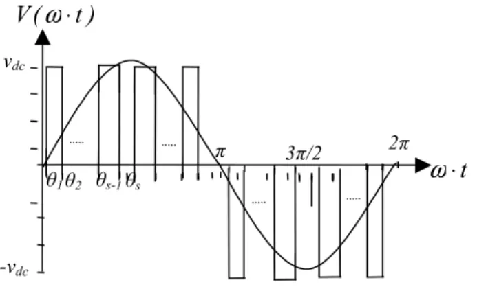
Various objective functions can be used in the optimal control of an inverter. For the described study, the classic harmonic elimination strategy was selected. It consists in determining
s
optimal switching angles. The primary angles are limited to the first quarter cycle of the inverter output line voltage (phasea
) Fig.1. Switching angles in the remaining three quarters are referred to as secondary angles. The full-cycle switching pattern must have the half-wave and quarter-wave symmetry in order to eliminate even harmonics. Hence, the secondary angles are linearly dependent on their primary counterparts Fig. 2. The resultant optimal switching pattern yields a fundamental voltage corresponds to a given value of the modulation index, whereas(
s
−
1
)
low-order, odd, and triple harmonics are absent in the output voltage [8][11-12].vdc
-vdc
t
⋅
ω
π 2π
θ1 θ2 θs-1θs
)
t
(
V
ω
⋅
3π/2
Fig. 2: Output Voltage Waveform of a three-level inverter angle SHE-PWM.
Note that, each of the waveforms have a Fourier series expansion of the form [8]
( )
1 1,3,5, 14 1
( ) sin( ) 1 cos( )
∞ +
= =
= × − θ
π
∑ ∑
"s i dc
i
n i
V
V wt nwt n
n (2)
Where 0≤ θ ≤ θ ≤1 2 "≤ θ ≤ πs 2, the Fourier series is summed over only the odd harmonics.
Again, the aim here is to use these switching schemes to achieve the fundamental voltage. And to eliminate the fifth, seventh and 11th harmonics, etc, for those values of the modulation index
(
)
(
= 1 4 dc π)
m m H v .
The harmonic elimination technique is very suitable for inverters control. By employing this technique, the low THD output waveform without any filter circuit is possible. Switching devices, in addition, turn on and off only one time per cycle. Fig. 2 shows a general quarter symmetric inverter waveform.
The expression of the amplitude of the fundamental and all harmonics content are given as:
( )
1( )
14
( ) 1 cos
0
+
=
θ = π = − θ
∑
dc s
i n
n n i
i
v
for odd n h
H n with h n
where:
dc
v
is the DC voltage supply,s
is the number of switching angles andθ
i is the optimized harmonic switching angles.In the three-phase inverter, the aim is to use this switching scheme to achieve the fundamental voltage and eliminate the fifth, seventh and 11th harmonics, etc (n=1, 5, 7, 11, 13, 17, 19,"). For those values of the modulation index
m
, the switching angles θ θ1, 2,",θs are chosen tosatisfy
( )
( )
( )
11 1 2
1
2 1 2
1
1 2
1 cos( )
cos( ) cos( )
0
cos(5 ) cos(5 ) 1 cos(5 )
0
cos( ) cos( ) 1 cos( )
+
+
+
= θ − θ + + − θ =
=
= θ − θ + + − θ
= θ − θ + + − θ =
" " #
"
s
s s
s
s
n s
m h
h
h n n n
(4)
These equations are nonlinears, contain trigonometric terms and are transcendental in nature. Consequently, multiple solutions are possible. A Newton Raphson method has to be first applied to obtain a linearized set of equations [8]. The solution of these equations is achieved by means of the Gauss-Jordan iterative method. In order to obtain convergence with this method, the starting values of switching angles should be close to the exact solution. A great deal of effort has been spent in this technique. However after a great computational time and efforts, no optimal solution is usually reached and convergence problems are highly arising especially when the number of equations is increased [4][16].
The application of the ANN to obtain the switching angles can be introduced to overcome the aforementioned difficulties.
4. ARTIFICIAL NEURAL NETWORKS
x1 w11
w12
w1h
v11
v12
v1p
vh1
vh2
vhp
1
2
h
1
2
p
y1
y2
yp
1
2
n x2
xn
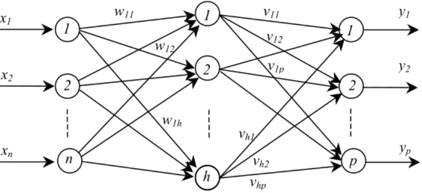
Fig 3: A typical multilayer ANN.
The model of an artificial neuron can be represented by the op-amp summer-like configuration shown in Fig. 4. It can be described by the following equation:
0 1
( )
=
= σ +
∑
k i ii
y w w x (5)
where,
y
: the output of the neuron,i
x
: the ith input to the neuron,i
w
: the ith connection weight,0
w
: the bias weight,( )
⋅
σ
: the transfer function of the neuron,k
: the number of connections with the neurons in the preceding layer.σ
(.)
1
x1
xk
w0
w1
wk
y
The input signals x x1, 2,", xk are normally continuous variables. Each of the input signals flows
through a gain or weight. The weights can be positive or negative corresponding to acceleration or inhibition of the flow of signals. The summing node accumulates all the input weighted signals and then passes to the output through the transfer function which is usually nonlinear, such as sigmoid, inverse-tan, hyperbolic or Gaussian type. The sigmoid transfer function used in output layer has the form given by:
1
1 ( )
1 −α
σ =
+ x
x
e (6)
Where
α
is the coefficient or gain which adjusts the slope of the function that change between the two asymptotic values (0 and +1). The sigmoid function is nonlinear, monotonic, and differentiable and has the largest incremental gain at zero signals.In the hidden layer, the Gaussian transfer function has been used
2
2( , )
−
− σ
σ = v
x w
x w e (7)
5. DIRECT SUPERVISED TRAINING OF ANN FOR SHE
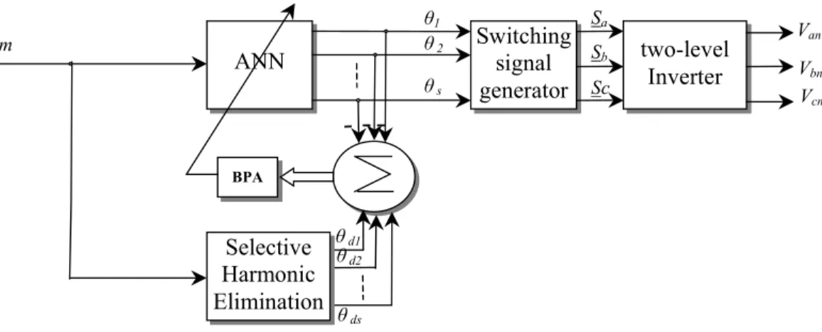
Back Propagation training Algorithm (BPA) is most commonly used in feed forward ANNs. When a set of input values are presented to the ANN, step by step calculations are made in the forward direction to drive the output pattern. A cost functional given by the squared difference between the net output and the desired net output for the set of input patterns is generated and this is minimized by gradient descent method altering the weights one at a time starting from the output layer [10-12][18] (Fig.5).
ANN
BPA
Switching signal generator
two-level Inverter
m
θ1
θ 2
θ s
Sa
Sb
Sc V
cn Vbn Van
Selective Harmonic Elimination
θ d1
θ d2
θ ds
Fig. 6 ANN set for the Selective Harmonic Elimination
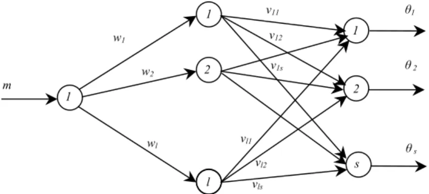
In this section, an ANN with a single input neuron fed by the modulation index, l hidden neurons and
s
outputs each representing a switching angle are used. The network was training using the Back Propagation Algorithm (BPA). The training data extracted from the optimal switching angles, designated by θ1 to θs as functions of the modulation index m. This set of angles isrequired to eliminate the 5th, 7th and 11th harmonics, etc, given by equation (4). The outputs of the ANN shown in Fig. 6 are given by
(
)
1 2
1
, , 1, ,
=
θ = σ σ =
∑
"l
i ij j
j
v m w i s (8)
The BPA is given by:
Step 1: Define the nodes
W
of the Gaussian functions. Random initialization of the weightsV
.Step 2: present at the input of the network a value of the modulation index
m
,Step3: calculate the output of the neurons of the hidden layer and the output layer;
_ Hidden layer: σ2( ,m W) with =
[
1 2 "]
T l
W w w w ,
l
: number of the neurons in the hidden layer._ Output layer: θ = σ1
(
V⋅σ2(
m W,)
)
, with size V( ) ( )
= s l, .Step 4: Normalize the outputs of the neuron network between 0 and π / 2, one should multiply the
output vector by π / 2, i.e. θnor = θ× π2.
Step 5: Calculate the total error E= θ − θd nor, and 2
(
) (
T)
d nor d nor
E = θ − θ θ − θ , θd is given by
the Newton Raphson Algorithm.
Step 6: Back propagate this error on the network using gradient descent algorithm
2
1 2 ∂
= − η
∂
new old
v
E
V V
V (9)
∂θ
= + η
∂
new old
v
V V E
V (10)
m
w1
w2
wl
v11
v12
v1s
vl1
vl2
vls
1
2
l
1
2
s
θ1
θ 2
θ s
Step 7: Adapt the weights recursively by
(
)
( )
(
)
1
, , 2
1
1 , 2
1
, ,
1,...,
' , ,
1,..., =
= + η ⋅δ ⋅σ
=
δ = σ ⋅σ =
∑
new old
i j i j v i j
l
i i k k
k
V V m W
with
i s
E i V m W and
j l
(11)
Step 8: Repeat steps 3 to 7 until obtaining the desired precision.
6. INDIRECT SUPERVISED TRAINING OF ANN FOR SHE
In this case, the neural network is trained to generate the switching angles in a way to eliminate the first harmonics without the knowledge of the desired switching angles given by the Newton Raphson method. The problem which arises in this indirect learning paradigm is that the desired outputs of the ANN, i.e. optimal angles, are unknown. However, the application of the desired outputs on the nonlinear equation system (equation (4)) is known, i. e., to place the first harmonics at zero by approximating the output voltage by the fundamental one.
To avoid this problem, we will insert in series with the ANN the equivalent nonlinear system equations (equation (4)). Therefore, instead of the minimization of the error between the switching angles given by the ANN and the wished switching angles often unknown, we will minimize the error at the output of the nonlinear system equation of the harmonics to be eliminated.
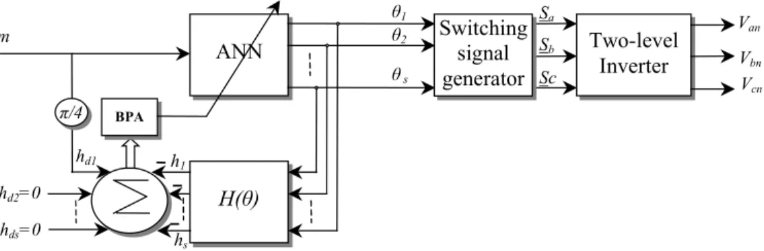
Fig. 7 shows the diagram of the indirect training strategy of artificial neuron networks used for harmonics elimination. When the desired precision is obtained the output of the ANN is used to generate the control sequence of the inverter.
ANN
H(θ)
BPA
Two-level Inverter
m
hd1
hd2=0
hds=0
π/4
θ1
θ2
θ s
h1
hs
Vcn Vbn Van
Switching signal generator
Sa Sb
Sc
Fig. 7 Indirect Training of ANN for Selective Elimination Harmonic.
Step 3: calculate the output of the neurons of the hidden layer and the output layer;
- Hidden layer: σ2( ,m W) with =
[
1 2 "]
T l
W w w w ,
l
: number of the neurons in thehidden layer.
- Output layer: θ = σ1
(
V⋅σ2(
m W,)
)
, with size V( ) ( )
= s l, .Step 4: Standardize the outputs of the network of neuron between 0 and π / 2, one multiplies the
output vector by π / 2, i.e., θnor = θ× π 2.
Step 5: Apply the ANN outputs to the nonlinear system equation H
( )
θ (equation (4)).Step 6: Calculate the total error E =Hd
( )
θ −H( )
θ , and(
( )
( )
)
(
( )
( )
)
2= θ − θ T θ − θ
d d
E H H H H .
Step 7: Back propagate this error on the network using gradient descent algorithm
2
1 2 ∂
= − η
∂
new old
v
E
V V
V (12)
∂ ∂θ
= + η
∂θ ∂
new old
v
H
V V E
V (13)
with,
( )
( )
( )
1 1 2 1 1 2 1 1 2sin( ) sin( ) sin( )
sin(5 ) sin(5 ) sin(5 )
sin( ) sin( ) sin( )
+
+
+
θ − θ − θ
θ − θ − θ
∂ = −∂θ
θ − θ − θ
" " # # " s s s s s s H
n n n
(14)
Step 8:Adapt the weights recursively by
(
)
( )
( )
(
( )
)
(
)
1
, , 2
1 0
1
1 0
1 , 2
1
, ,
1 ( ) sin ( )
1,..., , 1,..., ' , + = =
= + η ⋅δ ⋅σ
δ = − ⋅ ⋅ ⋅ ⋅θ
=
=
δ = δ σ ⋅σ
∑
∑
new old
i j i j v i j
s i i
k l
i i i k k
k
V V m W
with
E i n k n k i
i s
and
j l
V m W
(15)
Step 9: Repeat steps 3 to 8 until obtaining the desired precision.
After the termination of the training phase, the obtained ANN can be used to generate the control sequence of the inverter as shown in Fig. 8.
ANN
Two-level
Inverter
m θθ1
2
θ s V
7. SIMULATION RESULTS
The indirect training strategy of ANN (with l =201, σ =v 1 500, η =v 0.2 and ∆ =w 0.005) for SHE (with s=5) was evaluated for the range of the modulation index, with excellent results in all cases. Fig. 9 shows the obtained switching angles for various values of modulation index (m∈
[ ]
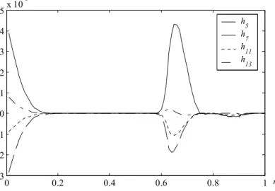
0,1 with ∆ =m 0.01) without BPA (Fig. 8).It is clear that the 5th, 7th, 11th and 13th harmonics are strongly suppressed and their magnitudes are negligible relatively to the fundamental component (Fig. 10-11). The higher harmonics are also low which contributes to a high quality of the output voltage.
0 0.2 0.4 0.6 0.8 1
0.2 0.4 0.6 0.8 1 1.2 1.4 1.6
an
g
le
θ1
θ2
θ3
θ4
θ5
m
Fig. 9: Switching angles after training phase.
0 0.2 0.4 0.6 0.8 1
0 0.1 0.2 0.3 0.4 0.5 0.6 0.7 0.8
h
1
h
d1
Fig. 10 represents the relationship between the amplitude of the fundamental load voltage
h
1 and the modulation index, which must be linear for a good modulation method. It can be observed that the proposed method, after training phase, has a good relationship betweenh
1 andm
. Another important aspect, to be considered in the evaluation of this modulation method, is the total harmonic distortion (THD) of the load voltage (Fig. 12).0 0.2 0.4 0.6 0.8 1
-3 -2 -1 0 1 2 3 4 5x 10
-3
h
5
h
7
h
11
h
13
m
Fig. 11: Harmonic contents for various values of modulation index
0 0.2 0.4 0.6 0.8 1
0 0.02 0.04 0.06 0.08 0.1 0.12 0.14
THD
m
Fig. 12: Load voltage THD for different modulation indexes.
8. CONCLUSION
requires neither high computing power nor specialized ANN hardware. The main drawback of this technique lies in the training phase, since; this phase is quite complex and time consuming. Fortunately, the training is executed off-line. After training phase, the connection weights can be stored on a memory for further use.
In the indirect supervised scheme, the ANN is trained without using the desired switching angles what makes it possible to solve the problems of the traditional methods. By adding in series the harmonic elimination equations and using the fact that the desired output of these equations are nulls. Only the first are corresponding to the fundamental is equal to the modulation index
m
.The given simulation results proving the feasibility of the proposed technique.9. REFERENCE
[1] M. Kojima, K. Hirabayashi, Y. Kawabata, E. C. Ejiogu and T. Kawabata, “Novel Vector Control System Using Deadbeat Controlled PWM Inverter With Output LC Filter”, IEEE Transactions on
Industrial Applications, Vol. 40, No. 1, January/February 2004, pp. 132-169.
[2] P. Z. Grabowski, M. P. Kazmierkowski, B. K. Bose and F. Blaabjerg, “A Simple Direct-Torque Neuro-Fuzzy Control of PWM-Inverter-Fed Induction Motor Drive”, IEEE Transactions on Industrial
Electronics, Vol. 47, No. 4, August 2000, pp. 863-870.
[3] J. O. P. Pinto, B. K. Bose, L. E. B. da Silva and M. P. Kazmierkowski, “A Neural-Network-Based Space-Vector PWM Controller for Voltage-Fed Inverter Induction Motor Drive”, IEEE Transactions
on Industrial Applications, Vol. 36, No. 6, November/December 2000, pp. 1628-1636.
[4] S. sirisukprasert, J. S. Lai and T. H. Liu, “Optimum Harmonic Reduction With a Wide Range of Modulation Indexes for Multilevel Converters”, IEEE Transactions on Industrial Electronics, Vol. 49, No. 4, August 2002, pp. 875-881.
[5] S. Jian, S. Beineke and H. Grotstollen, “Optimal PWM based on real-time solution of harmonic elimination equations”, IEEE Transactions on Power Electronics, Volume: 11, Issue: 4, July 1996 Pages:612 - 621
[6] S. R. Bowes and P. R. Clark, “Simple Microprocessor Implementation of New Regular-Sampled Harmonic Elimination PWM Techniques”, IEEE Transactions on Industrial Applications, Vol. 28, No. 1, January/February 1992, pp. 89-92.
[7] J. N. Chaisson, L. M. Tolbert, K. J. Mckenzie and Z. Du, “A Unified Approach to Solving the Harmonic Elimination Equations in Multilevel Converters”, IEEE Transactions on Power Electronics,
Vol. 19, No. 2, March 2004, pp. 478-490.
[8] T. H. Abdelhamid, “Application of Artificial Neural Networks to the Voltage Inverters Controlled by Programmed PWM Control Techniques”, Proceedings of the IEEA’97,International Conference 7-9 Dec.1997, Batna University, Algeria. pp. 165-168.
[9] Y. J. Wang and R. M. O’Connell, “Experimental Evaluation of a Novel Switch Control Scheme for an Active Power Line Conditioner”, IEEE Transactions on Industrial Electronics, Vol. 50, No. 1, February 2003, pp. 243-246.
[10] D. Daniolos, M. K. Darwish and P. Mehta, “Optimised PWM inverter Control using Artificial Neural Networks”, IEE 1995 Electronics Letters Online No : 19951186, 14 August1995, pp. 1739-1740.
[13] O. Bouhali, E.M. Berkouk, C. Saudemont and B. François, “A Five level Diode Clamped Inverter with self-stabilization of the DC-Link Voltage for Grid Connection of Distributed Generators”, IEEE
International Symposium on Industrial Electronics : ISIE 2004, May 3-7, 2004, Ajaccio, France.
[14] O. Bouhali, E.M. Berkouk, C Saudemont and B. François, “Direct Modulation of Electrical Conversion for a Multilevel Inverter including stabilization of the unbalance DC-Link Voltage”, IEEE Power
Electronics Specialist Conference : PESC 2004, June 24-25, 2004, Aachen, Allemagne.
[15] Q. Song, W. H. Liu, MC Wong, Y.D. Han, “A Novel Universal Space Vector Modulator for Multilevel Voltage-Source Inverters”, 29th Annual Conference of the IEEE Industrial Electronics Society,
Roanoke, Virginia, USA, November 2nd – 6th 2003.
[16] J. Nazarzadeh, M. Razzaghi, and K. Y. Nikravesh, “Harmonic Elimination in Pulse-Width Modulated Inverters using Piecewise Constant Orthogonal Functions”, Electric Power Systems Research, Vol. 40, 1997, pp. 45-49.
[17] B. Francois, “Orthogonal Considerations in the Design of Neural Networks for Function
Approximation”, Mathematics and Computers in Simulation, Vol.41, 1996, pp. 95-108.
[18] L. A. Cabrera, M. E. Elbuluk, and D. S. Zinger, “Learning Techniqus to Train Neural Networks as a State Selector for Inverter-Fed Induction Machines using Direct Torque Control”, IEEE Transactions