Effects of Thermomechanical Treatment on the Occurrence of Coincident Site Lattice
Boundaries in High Strength Low Alloy Steel
Renato Soares de Castroa,b, Ricardo Artur Sanguinetti Ferreiraa*, Igor Rafael Vilarouco Pedrosaa,b,
Yogendra Prasad Yadavaa
aDepartment of Mechanical Engineering, Federal University of Pernambuco – UFPE, Recife, PE, Brasil bDepartament of Mechanical, Federal Institute of Education, Science and Technology of
Pernambuco – IFPE, Recife, PE, Brasil
Received: November 28, 2012; Revised: June 7, 2013
Many studies propose thermomechanical routes to improve HSLA (high strength low alloy) steels
by microstructural modiication but ignore the study of occurrence of CSL boundaries. The occurrence of these special boundaries is inluenced by thermomechanical treatment in which the modiication of misorientation proile is related with the increase of Σ3 and Σ11 boundaries and inhibition of Σ5 Σ7 and Σ9 ones. The formation of Σ3 boundaries, beneicial to improve strength, is highly stimulated by
this treatment in which deformation plays an important role in the development of CSL boundaries.
Keywords: HSLA steel, thermomechanical treatment, acicular ferrite, coincident site lattice
1. Introduction
In recent years studies have led attention to CSL (Coincident Site Lattice) boundaries, mainly to investigate the inluence of special boundaries in metallic material
properties1-3. The development of special boundaries has
been frequently achieved by annealing treatments. Many of these studies are concerned to stainless steel3, where low Σ boundaries should be beneicial to minimize crack
corrosion mainly due to the low energy of those boundaries. Otherwise low attention has been taken to the occurrence of CSL boundaries in HSLA (High Strength Low Alloy Steel) steel. Many authors have investigated the relationship
between thermomechanical treatment and improvement
of mechanical properties4-6 relating this improvement to
the presence of particular microstructure, such as acicular ferrite. HSLA steels with acicular microstructure achieve
good properties combination, such as high strength,
excellent toughness and superior fatigue behavior7,5. Many studies propose thermomechanical routes to improve microstructural changes in HSLA steel but ignore the
occurrence of CSL boundaries. This work investigates the misorientetion boundary profile and occurrence of CSL boundaries in HSLA X80 steel submitted to thermomechanical treatment for increasing toughness by microstructural modiication.
2. Experimental Procedure
The material used in this experiment was an HSLA steel composed of (wt. %) C 0.07 - S 0.004 - Al 0.036 - Si 0.27 - P 0.016 - Ti 0.018 - V 0.022 - Cr 0.017 - Mn 1.55 - Ni 0.01 - Cu 0.01 - Nb 0.069 - Mo 0.19. Samples were produced in the form of strips with dimensions of 100 × 9.5 × 6.0 mm. The
faces to be rolled were inished with 6.0 mm thickness and tolerance of ± 0.2 mm.
Samples were heated in electrical furnace until 950 °C, maintained for 900 s and then hot rolled at non recristalization temperature of austenite by a duo rolling cylinder at a strain rate of 1,8 s–1. The rate in applied strain
varied from 10% to 35%.
SEM images were obtained from cross sections of
samples submitted to standard metallographic preparation
and inally etched with nital at 3%. EBSD analysis were performed in a JSM-5900LV JEOL microscope with Channel 5 software (HKL Company) for data acquisition and data analysis. Samples for EBSD were sanded in 1500 MESH sandpaper and polished with diamond paste. To eliminate possible surface deformations produced by grinding and mechanical polishing, samples were inally polished in colloidal silica of 1 µm for 7.2 × 10³ s. Micro
hardness Vickers test was carried out with load of 0.1 kg for 15s. For each sample ive measurements were performed on the central axis of the specimen.
3. Results and Discussions
As-received steel had a microstructure with
well-deined polygonal ferrite grains with average grain size of 3.6 ± 0.3 µm as shown in Figure 1a. After thermomechanical
treatment, the predominance of polygonal ferrite in microstructure was eliminated. The sample deformed at 10% presented the morphology of a chaotic structure with lamellar and acicular aspects (Figure 1b), which literature has reported as acicular ferrite8-10. In samples deformed
at 25% and 35% (Figures 1c, d) predominant presence of acicular ferrite was more evident, characterized by bundles of ferritic laths interwoven in a chaotic distribution.
The change from polygonal to acicular microstructure
increases strength and toughness in steel11 due to iner
grain size, higher density of dislocations and presence of subunits in acicular ferrite7. Results of Vickers hardness test
in Table 1 conirm the trend of increasing yield strength due
to increasing hardness in treated samples when compared
to the as-received material.
Predominance of acicular ferrite, in specimens more intensely deformed, can be attributed to plastic deformation of austenite below non recristalization temperature4 which
for this steel is around 1100 °C. The high density of dislocations in deformed austenite seems to be beneicial to the formation of acicular ferrite to the detriment of the nucleation of bainite. Plastic deformation of austenite suppresses the formation of the bainitic structure from the grain boundaries and favors the formation of acicular
structure stimulated by intragranular nucleation4.
Ot can be observed in the grain boundaries map
(Figure 2) the evolution from a regular and well-designed grain shape microstructure in as-received steel (Figure 2a) to a iner and less regular one in the sample submitted to thermomechanical treatment (Figure 2b). It can be seen, from histograms in Figure 3a, b, that as-received steel has a misorientation frequency close to normal distribution, while for sample deformed at 10% an increase of frequency at low
angles (2 ° to 15 °) as well as at high angle (50 ° to 60 °) is
observed (Figure 3b). This tendency is maintained in other treatment conditions, with the occurrence of the highest frequency of low angle in the sample deformed at 25%. This result, reinforced by SEM images, shows that change
in misorientation proile is highly inluenced by plastic deformation, which also encourages austenite nucleation and formation of subunits in acicular ferrite6.
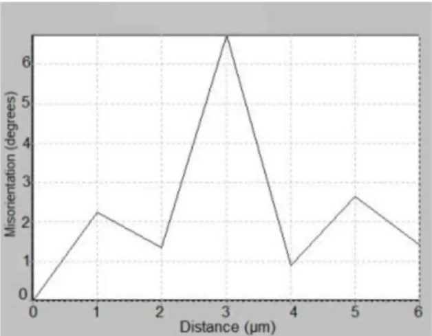
The increase of frequency in low angle indicates the refinement of the structure12 with the presence
of crystallographic packages of acicular ferrite with misorientation degree between them of about 5°, and
subunits with misorientation angle5,12 from 1° to 2°. It
was also identiied changes in hardness, crescent with the level of deformation (Table 1) that, in steels with acicular microstructure, can be attributed to the high presence of
misorientation angle12 up to 3°.
Thermomechanical treatment increased the occurrence of CSL boundaries, particularly Σ3 type, in all conditions of
treatment, as detected in (Figure 3d) when compared to the as-received material (Figure 3c). The Σ3/total CSL rate of
28.7 % in the as-received steel rises to 43.3% in the sample subjected to 10% strain (Table 1) and remains at high level
Figure 1. Micrographs of as-received steel and treated samples: (a) as-received (b) deformed at 10%, (c) deformed at 25%, (d) deformed at 35%.
Table 1. Frequency of occurrence of CSL boundaries and hardness Vickers for various deformation conditions.
Def. (%) CSL boundaries type (%)
and Hardness (HV)
*CSL Σ3 Σ3/CSL Hardness
As-received 12.1 3.5 29 265
10 16.2 7.0 43 313
35 12.9 5.7 44 403
for greater deformations, indicating that the mechanism of deformation is an important factor in shaping Σ3 boundaries.
It was detected some relationship between the proile of disorientation and the occurrence of CSL boundaries. Considering that in CCC lattices the Σ3 boundaries are
generated by the rotation angle of 60° of the plane <111>,
it is expected that, due to Σ3 increase, there should be
an equivalent increment of frequency in misorientation proile close to 60°. In the as-received steel, misorientation frequency between 58-60° corresponds only to 5.6% of
total CSL boundaries while in the sample deformed at 10% (where there is high increase of Σ3 boundaries) this
frequency rises to 11.4%, computing a variation of 5,8% (Table 2). Samples subjected to greater deformation also presented increases of Σ3 boundaries and misorientations
around 60 ° when compared to non treated samples. As for Σ3 boundaries, modiication of quantity of other Σ boundaries can be detected by changes of misorientation
proile. Table 2 shows the variation of occurrence of CSL boundaries and respective modiication of misorientation
Figure 2. Grain boundaries (in black) and CSL boundaries (in color): (a) as-received steel (b) steel submitted to thermomechanical treatment deformed at 35%.
proile around speciic angle for each Σ-symmetry. The
increase of frequency of Σ3 and Σ11 boundaries, as well
as the reduction of Σ5, Σ7 and Σ9 boundaries detected in
10% deformed samples, compared to not treated one, have respective variations on misorientation proile (Table 2). This modiication was also detected for 25% and 35% deformation conditions.
Variation in misorientation profile can be clearly detected with the comparison between histograms of Figure 3a and Figure 3b. The reduction of Σ5, Σ7 and Σ9 boundaries is veriied by means of decrease in the
frequency of misorienteation degree from 33.5° to 41.5° in misorientation proile, while the increase of boundaries of Σ11 type is revealed with the increasing frequency
misorientation around 50° (Figure 3b).
According to Arain3 and Gadzer et al.13, the increasing
fraction of special boundaries has signiicant inluence on the properties of the material. Low angle boundaries, as well as CSL’s with low Σ value are inactive and more
resistant to intragranular fracture than high energy random
boundaries14. Thus it is expected that the sample subjected
to thermomechanical treatment with deformation of 25% shows the highest resistance to intragranular fracture since it combines a high fraction of Σ3 boundaries (Table 1) with
low occurrence of contours with Σ > 29. Suzuky et al.1 found
not only the importance of low Σ boundaries in metallic
materials, but also measured their limits of resistance by means of a method to evaluate the resistance of CSL boundaries. They compared the values of grain boundary fracture strength, in a Cr-Ni alloy, for different types of CSL
boundaries and achieved that Σ3 type presented the greatest
value of strength, while Σ5, Σ9, Σ7 and Σ11 had decreasing
values in this order.
Considering the results of Suzuky1, the significant
increase from 3.5% to 7.1% of Σ3 boundaries, in sample
deformed at 10% (Table 1), should increase the strength of the material. However, the decrease of the amounts of Σ5, Σ7, Σ9 boundaries, weaker than Σ3, can decrease this beneit
which was not totally evaluated by that author.
The inding of high fracture strength in Σ3 boundaries
for Cr-Ni alloys1 reinforces the positive inluence of the
thermomechanical treatment on HSLA steels. Once applied, this treatment caused signiicant increase in Σ3 boundaries
in all samples, when compared to the as-received material. It was also observed, in intragranular regions of treated
samples, the presence of twin events (Figure 4). This phenomenon is a favorable factor to the formation of special type of boundaries2 and separates regions of symmetric
misorientations, named as twins.
Some studies related to the occurrence of CSL boundaries show the effect of annealing treatments to stimulate or inhibit the formation of special boundaries15,16.
However no studies were found reporting the effect of thermomechanical treatment on the formation of CSLs in HSLA steels. Randle16, when investigated the mechanism
of formation of CSL boundaries stimulated by annealing,
presented a model called “Σ3 regeneration” which shows
that the mobility of CSL boundaries, causes interactions among these types of boundaries which, depending on
its nature, results in predominant Σ3 boundaries type. According to this model, a Σ3 boundary when meeting a Σ9, also highly presented in cubic lattices, originates a new Σ3 boundary, just as meeting a Σ9 and Σ27 also originate a Σ3.
This phenomenon would explain the fact that Σ3 boundaries
are highly present in treated samples.
Despite that the treatment applied here does not involve annealing process to allow high mobility of boundaries by diffusion, it is observed that plastic deformation in
thermomechanical treatment has an important role in
forming CSL boundaries. The movement of preferred slip
planes and the interaction between dislocations during strain
or shear transformations favor the mobility of boundaries and their interaction in forming new CSL boundaries.
4. Conclusions
By thermomechanical treatment, at non-recristalization temperature of austenite, it is possible to obtain dominant acicular ferrite microstructure in HSLA steel. Higher levels of deformation result in higher resistance level revealed by the increase in hardness of treated samples. This treatment modiies the misorientation proile, increasing low and high angle frequencies, tending to a bimodal distribution.
The Formation of CSL boundaries is inluenced by
thermomechanical treatment and it is possible to relate the
Table 2. Variation of quantity of CSL boundaries and modiication
of quantity of boundaries around speciic angle of Σ-symmetries.
CSL Identification *Variation
Σ Axis Angle CSL (%) Boundaries(%)
As-received 10% deformed
3 111 60.0 14.6 5.8
5 100 36.9 –1.3 –4.9
7 111 38.2 –2.5 –5.4
9 110 38.9 –2.7 –5.3
11 110 50.5 4.0 2.0
*Variation in samples 10% deformed compared to as received steel.
modiication of misorientation proile with the increase of
Σ3 and Σ11 boundaries and inhibition of the formation of Σ5 Σ7 and Σ9 boundaries. The formation of Σ3 boundaries,
beneicial to improve strength, is highly stimulated by this treatment where the intensity of deformation plays an important role in the development of special CSL boundaries. However further studies are needed to clarify this mechanism. Mapping of Σ3, Σ9 Σ27 boundaries in
different processing conditions associated with texture study by EBSD analysis are possible paths for further investigations.
Acknowledgements
The authors would like to thank FACEPE for inancial support and the LME/LNNano for technical support during EBSD analysis.
References
1. Suzuky A, Gigliotti MFX and Subramanian PR. Novel technique for evaluating grain boundary fracture strength in metallic materials. Scripta Materialia. 2011; 64:1063-1066.
http://dx.doi.org/10.1016/j.scriptamat.2011.02.024
2. Kumar RB, Das SK, Mahato B and Das A. Chowshury GS. Effect of large strains on grain boundary character distribution in AISI 304L austenitic stainless steel. Materials Science and Engineering A. 2007; 454:239-244. http://dx.doi.org/10.1016/j.
msea.2006.11.053
3. Arafin MA and Szpunar JA. A new understanding of intergranular stress corrosion cracking resistance of pipeline
steel through grain boundary character and crystallographic
texture studies. Corrosion Science. 2009; 51:119-128. http:// dx.doi.org/10.1016/j.corsci.2008.10.006
4. Tang Z and Stumpf W. The role of molybdenum additions and prior deformation on acicular ferrite formation in microalloyed Nb-Ti low-carbon line-pipe steels. Materials Characterization. 2008, 59:717-728.
5. Kim YM, Lee H and Kim NJ. Transformation behavior and microstructural characteristics of acicular ferrite in linepipe steels. Materials Science Engineering A. 2008, 478:361-370.
http://dx.doi.org/10.1016/j.msea.2007.06.035
6. Lee CH, Bhadeshia HKDH and Lee HC. Effect of plastic deformation on the formation of acicular ferrite. Materials Science Engineering A. 2003, 360:249-257. http://dx.doi.
org/10.1016/S0921-5093(03)00477-5
7. Wang W, Shan W and Yang K. Study of high strength pipeline steels with different microstructures. Materials Science and Engineering A. 2009, 502:38-44. http://dx.doi.org/10.1016/j.
msea.2008.10.042
8. Yang JH, Liu QY, Sun DB and Li XY. Microstructure and Transformation Characteristics of Acicular Ferrite in High Niobium-Bearing Microalloyed Steel. Journal of Iron and Steel Research. 2010, 17(6):53-59. http://dx.doi.org/10.1016/
S1006-706X(10)60114-8
9. Xiao F, Liao B, Ren D, Shan Y and Yang K. Acicular ferritic microstructure of a low-carbon Mn-Mo-Nb microalloyed pipeline steel. Materials Characterization. 2005, 54:305-314.
http://dx.doi.org/10.1016/j.matchar.2004.12.011
10. Bhadeshia HKDH. The bainite transformation: unresolved issues. Materials Science Engineering A. 1999, 273-275:58-66.
http://dx.doi.org/10.1016/S0921-5093(99)00289-0
11. Shanmugam S, Ramisetti NK, Misra RDK, Hartmann J and Jansto SG. Microstructure and High Strength-Toughness Combination of a New 700MPa Nb-Microalloyed Pipeline Steel. Materials Science and Engineering A. 2008, 478:26.
http://dx.doi.org/10.1016/j.msea.2007.06.003
12. Guo A, Mirsa RDK, Liu J, Chen L, He X and Jansto SJ. Analysis of the microstructure of the heat-affected zone of an ultra-low carbon and niobium-bearing acicular ferrite steel using EBSD and its relationship to mechanical properties.
Materials Science and Engineering A. 2010, 527:6440-6448.
http://dx.doi.org/10.1016/j.msea.2010.06.092
13. Gazder AA, Cao W, Davies CHJ and Pereloma EV. An EBSD investigation of interstitial-free steel subjected to equal channel angular extrusion. Materials Science and Engineering A. 2008, 497:341-352. http://dx.doi.org/10.1016/j.
msea.2008.07.030
14. Yu H. Influences of microstructure and texture on crack propagation path of X-70 acicular ferrite pipeline steel. Journal of University of Science and Technology. 2008, 15(6):683-687. http://dx.doi.org/10.1016/S1005-8850(08)60271-6
15. Fang X, Zhang K, Guo H, Wang W and Zhou B. Twin-induced grain boundary engineering in 304 stainless steel. Materials Science and Engineering A. 2008, 487:7-13. http://dx.doi.
org/10.1016/j.msea.2007.09.075