Solid Modeling, Analysis And Development Of A Measuring
Setup For Thin Section Flexible Diaphragms
Prof.S.Rajendiran
1, Vikrant Kumar
2, Sneha Edla
3HOD, Mechanical Department, ASHOKA Institute of Engineering and Technology, Malkapur, Pin508252 Asst. Prof. Mechanical Department Ashoka Institute of Engineering and Technology, Malkapur, Hyderabad, Pin 508252
Asst. Prof. Mechanical Department Ashoka Institute of Engineering and Technology, Malkapur, Hyderabad, Pin 508252
Abstract
Thin section flexible components pose problems during measuring, especially in case of high precision components. Measuring these components require high sensitive measuring systems like CMM. It consumes more cost as well as highly skilled man power. Typical thin section titanium alloy components (diaphragms) require stringent dimensional accuracies. To measure these thin section diaphragms, a measuring setup was developed. The existing method of measurement on CMM was modeled and analysed. The results of comparative studies are presented here.
Key Words
: Measuring setup, CMM, solid model, FE analysis.I.
INTRODUCTION
Industries looking to improve part inspection capabilites, have much to choose from in the way of coordinate measuring machines (CMMs), multisensor systems, optical-measuring equipment and gaging tools that are all reliable, accurate, and easy to setup. But before buying, industries must define current and long-term inspection needs and research all available equipment, including systems that once considered to be too expensive.
In this paper, we are discussing the method of inspection of a contoured profile using a simple measuring setup, if CMM is not available. The behaviour of the thin section due to the measuring force is analysed.
II.
PART DESCRIPTION
Power Take Off (PTO) shaft assembly is an important sub-assembly in the Light Combat Aircraft (LCA) PTO shaft connects Aircraft Mounted Accessory Gear Box (AMAGB) with Gas turbine engine through Engine Mounted Accessory Gear Box (EMAGB). The primary function of PTO shaft assembly is to transmit power between EMAGB and AMAGB. AMAGB functions in two modes, namely starter mode and accessory mode. In starter mode it transmits power from a gas turbine starter unit or Jet Fuel Starter (JFS) unit mounted in the AMAGB to the Gas Turbine. Once the engine attains its self sustaining speed, the JFS drive is cut off by an Over Running Clutch (ORC) assembly and the power flows from gas turbine to the AMAGB through PTO
shaft assembly to drive the accessories such as Hydraulic pumps and Integrated Drive Generator (IDG) mounted in the AMAGB.
PTO shaft also has to absorb axial and angular misalignments. Axial misalignments occur to the extent of ± 5 mm due to thermal variations and angular misalignments occur to the extent of 1.5° due to shift in EMAGB and AMAGB mountings in the aircraft [1].
Flexible diaphragms are the important elements in the PTO shaft assy. There are eight diaphragms, four on either side of PTO shaft. These four diaphragms are stacked together by electron beam welding and then welded with the central tube. These diaphragms together absorb the misalignments mentioned above.
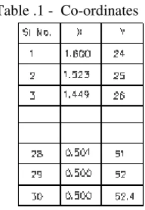
Flexible Diaphragm is a thin disc shaped part. The thin section has a varying thickness of 1 mm at the radius of 24mm to 0.5mm at the radius of 51.4mm. The section profile approximates to hyperbolic curve on one side and the other side is straight. This component is produced using Titanium alloy, Ti-6Al-4V. [2]
III.
GEOMETRY
As mentioned earlier, diaphragm is a thin part of varying section thickness. This part requires close dimensional, geometrical tolerances and surface finish requirements. The geometry of the diaphragm is as shown in fig.1.
Table .1 - Co-ordinates
Fig.1 - diaphragm
From fig.1, it may be observed that the diameters A and B are to be concentric within 0.03mm and surfaces P and Q are flat and parallel within 0.05mm and 0.005mm respectively. The surface finish of surfaces L and M are 0.1mm Ra to be finished by lapping. The required dimensional tolerances are also indicated in the component drawing.
IV.
FUNCTIONAL REQUIREMENT
OF DIAPHRAGM
Fig. 2 shows the PTO shaft assembly. PTO shaft has to absorb axial and angular misalignments. Axial
misalignments occur to the extent of ± 5 mm due to thermal variations and angular misalignments occur to the extent of 1.5° due to variations in EMAGB and AMAGB mountings in the aircraft. PTO SHAFT has number of design features; the shaft is designed to transmit a peak starting torque with constraint of weight less than 2 kg. The shaft is designed for static torque capacity of twice the peak torque. In the design, the safety feature is also considered by providing shear bolts to fail at the intended torque to safeguard the other precious components and sub assemblies.
Fig. 2 PTO shaft assembly
V.
MACHINING OF DIAPHRAGM
The diaphragm was machined using proper support, proper cutting tool and proper cutting parameters in a CNC lathe. During and after machining, the dimensional and geometrical parameters have to be measured. Different fixturing arrangement is for machining of diaphragms have been discussed in refereed paper [1], [2].
VI.
Measuring setup on CMM
The accuracy of scanning a component is dependent upon the measuring equipment or device used for measuring the component. For MAUSER three co-ordinates measuring machine model KMZ 201210 measuring uncertainty is given as:
(L/250000)+5 Microns in X-axis (L/250000)+3 Microns in Y-axis (L/250000)+4 Microns in Z-axis (L- Length measured in mm) [3], [4]
Fig.3 – CMM Measuring Setup
The readings were entered in the Excel formated work sheet. The thickness of the section will be automatically calculated and displayed in the work sheet as a report for documentation.
VII.
ANALYSIS OF MEASURING
METHOD ON CMM
The stylus in measuring instrument of CMM machine will exert a minimum of 0.1N force on the
measuring object as per typical CMM machine specification. From the results shown in table-2, the error due to deflection reading will be around 10microns. The initial conditions are (i) holding the diaphragm at a cord 20mm from the outer periphery. (Due to higher thickness the effective holding is at the periphery only). (ii) The load is applied at the 52.4 radius.
Table – 2, Deflection at different loads
Displacement scale 2000 : 1
It is observed that the present method of fixing the flexible plate on CMM is yields erroneous results, even though we use CMM for measurement
VIII.
PROBLEMS IN MEASURING
THIN SECTION ON CMM.
The section thickness at 104.8mm dia is 0.5mm.The diaphragm is made-up of two-phase titanium alloy. Due to the force applied by stylus to measure the dimensions, the following problems were identified
1. The diaphragm is deflecting and gives wrong mesurement.
2. Requires highly skilled personnel 3. Measuring on CMM is more costlier.
IX.
DEVELOPMENT OF MEASURING
SETUP
Considering the above points, a measuring setup was developed. It consists a base and a cover with holes located at different radial distances. The set up is shown in fig.4 & 5
Fig.4 Conceptual setup
Fig.5 – Measuring setup
The concept was modeled in Pro – E modeling software. The models are shown in fig. 6.
Fig .6, 3 D Model of the Setup
X.
ANALYSIS OF MEASURING
SETUP
Finite Element Model of the diaphram has been created with Quad 4 noded PLANE 42 element considering the Axisymmetry option.
The total number of elements and nodes in the section are
Static analysis has been performed to find out the deflection at the particular point for different load conditions.
Analyses were carried out under two different conditions of fixturing the diaphragms, namely, (i) diaphragms fixed at outer rim and (ii) diaphragms fixed in their bore
10.1 FLEXIBLE DIAPHRAGM-OUTER
Table-3, Deflection when diaphragm is fixed at outer rim
Displacement scale 8000: 1
10.2 FLEXIBLE DIAPHRAGM-INNER
Table-4, Deflection when diaphragm is fixed in its bore.
Displacement scale 100000: 1
Table – 5, Deflection when diaphragm is fixed at outer rim.
Displacement scale 8000: 1
Table – 6, Deflection when diaphragm is fixed in its bore
Displacement scale 100000: 1
XI.
RESULTS AND DISCUSSIONS
From the table 3,4,5 & 6 the maximum deflection is about 13.7 micron for 3N force. So the maximum possible error is 13.7 microns when 3N force is exerted by pin in table 5.
error amount will always be less than 2 micron. It is highlighted in green color in table 5.
Table – 7 comparison of results from CMM and new measuring setup
FLAT SIDE PROFILE SIDE
CUMUL ATIVE DIFF. Y CMM MANU
AL
DIFF=C MM-MAN
CMM MANU AL
DIFF=C MM-MAN
26 2.992 2.993 -0.001 0.150 0.146 0.004 0.003 27 2.994 2.990 0.004 0.218 0.223 -0.005 -0.001 28 2.992 2.980 0.012 0.287 0.299 -0.012 0.000
-- -- -- --- -- -- -- -
-- -- -- --- -- -- -- -
48 3.016 2.984 0.032 1.044 1.067 -0.023 0.009 49 3.014 2.989 0.025 1.058 1.081 -0.023 0.002 50 3.013 2.988 0.025 1.067 1.098 -0.031 -0.006 51 3.010 2.968 0.042 1.076 1.112 -0.036 0.006
Table – 7 shows the comparative diferences between the readings of CMM and the measuring setup. The diferences are only in few microns. It is further anlysed and observed that the differences are due to stylus force.
XII.
CONCLUSION
A simple measuring setup for thin section felxible diaphragms has been developed. The newly developed measuring method without CMM and the existing measuring method on CMM were analyzed using ANSYS software,
The measurements taken using CMM and newly developed setup have been compared. The results of new development are found satisfactory.
The existing method of measurement using CMM was bound to be error prone and alternate measuring fixtures have been suggested.
The proposed measuring method without CMM is observed to be most realiable. It does not involve costly machine hour and man hour. The measuring fixture is very simple and fool proof. Thus any industry with or without CMM can be involved in the machining (and development) of flexible diaphragms.
REFERENCE
[1.] C.Chandrasekaran and A.Velayudham,
“Development of Hydraulic backup for thin Titanium parts”, RAMP 2001, Annamalai
University, Chidambaram 7- 8 Sep 2001. [2.] C.Chandrasekaran & A.Velayudham,
“Qualitative Approach for Machining Thin
Section Titanium Components”, 19th AIMTDR 2000, IIT- Madras, 14-16 Dec 2000
[3.] C. Chandrasekaran and A.Manoharan,
“Auto Scanning and Machining a 3D –
Surface” National Seminar on Computer Integrated Manufacturing, Anna University, Madras 600 025, 23 – 24 march – 1995 [4.] User Manual, Mauser three Coordinate