C.Srinivasan. Int. Journal of Engineering Research and Application www.ijera.com
ISSN : 2248-9622, Vol. 6, Issue 11, ( Part -5) November 2016, pp.09-12
www.ijera.com 9 | P a g e
Design and Implementation of HDMI Transmitter
1
C.Srinivasan,
2K.ArulOli
1,2Asst. Professor, Department of EEE, Kingston Engineering College, Vellore
ABSTRACT
The High-Definition Multimedia Interface is provided for transmitting digital television audio-visual signals from DVD players, set-top boxes and other audio-visual sources to television sets, projectors and other video displays. HDMI is used in various real time applications for transmitting and receiving audio-visual Signals. A transaction level model of HDMI Transmitter is designed by using System Verilog. Transaction Level Modeling methodologies promote the growth of System Level Description Language. This paper presents a HDMI Transmitter Transaction Level Modeling Design which can be used to easily transform to HDL descriptions for subsequent RTL (Register Transfer Level) Design.
Keywords: HDMI, System Verilog, RTL, HDL, Transaction Level Modelling
I.
INTRODUCTION
High-Definition Multimedia Interface [1] can carry high quality multi-channel audio data and can carry all standard and high definition consumer electronics video formats. HDMI can also carry control and status information in both directions.
System Verilog has been the industry's first unified Hardware Description and Verification Language. It has became an official IEEE Standard
1800™ in 2003 under the development of
Accellera [3].. It can be built with or without timing delay as a programmer’s view, or be built as an accurate cycle Model [7]. System Verilog is widely used to specify, design and implement complex system.
II.
HIGH-DEFINITION MULTIMEDIA
INTERFACE
HDMI System Architecture is defined to consist of Sources and Sinks. A given device may have one or more HDMI inputs and one or more HDMI outputs. Each HDMI input on these devices shall follow all of the rules for an HDMI Sink and each HDMI output shall follow all of the rules for an HDMI Source.
HDMI transmitter is a component that is responsible for driving the four differential TMDS channels output pairs into an HDMI output and for clocking the data driven into those four output pairs.
The features of HDMI 2.0 are listed below,
Enables transmission of High Dynamic Range (HDR) video
Bandwidth up to 18Gbps
4K@30/60 (2160p), which is 4 times the clarity of 1080p/60 video resolution
Up to 32 audio channels for a multi-dimensional immersive audio experience
Up to 1336kHz audio sample frequency for the highest audio fidelity
Simultaneous delivery of dual video streams to multiple users on the same screen
Simultaneous delivery of multi-stream audio to multiple users (Up to 4)
Support for the wide angle theatrical 21:9 video aspect ratio
Dynamic synchronization of video and audio streams
CEC extensions provide more expanded command and control of consumer electronics devices through a single control point
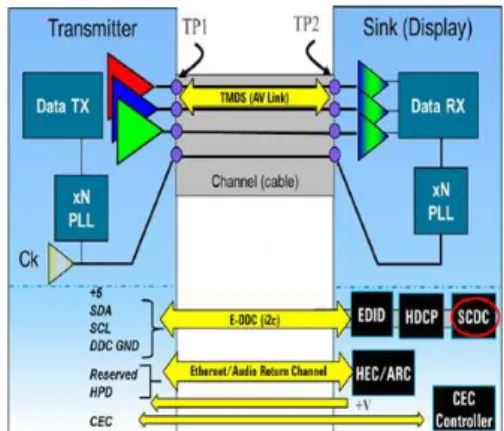
Figure 1 HDMI 2.0 Block Diagram
As shown in Figure 1, the HDMI cable and connectors carry four differential pairs that make up the TMDS data and clock channels. These channels are used to carry video, audio and auxiliary data. In addition, HDMI carries a VESA DDC channel. The DDC is used for configuration and status exchange between a single Source and a
C.Srinivasan. Int. Journal of Engineering Research and Application www.ijera.com
ISSN : 2248-9622, Vol. 6, Issue 11, ( Part -5) November 2016, pp.09-12
www.ijera.com 10 | P a g e single Sink. The optional CEC protocol provides
high-level control functions between all of the various audiovisual products in a user’s environment
2.1 Brief Description of the HDMI
In HDMI system, all Video data can have a pixel size of 24, 30, 36 or 48 bits, and which that at the default 24-bit color depth is carried at a TMDS clock rate equal to the pixel clock rate. To keep the balance of system rule, those higher color depths are carried using a correspondingly higher TMDS clock rate. Video formats with TMDS rates below 23MHz can be transmitted using a pixel-repetition scheme. The video pixels can be encoded in either RGB, YCBCR 4:4:4 or YCBCR 4:2:2 color space[8]. As we know, Basic audio contains a single format IEC 60938 L-PCM audio stream at sample rates of 32kHz, 44.1kHz or 48kHz. HDMI can optionally carry such audio at sample rates up to 192KHz and also has 3 to 8 audio channels, and support to carry an IEC 61937 compressed (e.g. surround-sound) audio stream at bit rates up to 24.376Mbps. HDMI can also carry from 2 to 8 channels of One Bit Audio and a compressed form of One Bit Audio called DST.
2.2 Packing and Encoding
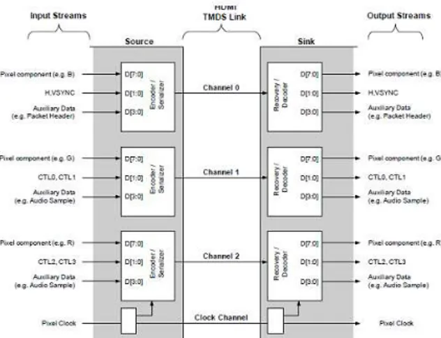
An HDMI physical link includes three TMDS Data channels and a single TMDS Clock channel as shown in Figure 2. The TMDS Clock channel constantly runs at a rate proportional as the pixel rate of the transmitted video. Each of the three TMDS data channels transmits a 10-bit character during every cycle of the TMDS Clock channel. This 10-bit word is encoded using one of several different coding techniques.
Figure 2 HDMI Encoder/Decoder Overview
As described at Figure 2, the input data stream to the Source’s encoding logic module will contain video pixel (e.g. B), packet (e.g. Audio
Sample) and control data. The source transmitter encodes 2 bits of control data, 4 bits of packet data or 8 bits of video data per TMDS channel to 10 bits output, and the Source encodes one of these data types or encodes a Guard Band character on any given clock cycle.
As for transmission audio and auxiliary data across three TMDS channels, HDMI uses a packet structure. For the purpose of the higher reliability required of audio and control data, this data is used with a BCH error correction code and is encoded with a special error reduction coding method to produce the 10-bit output word that is transmitted on the TMDS channels.
III.
SYSTEM VERILOG FEATURE
System Verilog provide some key elements for hardware and system-level modeling or UVM style verification. Object-Oriented Programming (OOP) lets you create complex data types and tie them together with the routines that work with them. You can create test benches and system-level models at a more abstract level by calling routines to perform an action rather than toggling bits. When you work with transactions instead of signal transitions, you are more productive.Transaction Level Model (TLM) is a term used to identify a reference model that implements the required functionality at a very high level of abstraction [3]. Given the RTL code is written at a low level of abstraction, TLM's are usually written more quickly and efficiently capture the expected function of the device. System Verilog support to use a Extensible verification method library such as UVM and VMM for verification and modeling.
IV.
FUNCTIONAL TRANSMITTER
MODEL
This part presents a functional level model of HDMI Transmitter. The model is divided into separate sections according to different functions, and the module includes various user-definable switches. We built the whole model by the method of OPP and TLM, so it either has a feature of clearly and easily maintained structure, or correspond the mainstream standard modeling methods.
4.1 The Overall Design
C.Srinivasan. Int. Journal of Engineering Research and Application www.ijera.com
ISSN : 2248-9622, Vol. 6, Issue 11, ( Part -5) November 2016, pp.09-12
www.ijera.com 11 | P a g e interface such as a driver and a monitor as a class.
Sequencer is as sequence generator, controlling that which of the transaction should be sent to the driver depending on the needs of driver. Driver is the Bus Function Model (BFM), whose function is to abstract data from the upper streams into the signal level and sent them to the interface.
Transaction level is the core of TLM transport. The flow of data across internal model is based on packet units.. Thus the core of the transmitter is the class of transaction and its member functions, which is used to capture the data and drive it out according to the protocol. The config part is also a config type class which contains all the parameters that need to set for the model.
4.2 The Data Encoding Design
The encoding module put into the interface, and encoding process is designed full accordance with protocol requirements. The upstream module drives the transaction into interface, and spilt into three-way 8 bit RGB, 4bit auxiliary data or 2bit control data in different time.
Video Data Periods use the way of Transition Minimized Differential encoding to transfer eight bits data in each channel, a total of 24, showing a video pixels. Data Island Periods using a similar method with minimized differential coding, is called TMDS Error Reduction Coding (TERC4), each channel transmitting four data per clock cycle, a total of two data transfer. Control Periods, transfer two data per channel, a total of six bits data which are HSYNC, VSYNC, CTL0, CTL1, CTL2 and CTL3. So, in each TMDS clock cycle, use Transition Maximized encoding for those 2bits data.
4.3 The Data Generating and Scheduling Design HDMI transmitter is designed mainly lies in the capture of upstream video and audio data and packing by the protocol. The modeling process is using TLM model which a transaction is a transmission unit. So a frame image is a transaction, and all the data which needs to transmit must put in this transaction.
Firstly, transaction was defined as a class, which has three member functions, respectively using for generating video data, generating data island and group packages output. These three functions are all nested different classes and functions. Video generation module generates HSYNC, VSYNC, DE and other signal which are used to constitute a frame image. When DE signal is valid, that is, HSYNC and VSYNC invalid video period, then the three channels transmit video data. When DE signal is invalid, that is, HSYNC and VSYNC valid for
the data island period, then transmit the auxiliary data which is generated by data island packet module, and it contains audio sample package and other supplementary information package. In the middle of the data island period and the video period must have a control period, and HSYNC and VSYNC signal are transmitted outward through the control period. The entire process of data scheduling is done by a function of packing data out.
V.
SYSTEM MODEL VERIFICATION
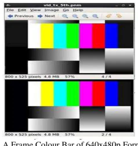
The way to verify the HDMI transmitter model was using a proven HDMI receiver's IP, and comparing the video and audio data whether can complete transmission by connecting and some related configuration. Video transmission use the color bar, and it allows you to quickly check the source, transmission, sink, signal black and white level display prospective, especially mainly use to confirm the entire signal flow in the color encoding and decoding is whether normal or not. In this test case, we choose the video format of 640x480p.As show in Figure 3(a), we firstly use the waveform of channel 0 outputs to show that three channels corresponding to the time sequence as their rule. In addition, comparison of channel 0 video data of transmitter and receiver pre-encoded data indicate the correctness of video data transmits as Figure 3(b). Finally, we show a comparison of the frame picture of color bar as Figure 3(c).
(a) Waveform of Transmitter Output before Encoding
C.Srinivasan. Int. Journal of Engineering Research and Application www.ijera.com
ISSN : 2248-9622, Vol. 6, Issue 11, ( Part -5) November 2016, pp.09-12
www.ijera.com 12 | P a g e c) A Frame Colour Bar of 640x480p Format
Figure 3 HDMI Transmitter Model Video Verification
In the audio transmission verification section, we stored a sampling rate of 32 KHz audio data in a file, and read from transmitter model. The model grouped the audio data in accordance with IEC60938 package type and then grouped frame by protocol of HDMI, in conjunction with various auxiliary information packet transmission, such as audio Clock Regeneration packet and General Control packet, which is used to restore the audio clock or control the audio mute and so on. As Figure 3(a), it shows that audio sample data transmit at the data island period and audio frequency is regenerated by receiver. According to the equation of 128*fs at two end, we used a period of signal AUD_NFS to calculate the regenerated frequency was 32 KHz. In order to verify the correctness of transmission, we stored the audio data in two files for comparison, as specified in Figure 3 (b):
(a) Waveform of video data
(b) Waveform of Audio Data Figure 4 HDMI Transmitter Model Audio
Verification
VI.
CONCLUSION
In this paper, it completes a model in HDMI transmitter by high-level object-oriented modeling approach. This article in-depth studies the new features in System Verilog language for modeling, and analyzes the principles and algorithms of HDMI Audio and Video Transmission. It accomplishes a non-timing reusable transaction level model which is not only supported 32 video format types and 7 audio types but also 300% faster than RTL model.
REFERENCES
[1]. www.hdmi.org “HDMI Specification 1.3a”
[2]. Jiang Xiong, Qing Ming Yi and Min Shi, Applied Mechanics and Materials, p.4094-4097(2013).
[3]. Martin Keaveneyt, Anthony McMahont, ISSC 2008, Galway, June 18-19, p.323-330 (2008).
[4]. Lingling Chai, Zheng Xie and Xin’an
Wang, 2014 IEEE International Conference on Electron Devices and Solid-State Circuits, p.389(2014).
[5]. Sang-Bong Byun, Young-Hyung Kim, International Journal of Control and Automation, p.191-200(2013).
[6]. Jian Wang, Hong Wang, and Zhijia Yang, ASICON 2009 Proceedings, 2009 8th IEEE International Conference on ASIC, p.97-100(2009).
[7]. Gao Yingke, Wu Diancheng and Li Quanquan, 2013 IEEE 10th International Conference on ASIC, ASICON 2013(2013).