ISSN 1546-9239
© 2005 Science Publicatio
Corresponding Author: Slim Ben Saoud, L.E.C.A.P.-E.P.T./ I.N.S.A.T. - B.P. 676, 1080 Tunis Cedex, Tunisia 1331
Codesign Methodology of Real-time
Embedded Controllers for Electromechanical Systems
1
Slim Ben Saoud,
2Andreas Gerstlauer and
2Daniel D. Gajski
1L.E.C.A.P.-E.P.T./ I.N.S.A.T.-B.P. 676, 1080 Tunis Cedex, Tunisia
2CECS - UCI - Irvine, CA 92697-3425, USA
Abstract: Under increasing time-to-market pressures in the electric drives industries, the development time of new algorithms and new control systems including their debugging time must be minimized. This requirement can be satisfied only by using a well-defined system-level design methodology and by reducing the migration time between the algorithm development language and the hardware specification language. In this study, we propose to apply the SpecC methodology to the design of control systems for power electronics and electric drives. We first begin with an executable specification model of the control device. Then, we describe the different steps and transformations used to convert this model to a communication model and finally into an implementation model ready for manufacturing.
Key words: Co-design methodology, embedded systems, digital control, electric process
INTRODUCTION
Nowadays, motor control is being a vast market and the motor control industry is being a strong aggressive sector. To remain competitive, the industry has to develop sophisticated control systems which are often composed of standard processors (µP, µC, DSP)[1,2] and specific hardware components (ASSP, FPGA, ASIC)[3-6]. Design of these systems represents a difficult and studious task. Traditionally, engineers work on implementation of new control algorithms directly on an existing control device. Such projects typically require 6 to 12 man-months and are composed mainly of: (i) implementation of the developed algorithm on the processor (after coding); (ii) configuration and programming of the processor peripherals for I/O operations; (iii) development, if needed, of other interface circuits; (iv) test and debugging of the obtained control system (usually by using emulators); and finally, (v) validation of the system by experimentation. All these tasks needed in order to adapt the new algorithm to a given control board are usually done manually. As a result, neither the system performance nor the design time is significantly optimized.
A new trend is to use configurable logic circuits (FPGA, CPLD, etc.) with processor units on the same board. The use of these circuits allows rapid and efficient adaptation of the used board to new applications. However, partitioning between these processing elements is still done in an ad - hoc way. Therefore, important delays can be introduced into the design process, mainly if the first decision about partitioning of the application is not correct.
To summarize, the design of the control systems remains a delicate task, which is usually done manually
and the design decisions are made heuristically. Consequently, resulting products are usually not optimal and the time-to-market is relatively large.
To resolve these problems, we suggest to apply the SpecC methodology[7,8] to the design of embedded control systems. This methodology presents two main advantages: (i) productivity gains by using automatic refinement tools and (ii) faster design space exploration by using intermediate models that are at higher levels of abstraction and provide rapid and useful feedback.
The benefits of the SpecC methodology have previously been demonstrated on several industrial-strength data-dominated, multimedia examples[8]. In this study, we present the successful use of this methodology for control-dominated system design. This approach will be discussed using an application of the direct-current (DC) motor control. A generalization of this study to any other control system can be done easily using the same steps discussed below.
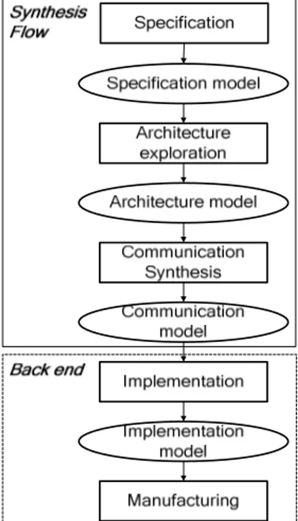
Fig. 1: SpecC methodology
Fig. 2: General diagram defining the control algorithm ( ref: the speed reference; Iref: the current reference; α: the pulse width of the control
signal; Vh: the voltage applied to the motor; Im: the motor current and m: the motor speed)
The specification model describes the functionality as well as performance, power, cost and other constraints of the intended design. It is a purely functional description and does not include any premature allusions to implementation details.
During architecture exploration the specification model is refined into an architecture model. This includes the following design steps: (i) allocation which determines the number and types of system components such as general-purpose or custom processors, memories and busses, which will be used to implement the system behavior; (ii) behavior partitioning which maps the behaviors (or processes) that comprise the system functionality onto the allocated processing elements; (iii) variable partitioning which assigns variables to memories; (iv) channel partitioning which assigns communication channels to busses; and (v) scheduling which determines the order of execution of the behaviors assigned to either the standard (software) or custom (hardware) processors after partitioning.
Architecture exploration is an iterative process culminating in an architecture model that represents a refinement of the specification model. Each candidate architecture is estimated to evaluate satisfaction of the design constraints. If constraints are not met, component reallocation is performed and a new architecture with different components, connectivity, partitioning, or scheduling is generated and evaluated.
The architecture model describes the system functionality as well as the overall structure of the final implementation for the design. Communication in the architecture model is described using abstract global channels on the message-passing level.
Communication Synthesis refines the abstract communication between components in the architecture model into an implementation over actual busses. The task of communication synthesis includes insertion of communication protocols, synthesis of interfaces and transducers and inlining of protocols into synthesizable components. In the resulting communication model, communication is described in terms of actual wires and timing relationships defined by the bus protocols.
The communication model is the final output of the system-level design process which describes the system structure as a set of components connected through pins and wires of the set of system busses.
In the backend, the result of the synthesis flow is handed off to the backend tools, as shown in the lower part of Fig. 1. For the software part, compilers are used to translate the software C code for the chosen processor. For the hardware part, high-level synthesis tools implement the behavioral C code describing the functionality assigned to custom hardware and the functionality of transducers which are necessary for connecting different processors, memories and IPs. After software compilation and hardware synthesis, the final implementation model is generated.
The implementation model represents a clock-cycle accurate description of the whole system. This description, in turn, then serves as the basis for manufacturing of the system using traditional tools for logic synthesis and physical design.
EMBEDDED CONTROLLER DESIGN
Description of the case study: The studied process is composed of a Direct Current (DC) motor, a four-quadrant chopper, a current sensor (LEM) for the current capture and an optical incremental encoder (OIE) for the speed capture.
The used control algorithm is composed of two control loops: an outer motion control loop with a functioning period Tm and an inner current control loop with a functioning period Tc (Fig. 2).
The speed regulator computes the current reference value Iref from the speed reference ref introduced by the user and from the motor speed value m. The current regulator computes the pulse width α of the
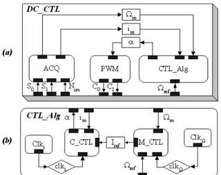
1333 Fig. 3: Specification model: overview of the DC_CTL
behaviors
Fig. 4: Architecture models after behavior partitioning
Fig. 5: Communication model after protocol in lining
The interconnection of the components implementing these regulators to the physical process (chopper, motor and sensors) is done by using Input/output (I/O) interfaces. For the studied DC process, we use a Pulse Width Modulation module (PWM) to generate two complementary control signals from the α value. These signals are applied to the
control of the chopper functioning and therefore the motor speed. The current and speed digital values (Im and m) are obtained from the sensor output signals by using capture modules (ACQi and ACQ ) which translate information from the logic and analog domain to the digital one.
Specification: The specification model of the studied system is composed of three modules encapsulated in SpecC behaviors (Fig. 3a): (i) CTL_Alg for the control algorithm, (ii) ACQ for the information acquisition and (iii) PWM for the generation of control signals. Each of them can be split up into different sub-behaviors associated with different clocks. As an example, Fig. 3b shows the control algorithm split up into two sub-behaviors: M_CTL which represents the speed regulator and C_CTL which represents the current regulator.
The SpecC specification describes the control device functionality in a clear and precise way as it uses a modular and hierarchical representation. The resulting model is executable and allows the validation of the developed algorithm by simulation. Using the SpecC specification, we were able to evaluate several different variants of the control algorithm in a matter of hours.
Architecture exploration: For the design of control devices, the I/O modules are usually implemented as hardware modules (ADC, Timers, etc.) while the control algorithm is implemented in a standard processor. However, this solution is not always adequate for real time requirements of sophisticated algorithms. In these cases, we have to move the critical tasks (such as the current regulator) of the control algorithm from the processor into custom hardware.
According to these considerations, we explored several architecture solutions for the implementation of the algorithm ranging from a pure software solution to a pure hardware one. However, as a compromise between real-time performance, flexibility and user-friendliness, we only considered mixed solutions which include HW and SW components. Specifically, Fig. 4 shows the two possible candidate architecture models we developed for the DC-process controller.
At this stage of architecture exploration, SpecC tools allow estimation of certain quality metrics such as performance, power consumption, etc. Results showed that the execution time of C_CTL is reduced by 88% (from 5 µs down to 0.6 µs) when moving C_CTL from software to hardware. Furthermore, C_CTL takes up 70% of the DSP utilization (compared to 2 µ s execution time of M_CTL), i.e. moving C_CTL into hardware frees up the processor for other tasks and/or for power savings. We therefore selected the second architecture model (Fig. 4b) which is composed of: (i) a hardware component (PE1-ASIC) implementing the I/O modules and the current control module; and (ii) a processor core (DSP56600 core) for both of the speed control module and the interface with the user (PE2-DSP).
Fig. 6: RTL processor implementing the C_CTL module
Fig. 7: RTL processor implementing the EXCH module
Fig. 8: Co-simulation results of the C_CTL hardware module
At the beginning of each new Tc period, the ASIC interrupts the DSP and both start the exchange process. Acquisition of Ωm values is done by the master at the beginning of each Tm period.
Communication synthesis: We used the DSP 56600 bus protocol[9] for both the ASIC and the DSP. The
communication model is generated using two steps: protocol insertion (protocol of the DSP 56600) and protocol inlining into the ASIC.
The resulting communication model is shown on Fig. 5. Note that we added a hardware exchange module (EXCH) to the C_CTL module for implementation of its communication with the DSP.
IMPLEMENTATION AND VALIDATION
1335 Fig. 9: Implementation characteristics of different
hardware modules
Validation of the implemented hardware modules:
The implemented hardware modules have been validated separately by co-simulation using Xilinx System Generator and Matlab tools. Results are compared to those of a software floating-point implementation. Figure 8 shows the obtained relative errors on the current and speed values and demonstrates the efficiency of the designed system.
The different hardware modules have been implemented using Xilinx Virtex2XC2V250 type FPGAs. The resulting design characteristics are summarized in Fig. 9.
These results show that the designed hardware modules occupy less than 30% of the circuit surface. We can therefore confirm that hardware implementation of digital control devices is nowadays very advantageous given the high integration scales of FPGA circuits and the performance of EDA tools.
DISCUSSION
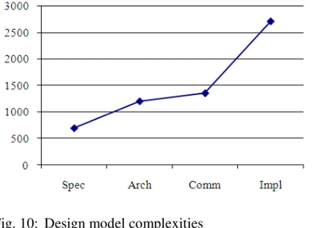
Figure 10 and Table 1 show the results for the design of the controller system from specification model down to implementation model.
To validate the models, we performed simulations at all levels. As we move down in the level of abstraction, more timing information is added, increasing the accuracy of the simulation results.
As the results show, moving to higher levels of abstraction enables more rapid design space exploration. Through the intermediate models, valuable feedback about critical design aspects can be obtained early and quickly.
As code sizes for different models suggest, more lines of code are added to the model with lower levels of abstraction, reflecting the additional complexity needed to model the implementation details introduced with each step. Table 1 demonstrates with the use of available refinement tools that can automatically generate all design models from the initial specification model, large productivity gains of 500x or more can be achieved (especially for the sophisticated control systems).
Fig. 10: Design model complexities
Table 1: Refinement effort
Modified Manual Automated lines User/Refine Spec → Arch 550 1~2 weeks 5mins / <0.5min Arch → Comm 200 0.5~1week 5mins / < 0.5min Comm → Impl 2000 4~8 weeks 40mins / <4mins Total 2750 5.5~11 weeks 50mins / <5mins
The implementation results of the DC process controller demonstrate the importance and efficiency of VLSI technology in the development of real-time, control-dominated systems. Using the SpecC methodology and associated EDA tools, the presented design was implemented as a circuit on a single FPGA component and completed in a matter of weeks.
Moreover, with the evolution of semiconductor technology and the development of efficient CAD tools, the use of the FPGA circuits will become increasingly important, particularly for developing reconfigurable SOC (RSOC) specific to process control. These RSOC involve the integration of different PEs (such as processors and peripherals) and their interconnection on the same reconfigurable component[10,11].
The use of co-design methodologies and RSOC techniques and tools[12,13] will be very advantageous for rapid and efficient development of digital control devices. In future work, we are planning to develop IPs specific to the automation domain. Furthermore, we are studying the efficient integration of such IPs into RSOC systems and system design methodologies.
CONCLUSION
We have shown the various steps that gradually refine the initial specification down to a detailed communication model. This model is then further implemented using traditional CAD tools and FPGA circuits.
Using the SpecC methodology, we were able to finish the complete design in a short amount of time. Results show that with the help of automatic refinement tools, significant productivity gains can be achieved. Furthermore, intermediate models at every stage of the design process provide useful feedback about design quality metrics for rapid, early design space exploration, allowing us to evaluate several algorithm variants and candidate architectures. In summary, the well-defined nature of the methodology’s models and transformations helps focusing design efforts on central issues, provides the basis for design automation tools and enables application of formal methods in the future.
ACKNOWLEDGMENTS
The authors would like to thank the Fulbright Scholar Program for supporting this project. We would also like to thank Prof. Rainer Dömer for his interesting comments and his support.
REFERENCES
1. Zhang, W., G. Feng, Y.F. Liu and B. Wu, 2004. A digital Power Factor Correction (PFC) control strategy optimized for DSP. IEEE Trans. Power Electronics, 19: 1474-1485.
2. He, D. and R.M. Nelms, 2004. Fuzzy logic average current-mode control for DC/DC converters using an inexpensive 8-bit microcontroller. The IEEE Industry Applications Conf., 4: 2615-2622.
3. Peyravi, H., A. Khoei and K. Hadidi, 2002. Design of an analog CMOS fuzzy logic controller chip. Fuzzy Sets and Systems, 132: 245-260.
4. Takahashi, T. and J. Goetz, 2004. Implementation of complete AC servo control in a low cost FPGA and subsequent ASSP conversion. 19th Ann. IEEE Applied Power Electronics Conf. and Exposition 1: 565-570.
5. Abu-Rub, H., J. Guzinski, Z. Krzeminski and H.A. Toliyat, 2004. Advanced control of induction motor based on load angle estimation. IEEE Trans. Industrial Electronics, 51: 5-14.
6. Oh, S.N., K.I. Kim and S. Lim, 2003. Motion control of biped robots using a single-chip drive. IEEE Intl. Conf. Robotics and Automation 2: 2461-2465.
7. Gajski, D., J. Zhu, R. Dömer, A. Gerstlauer and S. Zhao, 2000. SpecC: Specification Language and Methodology. Kluwer Academic Publishers. 8. Gerstlauer, A., R. Dömer, J. Peng and D. Gajski,
2001. System Design: A Practical Guide with SpecC. Kluwer Academic Publishers.
9. Motorola, Inc., Semiconductor Products Sector, DSP Division, 1996. DSP 56600 16-bit Digital Signal Processor Family Manual, DSP56600FM/AD.
10. Banerjee, S. and N. Dutt, 2004. Efficient search space exploration for HW-SW partitioning. CODES + ISSS’04, pp: 122-127.
11. Lee, T.L. and N.W. Bergmann, 2004. Interfacing methodologies for IP re-use in reconfigurable system-on-chip. Proc. of SPIE -Microelectronics: Design, Technology and Packaging, 5274: 454-463.
12. Lysecky, R., F. Vahid and S.X.D. Tan, 2004. Dynamic FPGA routing for just-in-time FPGA compilation. Proc. 41st Ann. Conf. Design Automation, pp: 954-959.