ORIENTAÇÃO
David Sardinha Andrade de Aveiro
Duarte Nuno Freitas Pinto
MASTER IN INFORMATICS ENGINEERINGAnalysis an Development of a Prototype Based on
Media Wiki and Semantic Media Wiki Integrated with
a Design Modeling that Allows Modeling of
i
Abstract
In a world where organizations are ever more complex the need for the knowledge of the organizational self is a growing necessity.
The DEMO methodology sets a goal in achieving the specification of the organizational self capturing the essence of the organization in way independent of its implementation and also coherent, consistent, complete, modular and objective.
But having such organization self notion is of little meaning if this notion is not shared by the organization actors. To achieve this goal in a society that has grown attached to technology and where time is of utmost importance, using a tool such as a semantic Wikipedia may be the perfect way of making the information accessible.
However, to establish DEMO methodology in such platform there is a need to create bridges between its modeling components and semantic Wikipedia.
It’s in that aspect that our thesis focuses, trying to establish and implement, using a
study case, the principles of a way of transforming the DEMO methodology diagrams in comprehensive pages on semantic Wikipedia but keeping them as abstract as possible to allow expansibility and generalization to all diagrams without losing any valuable information so that, if that is the wish, those diagrams may be recreated from the semantic pages and make this process a full cycle.
ii
Resumo
Num mundo em que as organizações são cada vez mais complexas a existência do
conhecimento do “ser” organizacional é uma necessidade crescente.
A metodologia DEMO propõe-se a conseguir esta especificação do “ser” organizacional
capturando a essência da organização de forma independente da sua implementação e de maneira coerente, consistente, completa, modular e objetiva.
Mas de pouco serve deter a noção sobre o “ser” organizacional se esta não for partilhada
pelos seus intervenientes. Para este fim, numa sociedade cada vez mais ligada à tecnologia em que o tempo é um bem essencial, a utilização de uma ferramenta como um Wikipedia Semântico pode ser o modo perfeito de divulgação.
Mas para conseguirmos estabelecer a metodologia DEMO em tal plataforma, é necessário estabelecer pontes entres os seus componentes e o Wikipedia Semântico.
É nesse aspeto que a nossa tese se foca, tentando estabelecer e implementar em um caso de estudo os princípios de uma forma de transformar os diagramas da metodologia DEMO em páginas compreensíveis no Wikipedia Semântico mas de forma o mais abstrata possível para permitir expansibilidade e generalização a todos os diagramas e, sem perdas de informação, para que, se tal for o desejo esses diagramas possam ser recriados a partir das páginas semânticas e assim tornar o processo num ciclo completo.
iii
Index
INDEX ... III
IMAGE INDEX ... V
TABLE INDEX ... VII
1. INTRODUCTION ... 1
1.1. MOTIVATION... 1
1.2. OBJECTIVES ... 1
1.3. ORGANIZATION ... 2
2. STATE OF ART ... 4
2.1. BASIC NOTIONS ... 4
2.1.1. ENTERPRISE ONTOLOGY... 4
2.1.2. MODEL TRIANGLE ... 4
2.1.3. ONTOLOGY OF A WORLD... 7
2.1.4. WORLD ONTOLOGY SPECIFICATION LANGUAGE ... 9
2.1.4.1. WOSL GRAMMAR ... 10
2.1.5. DESIGN AND ENGINEERING METHODOLOGY FOR ORGANIZATIONS ... 11
2.1.6. DEMOMETA MODEL ... 18
2.1.7. MEDIA WIKI ... 21
2.1.8. SEMANTIC MEDIAWIKI ... 21
2.2. DESIGN TOOLS STATE OF THE ART ANALYSIS ... 22
2.2.1. XEMOD ... 22
2.2.2. VISIO ... 23
2.2.3. DIA ... 23
2.2.4. KIVIO ... 23
2.2.5. OTHERS ... 24
3. IMPLEMENTATION ... 26
3.1. EXAMPLE CASE USED ... 26
3.2. VALIDATION RULES FOR DIAGRAMS ... 27
3.3. CHANGES IN THE DEMOMETA MODEL ... 27
3.4. XML IMPLEMENTATION OF ATD AND OFD DIAGRAMS ... 30
3.5. STENCILS IMPLEMENTATION ... 30
3.6. XEMOD IMPLEMENTATION ... 30
3.7. DIAIMPLEMENTATION ... 31
3.8. KIVIO IMPLEMENTATION... 34
3.8.1. KIVIO PHP PARSER ... 36
3.8.2. KIVIO PROBLEMS ... 36
iv
3.9.1. PSDSTENCIL ... 38
3.9.2. UNIVERSAL VISIO META MODEL FOR DEMO ... 39
3.9.1. CONCRETE IMPLEMENTATION OF UVMMD ON A DIAGRAM ... 46
3.9.2. VISIO VBA SOLUTION ... 49
3.9.3. VISIO PHP PARSER ... 54
3.10. SEMANTIC MEDIA WIKI IMPLEMENTATION ... 56
3.11. PHPPARSER OUTPUT ... 60
3.12. AEXPANDABLE SOLUTION ... 62
3.12.1. FORMATTING IN VBA ... 62
3.12.2. PHP PARSER WITH XML RULES AND PARAMETERS ... 65
4. FUTURE DEVELOPMENT ... 69
4.1. CREATION OF VALIDATION RULES IN VISIO ... 69
4.2. GENERALIZATION OF THE VBA SOLUTION ... 69
4.3. COMPLETING THE CYCLE ... 70
5. CONCLUSION ... 71
BIBLIOGRAPHY ... 72
APPENDIX ... 74
A.1 LIBRARY CASE ... 74
A.2 PHPCODE KIVIO PARSER ... 76
A.3 SMWINSTALLATION GUIDE ... 78
A.4 XMLPATTERN FOR SEMANTIC MEDIAWIKI EXPORTATION ... 82
A.5 XMLPROPERTY LIST FOR EACH SHAPE... 87
v
Image
Index
Image 1: Model Triangle [1] ... 6
Image 2: Statum Type Declarations [1] ... 10
Image 3: Reference Law [1] ... 10
Image 4: Dependency Law [1] ... 10
Image 5: Unicity Law [1] ... 11
Image 6: Basic Transaction Pattern [1] ... 12
Image 7: Enclosed Transaction [3] ... 12
Image 8: Self Activating Transaction [3] ... 13
Image 9: Costumer Transaction [3] ... 13
Image 10: Distinction Axiom Summary [1] ... 14
Image 11: Organization Theorem Representation [1] ... 14
Image 12: Aspects Model [1] ... 15
Image 13: ATD Basic Elements [3] ... 16
Image 14: ATD Basic Constructs [3] ... 16
Image 15: PSD basic elements [3] ... 17
Image 17: Meta State Model [7] ... 19
Image 18: Meta Construction Model [7] ... 20
Image 19: Meta Process Model [7] ... 20
Image 20: Meta Action Model... 20
Image 21: Library ATD Diagram (Visio)... 26
Image 22: Library OFD Diagram (Visio) ... 27
Image 23: Proposition for the DEMO Meta Construction Model ... 28
Image 24: Proposition for the DEMO Meta State Model ... 29
Image 25: DEMO Meta Process Model ... 30
Image 26: DEMO Meta Action Model ... 30
Image 27: Access database of Library exported from Xemod ... 31
Image 28: DIA Stencil Creation ... 32
Image 29: DIA Implementation of Library ATD ... 33
Image 30: Importation of Library ATD in DIA with no stencil set ... 33
Image 31: Kivio Stencils ... 35
Image 32: Library representation in Kivio ... 36
Image 33: New PSD stencil - shapes list ... 38
Image 34: Universal Visio Meta Model for DEMO ... 39
Image 35: Universal Visio Meta Model for DEMO – Part 1 ... 40
Image 36: Universal Visio Meta Model for DEMO – Part 2 ... 41
Image 37: Universal Visio Meta Model for DEMO – Part 3 ... 42
Image 38: Universal Visio Meta Model for DEMO – Part 4 ... 44
Image 39: Universal Visio Meta Model for DEMO – Part 5 ... 44
Image 40: Universal Visio Meta Model for DEMO – Part 6 ... 45
Image 41: Universal Visio Meta Model for DEMO – Part 7 ... 46
vi
Image 43: E-R Model of Access UVMMD implementation - Part 1 ... 48
Image 44: E-R Model of Access UVMMD implementation - Part 2 ... 49
Image 45: Visio Options – Activating Developer tools ... 50
Image 46: Visio Shape Sheet of the Result Type “The stock control for <M> has been done” ... 50
Image 47: Correspondence Table for ATD relevant properties / Visio Properties ... 51
Image 48: Correspondence Table for ATD relevant properties / Visio Properties ... 52
Image 49: Accessing properties and storing in OrderInfo (example) ... 53
Image 50: VBA – Printing to a File (example) ... 53
Image 51: PHP Parser – Searching for Keywords (example) ... 54
Image 52: PHP Parser – Storing Data (example) ... 55
Image 53: Semantic Media Wiki Page – Loan Creator executes Book Return ... 57
Image 54: Semantic Media Wiki – Export of Loan Creator executes Book Return ... 57
Image 55: Semantic Media Wiki – Multiple Pages Importation ... 58
Image 56: SMW – Creating a property ... 58
Image 57: SMW – Creating a Template ... 59
Image 58: SMW – Creating a Form ... 60
Image 59: PHP Parser – Extracting data for the XML ... 61
Image 60: PHP Parser – Writing data on XML ... 62
Image 61: VBA – Printing Beginning/End shape and its connector point (one side of the connector) ... 63
Image 62: VBA – Printing Encapsulated Roles and calculating Width ... 64
Image 63: OFD Output text file – Element ... 64
Image 64: OFD Output text file – Element (old version) ... 65
Image 65: XML Structure of ATD elements (partial) ... 66
Image 66: XML Structure of ATD’s Actor SMW page ... 67
Image 67: ATD initiator and his connected actor... 67
vii
Table
Index
1
1.
Introduction
1.1.
Motivation
This Project idea derives from the fact that most software development projects fail to accomplish the initial expectations of its users, and one of the identified causes for that
to happen is the insufficient or inadequate knowledge of the organization’s reality that
lacks to be automated or supported by one information system.
In order to fill that gap, on the 90’s a new discipline was born, Organizational Engineering, that gathers the concepts and methods of engineering and applies them to organizations to comprehend and represent the multiple tasks of that organization and also facilitate the analysis and the organizational change, regardless of the information system implementation.
On another front the semantic wiki’s are tools of easy reach and easy to be used by
anyone despite their area of knowledge. This tool makes possible to collect distributed and coherent information about the organizational knowledge in the shape of elements and semantic relations represented in models that are true to the organizational reality and allow the capture and following of their evolution and, also makes possible, a faster and more efficient way of developing a information system that supports that
organization’s reality.
And from these two points evolves this thesis objective, establish a bridge between a design modeling tool and semantic wiki to allow a semi-automated creation of wiki pages having as a starting point a diagram and avoid the data loss to allow the reversion of that process if desired.
1.2.
Objectives
The objectives of this thesis is to do an analysis and develop a prototype based on Media Wiki and Semantic Media Wiki and its respective integration with a design modeling tool so it allows the modeling of organizations based on DEMO (Design and Engineering Methodology for Organizations). This process should happen without relevant data loss leaving the possibility to reverse the result back into the starting model.
2
A careful analysis of such tool and the models in general is also a vital needed step to ensure that all the relevant information is kept and that the process is possible to revert.
To make the implementation functional but still as flexible as possible to allow expansibility and new sets of diagrams is another objective to be considered.
This flexible implementation and tool modeling components analyses are the major contributions in this thesis as together they should allow support and validation for future developments.
Overall, it should be possible for an organizational engineer to create models in the chosen designing tool and then easily upload it into wiki, leaving the information in those organizational models accessible to all members of the organization.
Those members should then be able to use a specific Wiki interface to see, propose and approve changes in the official organizational models.
1.3.
Organization
In the second chapter of this thesis we will explain the Design and Engineering Methodology (DEMO) for Organizations and the basic principles needed to understand it. A few notions are required in order to understand the fundaments of DEMO, starting by the definition of Enterprise Ontology, Model Triangle and the World Ontology Specification Language (WOSL).
In this same chapter we will explore the DEMO Meta model, Media Wiki, Semantic Media Wiki (SMW) and all the components that we will need to use related to SMW.
Finally in the second chapter we will have a brief overlook on some of the diagram design tools available on the market and their ability to support DEMO diagrams and exporting them for a workable format that we could use to accomplish our objectives.
In the third chapter we dealt with the implementation and all the steps done in the process of developing a semi-automated way to create SMW pages for our DEMO diagrams keeping all the needed information for this process to be reverted and brought back to the diagram state.
We started this chapter with a case example of a library taken from J. Dietz book Enterprise Ontology. Then we have a brief approach to validation rules, and their possible relevance followed by some changes propositions to the DEMO Meta model.
3
Kivio was our first breakthrough in software that we could possibly work with. As so, in this chapter we approach Kivio’s implementation of the stencils and diagrams with some more detail, and try our first resolution for a PHP parser to export the relevant data into an exchangeable format.
Still in this chapter after highlighting Kivio’s flaws we focus our attention in Visio,
were we develop two solutions, the first, while a viable solution was too problem oriented to this specific case, and the second, more abstract and allowing future changes in notations and involved variables. In this implementation there is also the need for a SMW solution for our web pages, and as such it’s also approached in the chapter.
On the forth chapter we thought about that could be done in the future to better profit from this thesis, and how those steps could pass for the development of diagram rules in Visio, the generalization of the Visual Basic for Applications (VBA) code and the most important, completing the cycle to make the web pages back into a diagram.
4
2.
State of Art
2.1.
Basic Notions
Sections 2.1.1, 2.1.2, 2.1.4 and 2.1.5 are mostly based and contain texts from J. Dietz book “Enterprise Ontology: Theory and Methodology”. [1]
The first step of trying to do something new is to understand what already exists, and comprehend the basic notions that are going to be applied in the process. For instances since the objectives central piece is the Design and Engineering Methodology for Organizations (DEMO) the first obvious step in this case is to understand what are the objectives and concepts of this methodology and how is it applied. There was also the need to previously understand other linked concepts like enterprise ontology, model triangle, ontology of a world and world ontology specification language.
With those notions in mind it was then possible to concentrate on the tools to be used.
2.1.1.Enterprise Ontology
The first step to understand what is an Enterprise Ontology is to understand the meaning of Ontology. Ontology derives from two Greek words onto and logia the first meaning “knowledge of the being” and the second meaning “Study” and is a part of philosophy that studies the nature of being, existence, reality, and the basic categories of the being and their relations.[2]
In this particular case our being is the Enterprise, and as such Enterprise ontology can be defined as “a formal and explicit specification of a shared conceptualization among a community of people of an enterprise (or a part of it).” [1]
This Enterprise Ontology has to satisfy five quality requirements:
Coherence, all the distinguished aspect models constitute a logical and integral conceptual model;
Comprehensiveness, all the relevant matters are covered;
Consistency, there are no irregularities or contradictions in the aspect models;
Conciseness, no superfluous matters are contained in it;
Essence, the aspect models are abstract from any implementation or realization issue, it only represents the essence of the enterprise.[1]
2.1.2.Model Triangle
5
There are two different notions of a system, the teleological and the ontological. The teleological notion concerns its function and external behavior and is adequate for its use and control. And the ontological notion concerns its construction and operation and is necessary for building and changing systems. [1]
For the understanding of the Model Triangle we need the ontological notion of a system. In this notion, according to J. Dietz, “something is a system if and only if it has the following properties:
Composition: a set of elements of some category (physical, social, biological, etc.).
Environment: a set of elements of the same category; the composition and the environment are disjoint.
Production: the elements in the composition produce things (e.g., goods or services) that are delivered to the elements in the environment.
Structure: a set of influence bonds among the elements in the composition, and between them and the elements in the environment.”[1]
The best definition of model to suite our needs is to quote Leo Apostel; “Any subject using a system A that is neither directly nor indirectly interacting with a system B, to obtain information about the system B, is using A as a model for B.”[4]
With this definition we take that the notion of model is a notion of role, this is, something that is not inherently a model, but may be used as one. [1]
6
Image 1: Model Triangle [1]
To better explain the model triangle we will quote J. Dietz definition;
“For a convenient and unambiguous explanation of the model triangle, let us call an X-type system that is used as a model for some system an X-X-type model of that system. So, for example, a conceptual system that is used as a model of a car is just called a conceptual model of the car. Then, the next explanation holds:
A concrete model of a concrete system is called an imitation. Examples: a scale model of an airplane or a ship or any other concrete thing. The reason for building an imitation of a system is generally that it is easier, cheaper, less dangerous, etc., to study the model instead of the system itself.
A conceptual model of a concrete system is called a conceptualization. It plays a major role in all sciences. Examples: the geometrical sphere as a model for celestial bodies; the (feedback) control system as a model of biological or technical or managerial processes; the Process Model as the conceptualization of the (business) processes in an enterprise.
A concrete model of a conceptual system is called an implementation. Examples: the pyramids of Giza are an implementation of the geometric concept of pyramid (though, one might argue whether actually the reverse is true); James Watt’s steam engine regulator as an implementation of the (feedback) control system; a business process as an implementation of the Process Model.
7
A symbolic model of a conceptual system is called a formulation. A symbolic system is expressed in some formal language. People often become so used to the notations in languages that they equate the expressions with the conceptual models they represent. A splendid example is the algebraic concept of a circle. We referred to it above by the equation x2 + y2 = r2, meaning the notion that is expressed by it, and not the notation. As the symbolic model of it, however, we mean the notation. Other examples: the Peano-Russell notation of a logical formula; the Actor Transaction notation of an Interaction Model.
A conceptual model of a symbolic system is called an interpretation. Since interpretation is the reverse of formulation, we refer to the examples given above. Other examples: educing the meaning of a data flow diagram; the deciphering of the Stone of Rosetta.
A symbolic model of a symbolic system is called a transformation. It is also often called translation. However, one should be cautious in doing that. Translation presupposes understanding of what is being written (or spoken); one goes back and forth interpretation and formalization, so to speak. By transformation we really mean trans-coding, e.g., from ASCII to EBCDIC, or from Morse to the Roman notation of letters.
One should keep in mind that a conceptual model is something in the mind. It is not identical to the symbolic system (sketch, diagram, etc.) in which it necessarily has to be formulated in order to be able to communicate the conceptual model to somebody else or to oneself at a later point in time.” [1]
2.1.3.Ontology of a World
To fully grasp the ontology of a world we will use parts of a summary on that matter presented in G.O.D. (Generation, Operationalization & Discontinuation) and Control (sub)organizations: a DEMO-based approach for continuous real-time management of organizational change caused by exceptions by D. Aveiro. [7]
“The adopted notion of world is the discrete event world, with the assumption of a discrete linear time dimension. It means that the time difference between any two consecutive points in time is the same. This time difference is called the basic time unit. A world can formally be defined as a pair <C,B> with C being a set of objects, called the composition and B a set of facts, called the state base. The ‘existence’ of an object is assumed even if one cannot know anything about it. The number of objects in C is denumerable infinite; so, there will never be a shortage of objects: all things that are interesting or that may become interesting are already there.
A fact is a particular arrangement of one or more objects. Depending on the number of objects that are involved in a fact, one speaks of unary, binary, ternary, etc., facts. An example of a unary fact is that Beatrix is the Queen of the Netherlands. An example of a binary fact is that Willem Alexander is a son of Beatrix.
8
of facts that are current on t, S⊂ B . A state change is called a transition. A transition is defined as an ordered pair of states, e.g., T1 = <S1,S2> is the transition from the state S1 to the state S2. The occurrence of a transition is called an event. An event therefore can be defined as a pair <T1, t>, where T1 is a transition and t is a point in time. Consequently, a transition can take place repeatedly during the lifetime of a world; events however are unique: they occur only once. Often, one talks about event type instead of transition.
In order to understand profoundly what a state of a world is, and what a state transition is, two kinds of facts are distinguished: dependent and independent facts. A dependent fact is something that is the case and that will always be the case. For good reasons one can even say that it has always been the case. In other words, it is an inherent property of an object or an inherent relationship between objects. A independent fact is something that becomes the case as the effect of an act in the corresponding system.
Examples of dependent facts in the context of the library are the ones expressed in the next assertive sentences (in which the variables, represented by capital letters, are placeholders for object instances): “the author of book title T is A”; “the membership of loan L is M”. On the one hand, the existence of these facts depends on the existence of the corresponding book title and loan respectively. On the other hand, dependent facts are timeless. For example, a particular book title has a particular author (or several authors). If this is the case at some point in time, it will forever be the case. One might even say that it has always been the case, that it was only not knowable before some point in time (namely before the book was written). This position is adopted for ease. A similar remark holds for every defined fact. A defined fact is determined by its definition. The specification of this definition is the only necessary and sufficient condition for the existence of the defined fact. This marks an important difference between a world and an information system about that world. For example, the age of a person (which is a defined fact) ontologically just exists at any moment; in the corresponding information system, it has to be derived, i.e., computed when it is needed.
Dependent facts are subject to existence laws. These laws require or prohibit the coexistence of facts (in the same state of a world). For example, if the (single) author of some book is “Ludwig Wittgenstein”, it cannot also be “John Irving”.
Contrary to a dependent fact, an independent fact is the result or the effect of an act. Examples of independent facts in the context of a library are the ones expressed in the next perfective sentences (the variables are again placeholders for object instances): “book title T has been published”, “loan L has been started”.
The becoming existent of an independent fact is an event. Before the occurrence of the event, it did not exist (i.e., it was not the case); after the occurrence it does exist (i.e., it is the case and it will forever be the case).
9
“loan L has been started”, the event “loan L has been ended” might occur, and, in between, several other events may have occurred, such as “the fine for loan L has been paid”. Therefore, events can best be conceived as status changes of a thing.
The following is considered to be a precise definition of the ontology, or, more precisely, the ontological model of a world: the specification of its state space and its process space. Both are expressed in business rules. A clarification of each key term follows:
By state space is understood the set of allowed or lawful states. It is specified by means of the state base and the existence laws.
The state base is the set of dependent fact types of which instances may exist in a state of the world. The existence laws determine the inclusion or exclusion of the coexistence of facts.
By the process space is understood the set of allowed or lawful sequences of events. It is specified by the event base and the occurrence laws.
The event base is the set of event types of which instances may occur in the world. Every such instance has a time stamp, which is the occurrence time of the event. Existence laws and occurrence laws are expressed in business rules.
There are two possible shapes of business rules: declarative and imperative.
An example of a declarative rule, in a library, is: no more than 5 books can be borrowed at the same time under one membership. The same rule can be expressed imperatively in the next way: when a loan is requested under some membership if there are already 5 books in loan under this membership then decline the request else promise the request
It should be noted that both the declarative and the imperative formulation are rather informal, a choice done for the sake of simplicity. It is stated that the choice for one of the two kinds of formulation in practice is highly dependent on the (presumed) competences of the actors who are going to apply them and that the imperative shape is the most appropriate candidate for automation.” [7]
2.1.4.World Ontology Specification Language
The World Ontology Specification Language (WOSL) is a language that was proposed by J. Dietz to specify the ontology of a world that unlike the other ontology languages it included the transition space of such world in addition to its state space. [6]
This Language is relevant to our work because it is used in both the DEMO
methodology’s state model but also to specify the DEMO Meta model that we will approach further in this thesis and latter propose some changes.
10
something that has always been, is and always will be the case, as it has external influence. And the second is the notion of Factum; the result of an act, it comes to existence at a certain point in time and remains as such forever. [1]
2.1.4.1. WOSL grammar
Image 2: Statum Type Declarations [1]
Image 3: Reference Law [1]
11
Image 5: Unicity Law [1]
2.1.5.Design and Engineering Methodology for Organizations
The Design and Engineering Methodology for Organizations (DEMO) is based on the Ψ
- Theory about the operation of organizations. So, in order for us to understand DEMO, we are going to first explore the Ψ– Theory. [1]
Ψ Stands for PSI; Performance in Social Interaction and that is the paradigm in which this theory was founded. This theory is composed by four axioms and one theorem; [1]
Operation axiom states that: Subjects in the organization perform two kinds of acts; production acts and coordination acts. A subject performing one of these acts is an actor and as such is performing an actor role.[1]
By performing production acts they contribute to achieve the goal of the of the organization; [1]
By performing coordination acts they comply with the commitments regarding the production acts; [1]
12
Image 6: Basic Transaction Pattern [1]
Composition axiom states that: Every transaction is either: enclosed in another transaction; a self activating transaction or a costumer transaction. [1]
13
Image 8: Self Activating Transaction [3]
Image 9: Costumer Transaction [3]
14
Image 10: Distinction Axiom Summary [1]
Organization theorem states that: An enterprise organization is a heterogeneous system composed by the layered integration of three homogenous systems; the Document-Organization, the Intellect-Organization and the
Business-Organization. The Business-Organization (B-Organization) is where the onto-logical production happens, and it is supported by the Intellect-Organization (I-Organization). The infological production happens in the I-organization. The In-tellect-Organization is also supported by the Document-Organization
(D-Organization) where the datalogical production happens. [1]
The image bellow represents the organization theorem with the approximated ra-tions of each production. This is ratio is approximately 1:4:7 respectively. [1]
15
With the Ψ – Theory explained we can say that DEMO is the practical demonstration of such theory. [1]
DEMO states that the ontological knowledge of an enterprise can be expressed in four aspect models in such way that is accessible and manageable. [1]
Image 12: Aspects Model [1]
Construction Model; the construction model specifies the transaction types, their associated actor roles and information links between the actor roles and
production and coordination banks. It’s considered the most concise model and
as such figures on the top of the pyramid. [1]
The construction model can be also split in two, the interaction model were the active influences between actors are shown (execution of transactions), and the interstriction model were the passive influences between actors are shown (existing facts are taken into account). [1]
Process Model; the process model contains, for every transaction present in the construction model, a specific transaction pattern and their causal and conditional relationships. [1]
State Model; the state model specifies the state space of the production-world (the object classes, fact types, result types and ontological coexistence rules). [1]
16
The aspect models are produced anticlockwise, starting with the interaction model (IAM). [1]
“The first result for the enterprise ontology from any kind of documentation is a list of the identified transaction types and the participating actor roles, as well as the identification of the boundary of the enterprise.
From this knowledge, the IAM can be made. It is expressed in an Actor Transaction Diagram (ATD) and a Transaction Result Table (TRT).”
Image 13: ATD Basic Elements [3]
Image 14: ATD Basic Constructs [3]
17
Image 15: PSD basic elements [3]
“The action rules are expressed in a pseudo-algorithmic language, by which an optimal balance is achieved between readability and preciseness.
Next, the SM is produced, expressed in an Object Fact Diagram (OFD) and an Object Property List (OPL).”
The OFD diagram uses the same notation and basic constructs as the WOSL that we have previously seen.
With the State Model produced we are able to complete the PM with the Information Use Table (IUT).
Lastly, the ISM is produced, consisting of an Actor Bank Diagram (ABD) and a Bank Contents Table (BCT).
Usually the Actor Bank Diagram is drawn as an extension of the Actor Transaction Diagram; together they constitute the Organization Construction Diagram (OCD).” [1]
The steps to acquire the needed information for aspects model are the following:
“The Performa-Informa-Forma Analysis (all available pieces of knowledge are
divided in three sets, according to the distinction axiom)
18
The Transaction Pattern Synthesis (for every transaction type, the result type is correctly and precisely formulated; the Transaction Result Table can now be produced)
The Result Structure Analysis (according to the composition axiom, every transaction type of which an actor in the environment is the initiator may be conceived as delivering and end result to the environment. Generally, the (internal) executor of this transaction type is initiator of one or more other transaction types, and so on)
The Construction Synthesis (for every transaction type, the initiating actor role(s) and the executing actor role are identified, based on the transaction axiom; this is the first step in producing the Actor Transaction Diagram)
6) The Organization Synthesis (a definite choice has to be made as to what part of the construction will be taken as the organization to be studied and what part will become its environment; the Actor Transaction Diagram can now be finalized)” [1]
For our thesis purpose we will focus essentially in the three most important kinds of diagrams that are produced in the DEMO methodology; the Actor Transaction Diagram in the construction model the Process Step Diagram in the process model and the Object Fact Diagram in the state model.
2.1.6.DEMO MetaModel
In the organization self, the constituting organizational artifacts (constructs of an organization, like for example a business rule) are arranged in a manner that specifies all four aspects (construction, process, action and state). This arrangement between them has to obey a certain set of rules. The conceptualization of these rules is called the organization space. [7]
By organization space we understand a set of allowed organizational artifacts specified by the organization artifacts base (organization artifact kinds of witch instances, called organizational artifacts, can occur at a state base) and organization artifacts laws that determine the inclusion or exclusion of coexisting artifacts. [7]
This definition of organization space is similar to the definition of state space of an
organization’s production world that the WOSL specifies and we have previously seen. For this reason D. Aveiro in his thesis”G.O.D. (Generation, Operationalization & Discontinuation) and Control (sub) organizations: a DEMO-based approach for continuous real-time management of organizational change caused by exceptions” [7]
19
20
Image 17: Meta Construction Model [7]
Image 18: Meta Process Model [7]
21 2.1.7.Media Wiki
The MediaWiki, is a free web-based software written in PHP programming language developed by the Wikimedia Foundation and other parties. It is used in widely across the internet to power wiki websites including Wikipedia and Wikinews and uses a backend MySQL database. [16]
It is licensed under GNU GPL and is optimized to handle projects of any size, including the huge Wikipedia that holds over four million articles. To achieve such scalability multiple layers of caching are used database replication. [16][17]
“The software is also highly customizable, with more than 700 configuration settings and more than 1,800 extensions available for enabling various features to be added or changed. “[16]
In our implementation MediaWiki will serve as the base layer for the extension Semantic Mediawiki.
2.1.8.Semantic MediaWiki
To have the complete notion of what is Semantic MediaWiki and its purposes; we will quote its official website definitions;
“A semantic wiki is a wiki that has an underlying model of the knowledge described in its pages. Regular, or syntactic, wikis have structured text and untyped hyperlinks. Semantic wikis, on the other hand, provide the ability to capture or identify information about the data within pages, and the relationships between pages, in ways that can be queried or exported like a database.” [18]
“Semantic MediaWiki (SMW) is an extension to MediaWiki that allows for annotating semantic data within wiki pages, thus turning a wiki that incorporates the extension into a semantic wiki.” [19] “While it appears to make things more complex, it can also greatly simplify the structure of the wiki, help users to find more information in less time, and improve the overall quality and consistency of the wiki. Here are some of the benefits of using SMW:
Automatically-generated lists. Wikis tend to contain many aggregated lists; Wikipedia itself has thousands, like "List of metropolitan areas in Spain by population". Those lists are prone to errors, since they have to be updated manually. Furthermore, the number of potentially interesting lists is huge, and it is impossible to provide all of them in acceptable quality. In SMW, lists are generated automatically like this. They are always up-to-date and can easily be customized to obtain further information.
22
Improved data structure. MediaWiki wikis tend to make heavy use of categories for structuring data. While these are generally helpful, consider the category on Wikipedia called "1620s deaths"; if the information in these pages were stored using SMW, these categories could be replaced by simple semantic values, reducing the need for a complex classification system. In addition, if semantic markup within the wiki is stored within templates, otherwise known as semantic templates, a wiki can easily gain a solid data structure. And the Semantic Forms extension lets administrators create forms for adding and editing the data within semantic templates, thus making the addition of semantic information possibly even easier and more straightforward than regular wiki text.
Searching information. Individual users can search for specific information by creating their own queries, supported via extensions like Halo and Semantic Drilldown.
Inter-language consistency. In wikis that span multiple languages, like Wikipedia, there is often a great deal of data redundancy, which can lead to inconsistencies. For example, the population of Edinburgh at the time of this writing is different in the English, German, and French Wikipedias. If data is stored semantically, you could, for instance, ask for the population of Beijing that is given in the Chinese Wikipedia without knowing a single word of that language. This can be exploited to have different languages query one another's data, either for reuse or at least to detect inconsistencies.
External reuse. Data, once it is created in an SMW wiki, does not have to remain within the wiki; it can easily be exported via formats like CSV, JSON and RDF. This enables an SMW wiki to serve as a data source for other applications, or, in the case of enterprise usages, to take over the role that a relational database would normally play. Through the use of the External Data extension and the result format Exhibit, one SMW-based wiki can even use the data from another, eliminating the need for redundancy between wikis. You can also query SMW's data via an RDF triplestore, using any of the available triplestore connector extensions. “[20]
2.2.
Design tools state of the art analysis
There are many modeling design tools out there to be used, but not all are fit for our purpose, so an analysis was needed to exclude those who didn’t fit and point out those
who fit better.
2.2.1.Xemod
23
Xemod has an intuitive interface for someone with the basic knowledge of the DEMO methodology and has already built in rules to enforce the validity of the designs.
The issues with this software are the price, that is overwhelming when compared with the other analyzed options, and the limited options to export the files, (Microsoft Excel file, Microsoft Access file or image formats) that are hard to work with on the posterity to achieve what is needed.
2.2.2.Visio
Visio, the Microsoft modeling tool, worldwide known and used, with many potentialities including the ability to implement the DEMO diagrams by creating new sets of stencils.
Visio is intuitive and of easy use, allows the creation and update of new sets of diagrams and symbols in a relatively simple way, allows the creation of sets of rules for those diagrams and gives us many exporting formats such as the *.vdx (Visio xml).
On the downside Visio is not also one of the cheapest tools that you can find. Still, if willing to pay the amount asked for the software, it would be a perfect candidate.
2.2.3.Dia
Dia, an open source tool that can be used for all sorts of diagrams including all needed for the DEMO methodology, but with some limitations.
Although intuitive and of easy use Dia’s interface lacks organization. Also it doesn’t
allow the importation of full diagrams, you have instead to create the symbols and them, in the program, create the diagram and import its respective symbols. Another problem lies in Dia’s stability, the program crashes quite often.
The program does allow to export in *.vdx (Visio xml) but it doesn’t save the
information about how the shapes are connected which makes the work far harder since it would force the use of coordinates to find out.
So despite being free and allowing good exportation formats to work with like *.vdx, Dia does not meet the requirements to develop this thesis properly.
2.2.4.Kivio
Kivio is another open source tool that can be used in many business areas including implementing the DEMO methodology diagrams that isn´t however available to windows.
Kivio is also intuitive and of easy use and has a good interface. To create diagrams and shapes there is specific software (that is not open source) that can be used, but there is also the possibility to code the shapes using a simple text editor.
In Kivio we also have many formats that we can export the diagrams to, including the
xml but unlike Dia, in Kivio’s xml there is all the information needed to know the
24
Kivio doesn’t however allow the implementation of rules regarding the shapes or
diagrams.
In the end, even not being the software with most potentialities, Kivio is still a good candidate due to the fact of being open source.
2.2.5.Others
There were other designing tools tested but some didn’t come close to meet the needed
requirements to implement the DEMO diagrams such as Open Office Draw, StarUML and ArgoUML. Although very interesting free designing tools their potential for new diagram designs options isn’t one of their strengths.
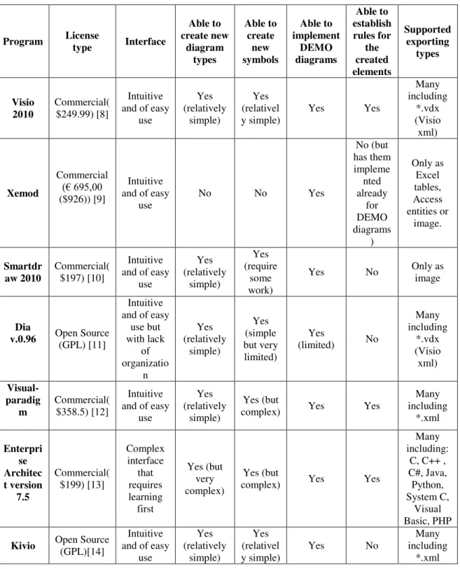
25 Table 1- Design tools analysis
Program License
type Interface Able to create new diagram types Able to create new symbols Able to implement DEMO diagrams Able to establish rules for the created elements Supported exporting types Visio 2010 Commercial( $249.99) [8] Intuitive and of easy
use Yes (relatively simple) Yes (relativel
y simple) Yes Yes
Many including *.vdx (Visio xml) Xemod Commercial (€ 695,00 ($926)) [9] Intuitive and of easy
use
No No Yes
No (but has them impleme nted already for DEMO diagrams ) Only as Excel tables, Access entities or image. Smartdr aw 2010 Commercial( $197) [10] Intuitive and of easy
use Yes (relatively simple) Yes (require some work)
Yes No Only as image
Dia
v.0.96 Open Source (GPL) [11]
Intuitive and of easy
use but with lack of organizatio n Yes (relatively simple) Yes (simple but very limited) Yes
(limited) No
Many including *.vdx (Visio xml) Visual-paradig m Commercial( $358.5) [12] Intuitive and of easy
use
Yes (relatively
simple)
Yes (but
complex) Yes Yes
Many including *.xml Enterpri se Architec t version 7.5 Commercial( $199) [13] Complex interface that requires learning first Yes (but very complex) Yes (but
complex) Yes Yes
Many including:
C, C++ , C#, Java, Python, System C,
Visual Basic, PHP
Kivio Open Source (GPL)[14]
Intuitive and of easy
use Yes (relatively simple) Yes (relativel y simple)
26
3.
I
mplementation
3.1.
Example Case Used
To illustrate the implementation of our prototype we a library scenario taken from
Enterprise Ontology - Dietz, 2006[1] will be used. Our main focus will be on the Actor
Transaction Diagram (ATD) and the Object Fact Diagram (OFD) represented below as these are the two main diagrams in the DEMO Methodology. The solution diagrams presented in Enterprise Ontology - Dietz, 2006[1] were remade using a more recent
notation available in Way of Working - Dietz, 2009[5].
27
Image 21: Library OFD Diagram (Visio)
3.2.
Validation rules for diagrams
One other thing that was analyzed was the possibility to apply specific rules to the diagrams, such as an internal actor can only execute one transaction. Those kinds of
rules are already “built in” in Xemod, and are doable in Visio 2010; however in the open source alternatives (Kivio and Dia) it is not possible to implement them, therefore the idea was set on hold.
3.3.
Changes in the DEMO Meta model
28
Image 1: Proposition for the DEMO Meta Construction Model
29
30
Image 24: DEMO Meta Process Model
Image 25: DEMO Meta Action Model
3.4.
XML implementation of ATD and OFD diagrams
It was theme of a Master’s thesis in computer science by Yan Wang the “transformation of DEMO models into exchangeable format”[21]; here we gather those ideas of how to
transform the DEMO methodology into XML and try to put them in a practical creation (with the respective changes to accommodate the Meta model differences). In that thesis
it’s studied how to transform without loss each of the four models that compose the
DEMO into a XML document. This is a valuable contribution to this thesis because it gives a starting point about how to transform the XML received from the designing tool into something that we know to have all the needed data to recreate that diagram somewhere else, in this case Media Wiki.
3.5.
Stencils Implementation
When testing new tools for a possible implementation of DEMO diagrams there was the need to try to recreate the shapes we were going to use on them. A complete stencil set
was already available for Visio and for Xemod but for all the others such thing didn’t
exist. Being Visio and the open source tools (Dia and Kivio) the three tools more likely to be explored, the first for offering the most potentiality, the second for being the free tool with most potential for Windows users and the third for being the free tool with most potential but limited to Linux, there was the need to replicate the stencil sets for the open source tools in order to fully explore their potential.
3.6.
Xemod Implementation
31
Unlike all the others design tools we tried, Xemod was specifically design for DEMO, and as such it was not only limited to diagrams, but instead allowed to implement the whole process.
Now even this software had its setbacks, in the Transaction Result Table, after having creating a result, his cardinality could not be changed, making it impossible to convert a binary result into a unary result and vice-versa. Other than this, while designing the PSD diagram, if a connecting mistake was made, the program just stopped responding instead of giving an error message.
After the whole process of implementing our Library example in Xemod, we exported it to access database format. Then we could do a detailed analysis to every table that was necessary to indentify each process, especially those related with the diagram steps, and how they related the facts.
Image 26: Access database of Library exported from Xemod
But as we previously though, in neither the exportable formats it was possible to recreate any sort of diagram, as we only had the content of the shapes and their connections. We lacked the information about their positions, sizes or connection places.
3.7.
DIA Implementation
In DIA, the software offers the option to create its own shapes in it and latter use them, and so it was done for the ATD. For our basic stencil we created the shapes of an Actor, Composite Actor, Transaction and Boundary.
32
we had to adapt the diagram shapes to a single text field. This limitation would however be very problematic if we decided to implement the OFD diagram.
The second problem encountered in the shapes creation was the fact that unless you did a mouse-over, you had no labeling on the shapes, making for example a boundary and an actor virtually undistinguished by sight. But still, this was not a major flaw, and work could proceed.
The third problem was the fact that it was impossible to create connectors, so the connectors used in our diagram would have to be the default connector changing then, if existed for that case, the tip to the desired shape. This would mean that the diagram designer would have to know the notation for each connector in order to make a complying diagram.
With all four starting shapes created, we needed to create a stencil. This was an easy
process, we just had to go to the “sheets and objects” option in the “File” tab, and create
a new stencil, were we gave it a name and a small description.
Image 27: DIA Stencil Creation
Now, to add the shapes, the process was exactly the same, but the selected option would be the first, “Shape SVG” and then search for the shape file previously created. DIA does not allow multiple importations at once, so this step has to be done for every shape you intend to use in each stencil.
When we started to create our diagram, two new problems were found, the first was the fact that, when the text exceeded his preset delimitation, the shapes would grow out of proportion, reaching huge sizes when compared to everything else, and the second was that to apply the boundary we needed to work with layers, as although shapes with no filling are possible, to select the ones in the back, they can’t be under anything, nor you
33
Image 28: DIA Implementation of Library ATD
More problems were found during and after the implementation. The program crashed often when placing shapes on the drawing board, and if by any reason you tried to open this diagram in another computer with DIA installed but without the stencil set in place, the shapes would not appear.
34
However DIA had a major issue that led to its abandon, the fact that we couldn’t relate
the connected shapes, making it impossible to use unless relaying fully on coordinates.
With this, the work was focused on Kivio.
3.8.
Kivio Implementation
Unlike Dia, in Kivio, the new shapes cannot be created in the software itself; instead, there is paid software for that purpose. But there is a second solution, which is to code the shapes with no graphical help simply by using Kivio’s xml language in a notepad.
This second solution was the one followed.
The first step here was to create a new folder for our diagrams methodology in the
shapes folder of Kivio, in this case, one named “DEMO”. In there we could create the subfolders for each of the diagrams such as one for ATD and one for OFD, but in the
same folder we have a need for a “desc” (description) file that contains the info about
our set of diagrams and as an option we can add an image to represent that very same main set.
This “desc” file is written in XML using Kivio’s tag sets and contained the following simple information:
<?xml version="1.0"?>
<KivioStencilSpawnerSetCollection> <Title data="DEMO Diagrams"/> <Id data="Kivio - DEMO Diagrams"/> </KivioStencilSpawnerSetCollection>
Now, inside each diagram folder (such as ATD) we have tree kinds of files:
1. The “desc” file, simple as the first one, in this case containing the following:
<?xml version="1.0"?> <KivioStencilSpawnerSet>
<Title data="Actor Transaction Diagram Shapes"/>
<Id data="Duarte Pinto - Actor Transaction Diagram Shapes I"/>
<Description>the basic stencils needed to create Actor Transaction Diagrams </Description>
</KivioStencilSpawnerSet>
2. An optional image *.xpm file for each shape.
3. And a *.sml file for each shape containing its data. Kivio’s XLM recognizes
35 <?xml version="1.0"?>
<KivioShapeStencil creator="Duarte"> <KivioSMLStencilSpawnerInfo>
<Author data="Duarte Pinto"/> <Title data="Composite Actor"/> <Id data="CompositeActor"/>
<Description data="ATD Composite Actor"/> <Version data="0.1"/>
<Web data="www.koffice.org"/> <Email data="[email protected]"/>
<Copyright data="Copyright (C) 2010 Duarte Pinto. All rights reserved."/> <AutoUpdate data="off"/>
</KivioSMLStencilSpawnerInfo> <Dimensions w="72.0" h="54.0"/> <KivioConnectorTarget x="0.0" y="0.0"/> <KivioConnectorTarget x="36.0" y="0.0"/> <KivioConnectorTarget x="72.0" y="0.0"/> <KivioConnectorTarget x="72.0" y="27.0"/> <KivioConnectorTarget x="72.0" y="54.0"/> <KivioConnectorTarget x="36.0" y="54.0"/> <KivioConnectorTarget x="0.0" y="54.0"/> <KivioConnectorTarget x="0.0" y="27.0"/>
<KivioShape type="Rectangle" name="CompositeActor" x="0.0" y="0.0" w="72.0" h="54.0"> <KivioFillStyle colorStyle="1" color="#736F6E"/>
</KivioShape>
<KivioShape type="TextBox" name="Text" x="0.0" y="0.0" w="72.0" h="54.0"/> </KivioShapeStencil>
By manipulating this code, it was possible to create the stencil sets for ATD and the OFD that will be then used for further develop of this thesis.
36
After having the stencils, the ATD and OFD diagram implementation in Kivio was straight forward.
Image 31: Library representation in Kivio
In the OFD there were some minor changes to the notations like the result type number being moved to under the shape as placing the text on the top right corner of the shape was not possible due to shape size constrains.
3.8.1.Kivio PHP parser
The PHP parser is the practical implementation of the previous point, the first objective was to get the raw XML from the design tool and transform it into a format that can be understood, in this case, the one proposed by Yan Wang on Transformation of DEMO models into exchangeable format thesis. Later, this new formatted XML would be used to automatically generate Semantic Media Wiki pages that represent the whole information contained in the diagrams but in an easy to understand/update format that any member of the organization can use.
The PHP code of this parser can be found in full size on the appendixes of this thesis.
3.8.2.Kivio problems
Although a viable solution Kivio also had its issues, the first being the text fields limitation. After being set the size in the stencil, if the text field by any reason is insufficient to the text itself makes part of it not to become visible. This is a major issue in diagram interpretation.
37
Kivio development by KOffice had also been placed on hold, making his compatibility with future OS and formats another problem to be considered.
Finally there was the clutter in the exported file, although not as much as a exported *vdx file from Visio, it was still a great amount that had to be filtered in every shape and connector in order to acquire only the valuable info for our task at hand.
For these reasons we decided to place Kivio on hold and try Visio to see if it was a better candidate. This does not mean Kivio was not still a possible free solution to the problem, but perhaps was not the better equipped tool to allow us a fast development with a great margin for progression.
3.9.
Visio Implementation
In Visio we had part of the work already done, as stencils for DEMO diagrams modeling were already available. The other plus side of working with Visio is that it was not a first impression with the tool; it had been used many times throughout the years by us including DEMO modeling itself. Still as every other tool in this case there were issues to solve
The first problem to solve, after the implementation of example diagrams of each type we were working at (ATD and OFD), was how to access the information relative to each shape.
Visio, as mentioned before, has already and export preset for xml, the *.vdx format, but there is a huge problem with this, there is absolutely no formatting on the output, and the amount of unneeded clutter is huge. Just to leave a general idea, to an export from our OFD model we obtained 1627 XML lines, reaching some of these lines some astonishing 741318 characters.
Just like it had been done in Kivio the first step here was to filter the variables we actually needed from the files, for that a PHP parser was created that striped the file from most of its clutter. After a while this task were starting to be overwhelming, so the search for an easier solution began.
The solution found was to use (VBA) Visual Basic for Applications. VBA is an
implementation of Microsoft’s Visual Basic that is available in the Microsoft Office Programs and also in Visio. In each application you can use it by creating a macro and it allows you to access in the case of Visio, pretty much everything that is on your
diagram, may it be property’s, coordinates, linked shapes, connector points, and so on, the list continues for a long, long amount of properties.
38
At this point one of the main questions arisen, what did we exactly need so we had enough information to create the Semantic Media Wiki pages for each shape, but also, to then recreate this exact same diagram elsewhere.
To accomplish such task the way encountered was to create a “Universal Visio Meta
Model for DEMO” that would fit any possible diagram in DEMO and also new
diagrams, shapes and connections, that not existing yet maybe be a solution to future developments.
The need for it to be abstract enough to include everything but still concrete enough to set boundaries was clear, so we did our best to accomplish it.
3.9.1.PSD Stencil
Unlike the ATD and OFD, the PSD stencil available for Visio was out of date, and did not comply with the new notation used in (Way of Working - Dietz, 2009).
For that reason we decided to build our own to comply with the PSD representations available in such document. The following image shows all the shapes that were created in the new stencil in so that it considered all the possible needs in the new notation.
39
3.9.2.Universal Visio Meta Model for DEMO
The main purpose of this Universal Visio Metal Model for DEMO (UVMMD) was to serve as to guideline to what information was really relevant in a diagram and provide the necessary base in case any new diagrams were added to the DEMO methodology. This model was specified using the World Ontology Specification Language (WOSL) and it will be presented in segments due to the obvious size constrains that we have to follow. To help acknowledge those segments the full diagram is presented bellow with the parts numbered with the other they will be explained.
40
Image 34: Universal Visio Meta Model for DEMO – Part 1
Object class “Shape” – All diagrams are composed by shapes, they are the key of representation. This object class “Shape” is a concrete representation of the abstract
concept object class “Shape Type” that we will see further ahead. An example of this could be in an ATD diagram the “Composite Actor 8” of the shape type Composite Actor. For us “Composite Actor 8” tells very little as we confine on shape properties like name to identify them but this is the way shapes are identified in the inner works of Visio.
Binary fact type [Shape] is part of [Shape] - A shape can be part of another shape,
making a greater agglomerate of shapes, but still itself a shape. As an example of this we have the OFD Fact Type that is composed by one or multiple fact roles like the fact type [PERSON] is member in [MEMBERSHIP] composed by the fact roles [PERSON]
and [MEMBERSHIP].
Binary fact type [Property] of [Shape] – Every Shape has properties; these properties
may vary between shapes, but can also be shared by multiple shapes. Using our library OFD diagram as an example of this binary fact type, we can think of “[PERSON] is
member in [MEMBERSHIP]” a property of the property type formulation that belongs
to the shape “Binary fact type 193” (being “Binary fact type 193” the shape of the shape
type Binary fact type represented in that diagram).
Binary fact type [Shape] of [Diagram] – Shapes are part of a greater picture, in our case
41
Object class “Diagram” – The Object Class “Diagram” is the concrete representation of the abstract concept object class “Diagram Type”. An example of such representation
would be “Library OFD” or even “Universal Visio Meta Model for Demo”.
Binary fact type [Diagram] is an instance of [Diagram type] – When modeling a diagram, we don’t usually randomly pick a set of shapes and connectors to use, in most
cases there are preset “templates”, and this is what is being represented in this relation.
As an example this “Library OFD” or even “Universal Visio Meta Model for Demo” are
instances of the diagram type OFD.
Image 35: Universal Visio Meta Model for DEMO – Part 2
Binary fact type [Shape] represents [Organization Artifact] – In this Binary fact type
we enter the DEMO context of our modeling. An organization artifact is a “rule of
application” for a shape or a connector. For this Binary fact type an example could be in an ATD diagram actor 183 (a shape of the shape type actor with the label “Board”) represents actor 183 initiates 12 transaction 97 (a shape of the shape type transaction
with the label “Reduced Fee Approval”)
Object class “Diagram Type” - Diagram type is the “template” behind the diagram, as we’ve seen before an example of this object class would be OFD, ATD or PSD.
Binary fact type [Shape Type] is allowed in [Diagram Type] – This Binary fact type
validates the usage of shapes in a diagram, this and [Connector Type] is allowed in [Diagram Type] are two very important steps to have a clear stencil for each diagram.
An example of this Binary fact type could be “Object Class” is allowed in “OFD”.
Binary fact type [Connector Type] is allowed in [Diagram Type] – This Binary fact
type is nearly the same as the previous, but instead of shapes it validates the allowed