SOME STUDIES ON MANUFACTURING
AND ASSEMBLY ASPECTS OF
MINIATURE J-T COOLERS WITH
SPECIFIC REGARD TO THE
PERFORMANCE FOR SMALL HEAT
LOADS
RAVEESH KUMAR¶*
Research Scholar, U.S.E.T., Guru Gobind Singh Indraprastha University, Delhi, India and Scientist, Laser Science & Technology Centre, Metcalfe House, Delhi -110054, India
SACHIN MAHESHWARI≠
Division of Manufacturing Processes & Automation Engineering, NSIT, Dwarka, New Delhi, India
CHITRA SHARMA
Department of Mechanical & Automation Engineering, GGS IP University, Kashmere Gate, Delhi 110006
Abstract:
Joule – Thomson miniature coolers are well known for their instant cooling characteristics & reliable but simple operation. Material selection and fabrication methodology play a significant role in their performance. It has been experienced during the present study that even in slight change in tolerance, allowance, fabrication techniques and integration methodology affect the performance despite keeping other parameters viz. coiled length, orifice diameter, operating pressure etc. same . In this paper, an attempt has been made to study these aspects with specific reference to fabrication & assembly for their reliable performance.
Keyword; bJoule -Thomson, Miniature cooler, Fabrication.
1. Introduction
Miniature finned tube J-T coolers are widely used for spot cooling to get optimized performance of infra red detectors needing cryogenic cooling of the order of 80 K. J-T coolers are based on Joule –Thomson effect named after two British scientist J.P.Joule & William Thomson ( later became Lord Kelvin), who discovered this very simple but useful principle in 1850. The change in the temperature is due to change in pressure at constant enthalpy and fluid temperature at the time of expansion. For obtaining cooling, this temperature must be below the inversion temperature of working fluid. The design of miniature cooler is based upon requirements of temperature to be achieved, required refrigeration capacity & cool down time. The configuration bore size of Dewar- Sensor module and the Gas flow dictates the physical size of miniature cooler, heat exchanger length, expansion orifice diameter etc. Fixed orifice J-T Coolers designed to meet requirements of 1 W refrigeration capacity at 80 K , average flow rate of 11 Litres / min & cooling time of 30 seconds at no load were found to give degraded performance due to variation in fabrication details. Degraded performance in terms of cooling time and flow rates generally lead to delayed response of sensor and increased consumption of gas necessitating bigger gas reservoir & thus limiting the system
utilization in the field conditions. Since the entire cooler assembly is small & all characteristic dimensions are in millimeters (nearly 8 mm diameter, 50mm long), these demand precision in the order of few microns.
2. Description
A finned tube miniature Joule Thomson cooler comprises of following components and is shown in fig.1 Inlet Port with Inline filter
Finned Tube Heat Exchanger Mandrel
Sealing Thread Outlet port Expansion Orifice
Fig.1: A finned tube miniature Joule Thomson cooler
2.1 Inlet Port
This is a metallic (SS304) block which facilitates entry of the working fluid from high pressure reservoir to heat exchanger. It’s interface to match with inlet piping. It is rigidly attached with mandrel. The inlet port contains a sintered Bronze / S.S filter (Pore Size: 5 microns, Porosity ~75%) to prevent passage of solid
particles in the gas stream. The filter is located in such a way that gas surely passes through it and does not sneak through its sides. One end of the finned tubing is attachéd to it through a 0.5mm hole on it.
2.2 Finned Tube Heat Exchanger
The heat exchanger is the heart of cooler. It is basically a fine bore Cupro- Nickel tubing (70/30) with spirally wound copper fins, wound closely over a mandrel of desired length. Copper fins, which are soldered to base tube, provide high thermal conductivity and facilitates efficient heat transfer and Cupro- Nickel material of the base tube helps in providing flexibility and strength. The typical dimensions of finned tube are as below.
Bore size : 0.30 mm
Tube Outer diameter : 0.45 mm Overall Finned tube diameter : 1.04 mm Fin height: 0.31 mm
Fin thickness : 0.075 mm Fin density: 105 fins/ inch.
2.3Mandrel
Light weight
Low thermal conductivity Easy to machine
Reasonably good mechanical strength
Mandrel can be made from hollow stainless steel tube but making grooves on it and having minimum thermal mass are two opposite requirements. Thus several insulating materials, such as Teflon (PTFE), Hylam (Fabric reinforced plastic) & Micarta (Melamine, Phenolics and Polyester) were considered. Teflon has good ductility and easy to machine but it was not selected on account of high heat capacity , which may increase thermal mass thus adversely affecting cool down requirements.. Hyalm has all requisite thermal properties but developed cracks while making grooves on it. Micarta is a composite of melamine, Phenolics and polyester reinforced with paper, cloth or glass fiber. Considering its commercial availability, cloth based Micarta in the form of rod was chosen .It has fine weave, possesses good mechanical strength, moisture resistance, toughness, machining properties and smooth surface appearance. When compared with stainless steel, micarta is 1/5 in density, 1/10 in thermal conductivity and 1/6 in strength. In order to provide good mechanical strength, small heat capacity & minimum axial conduction, the mandrel was provided sufficient thickness and made partially hollow.
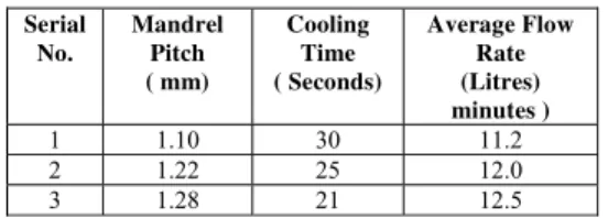
Threaded grooves with suitable pitch on the mandrel were made to ensure uniform axial spacing between the coils, V shape tool of included angle of 60 ° was used to provide proper depth of grooves. Three different groove pitches e.g. 1.10, 1.20, 1.28 were experimentally tried but 1.1 mm pitch was finalized to ensure sufficient gap between two coils for preventing thermal short circuiting between coils. Observed performance of cooler with above groove pitch is shown in table 1.
Table 1 Serial No. Mandrel Pitch ( mm) Cooling Time ( Seconds) Average Flow Rate (Litres) minutes )
1 1.10 30 11.2
2 1.22 25 12.0
3 1.28 21 12.5
The machining of the mandrel of micarta posed some special problems viz. coming out of reinforcements, thus making the surface rough and uneven. This made the root diameter non uniform & resulted in non uniformity in diameter of heat exchanger assembly. By choice of machining speed, feed and depth, a high dimensional accuracy of 0.05 mm in diameter was achieved.
2.4 Sealing Thread
A sealing thread is used in between the two coils of heat exchanger. The thread is useful in following ways.
1. It does not allow expanded gas to channel along the side walls of the mandrel and the Dewar, thus forcing the return gas to flow over the fins.
2. It keeps the coils of finned tube in their position, thus provide ruggedness to miniature cooler.
3. It accommodates slight variation in the inner diameter of the Dewar, thus keeping the heat exchanger assembly snuggedly fitted in the Dewar.
The diameter of the thread used is 0.35, 0.42 & 0.5 mm. About half of the thread thickness sits in the inter coil gap, while remaining projects out. This helps in accommodation of mini cooler in the Dewar. Three varieties of sealing threads viz Silk, Nylon and cotton were tried but best sealing action between Cooler & Dewar and maximum flexibility was provided by cotton thread. Typical experimental observations are shown in table 2
Table 2 Serial No. Sealing thread diameter ( mm) Cooling Time (seconds) Average Flow Rate (Litres/ minutes )
2.5 Outlet Port
This component connects the other end of finned tube to the expansion orifice. It is of brass and has all appropriate interface connections. A hole of 0.5 mm diameter is drilled on its surface to connect the end of finned tube. The size of outlet port should be matching with bore diameter of base tube .If it is more, there is a possibility of expansion in it before the actual expansion in the orifice.
2.6 Expansion Orifice
Another critical component of J-T cooler assembly is expansion orifice. It is generally of the order of 50±20
μ dia in the flow path of incoming high pressure stream. Through this, pre cooled high pressure gas expands irreversibly to produce a liquid-vapor mixture at slight above atmospheric pressure. For reproducible performance, orifice should be of definite regular shape. Circular shape is preferred over other shape as non circular shape has a possibility of clogging over a period of time due to presence of solid particle or molecules of Carbon di Oxide/Moisture present in the gas stream. Following options were attempted
Overlapping of various steel wire mesh Pinching off the bare end of the finned tube
Reducing the diameter of bare tube by inserting the wire Injection needles
Drilling a hole by spark erosion/Mechanical drill/LASER
Commercially available injection needles of smallest size (100-150 μ) were tried but they were found to be larger than the required. Pinching off the bare tube, steel wire mesh, wire insert type did not give reproducibility though it was possible to control the flow. Spark erosion technique could give the orifice of the order of 80 -100 μ but these were found to be of tapered shape. Orifices drilled by Laser or mechanical drill in a brass cylinder with one end closed were found to be reproducible and circular in the accuracy of ± 2 μ. An Nd- Glass commercial Laser of Kilowatt power level, CW, 1054 nm wave length gave near perfect circular hole.
2.7 Integration of Miniature Cooler
All the components were fabricated as per their drawings according to their tolerances; these were inspected for their dimensions, finish etc. by appropriate measuring instruments and cleaned by using inert chemical solutions and ultrasonically. These were then assembled in a clean room of class 10000 in following fashion.
i) Place the inline filter in the inlet port.
ii) Push the Inlet port & outlet port inside the two ends of mandrel.
iii) Insert the connecting pins to provide robustness of this assembly.
iv) The finned tube is soldered on the inlet port at one end, wound tightly on the mandrel & the other end is inserted in to the hole of outlet port and the soldered. The problem of choking of finned tube with solder was solved by inserting a stainless steel wire of 0.25 mm diameter in the finned tube and slowly taking it out during soldering process. For soldering, a special flux of zinc chloride mixed in the HCl acid was used. It is essential to complete soldering joint in first attempt as re –soldering shall invariably leads to poor joint quality.
v) Cotton thread between the coils was then wound with uniform tightness over the entire length. One end of the thread was first tied around the tip of the mandrel and is permanently attached using general adhesive e.g. Elfy. Other end was then tied and fixed to the outlet port. Cotton thread has a tendency to absorb moisture from the environment which may increase the overall diameter of the assembly. This problem is overcome by drying the assembly in the oven and the storing in a desiccator.
vi) Expansion orifice on the outer threads of outlet port was placed.
vii) Diameter of miniature cooler assembly was measured.. It should be within ± 0.02 mm. if not in this range, re wind the thread. If not again, change the sealing thread.
3. Results & Discussion
From the observations in table 1, it is seen that cooler with pitch of 1.1 mm gave the desired performance in terms of cooling time and flow rate. Achieving the desired performance with 1.1 mm pitch could have been possible due to lesser thermal mass as the cooler is shorter in length.
Similarly table 2 indicates that cooler with sealing thread of 0.42 mm has performed well .Performance with 0.35 mm gave better cooling time but it is at the cost of higher flow rate which shall lead to shorter field usage. This could be due to availability of increased flow passage between cooler & Dewar. On the other hand, lower flow rate was observed for 0.5 mm thread but cooling time is 25% more than the requirement. Lower flow rate is generally a positive factor but in this case, this is due to oversize of cooler diameter which may require extra torque for cooler Dewar assembly.
It is also experienced that miniature cooler with micarta mandrel with groove angle of 60 °, nearly circular orifice, inline sintered bronze filter in the inlet port is preferred over other options.
4. Conclusions
From the discussion and experimental findings, it is evident that a miniature cooler assembly with reliable performance in its service life was designed and developed to meet the functional requirements.
Acknowledgement
The authors are highly obliged to Sh. A.K. Maini, Director Laser Science & Technology Centre, Delhi for constant encouragement and permission to publish this work.
References
[1] Garvey Steve and Little ,W.A The potential for integrating micro miniature refrigeration in to hybrid electronic packages International journal of hybrid microelectronics (1982) vol.4 p 296
[2] Little ,W.A Integrated cryogenic chip carriers for high speed CMOS and super conducting devices ,Electrochemical society Pennington (1987) p251-259
[3] Kumar et al, Filteration aspects of J-T based cryogenic system elements Proceedings of National symposium of cryogenics, Jan 2-4, (1991), IIT Kharagpur
[4] Vonk, G. A new type of compact heat exchanger with high thermal efficiency Adv.in Cyogenic Engg (1968) 13,582-589
[5] G.Venkatratnam & S F.. PradeepNarayan Performance of a counterflow heat exchanger with longitudinal heat conduction through the wall separating the fluids from the environment. Cryogenics Vol 39 ,(1999) Oct. p811-819
[6] S. PradeepNarayanan & G.Venkatratnam Performance degradation due to longitudinal heat conduction in very high NTU counter flow heat exchanger ,Cryogenics Vol.38,Issue 9 , (1998) p 927-930
[7] Pradeep Gupta and Attrey M.D. Performance evaluation of counterflow heat exchanger considering the effect of heat in leak and longitudinal conduction for low temperature applications . Cryogenics ,Vol.40,Issue 7 , (2000) p 469-474
[8] Art Boman & David Doty, Design & manufacture of ultra low mass cryogenic heat exchangers Cryogenics Vol.41,Issue 11-12 , (2001) p 845-849
[9] E.D.Marquardt Cryocooler reliability issues for space applications Cryogenics Vol.41,Issue 11-12 , (2001) p 851-863