Noise Harshness and Vibration Characterization of Switched
Reluctance Motors
RUSU Tiberiu
1, POP Adrian-Cornel
2, SZABÓ Loránd
11Technical University of Cluj-Napoca, Romania, Department of Electrical Machines and Drives, 28 Memorandumului str., 400114 Cluj-Napoca, Romania E-mail: [email protected] , [email protected]
2Brose Fahrzeugteile GmbH&Co. KG, Germany, Advanced Development Group, Ohmstraße 2a, 97076 Würzburg, Germany
E-mail: [email protected]
Abstract – The paper deals with the multiphysic co-simulation for noise prediction of a 12/8 switched reluctance motor (SRM). Its electromagnetic analysis was performed by means of a finite element analysis (FEA) model externally coupled to a voltage-fed electrical circuit. The latter uses pre-calculated optimal values for the commutation angles and the reference current, which are provided by the dynamic model previously created in Simulink, where the closed-loop control system and the power converter are considered. The electromagnetic forces acting on each tooth of the SRM are calculated via the Maxwell stress tensor, and the Fast Fourier Transform (FFT) is applied to obtain their harmonic contents. These are then used as inputs for the harmonic structural model (HSM). The acoustic performance of the SRM is analyzed using the displacements and velocities obtained from the HSM. By means of this complex software tool the influence of the different geometrical, electrical or mechanical parameters on the vibroacoustic behavior of the SRM can be analyzed.
Keywords: switched reluctance motor, vibroacoustic behavior, noise harshness and vibration (NHV) characterization, electrical circuit coupled FE Electromagnetic Model.
I. INTRODUCTION
At the present time an advanced vehicle has dozens of electrical machines in its structure. Most of them are brushed dc machines due to their mature technology and easy controllability as well as relatively lower costs. But they have several disadvantages, mainly in conjunction with its commutator and brushes [1], [2]. Therefore intensive research efforts are made to replace these machines with others having simpler construction and higher efficiency.
A competitive candidate for automotive applications is the switched reluctance motor (SRM),
both for traction purposes and car auxiliaries. The latter applications are related to safety (as steering and brakes), comfort (as heat, ventilation and air conditioning, windows, mirrors and seats actuation, etc.), or drive train (as clutch and shift actuation, pumps, engine cooling fan). A general overview of the most typical automotive electric drive applications are given in Fig. 1.
Fig. 1. Overview of automotive electric drives applications [1].
The SRMs could be a very good choice for some of these applications due to their advantages, such as a very robust structure, easy and cheap manufacturing, prominent fault tolerance, high controllable starting torque and wide-speed range [3], [4]. However they have some drawbacks, among them the higher vibrations and noise, which is a major disadvantage in automotive applications [5], [6], [7].
Vibration and acoustic noise related issues can be addressed in the case of the SRMs by using special designs [8], [9], advanced control techniques [10] such as neural networks [11] or fuzzy logic control [12].
consider the vibroacoustic behavior of the SRM in an optimization loop [14].
Today's design challenges can't be addressed without advanced simulation tools. Trying to solve the enormous engineering problems connected to automotive applications, the use of standard, ad-hoc design methodologies, or physical testing alone would be prohibitively inefficient and expensive. But accurate simulation software can efficiently combine diverse engineering skills (as electromagnetic, mechanical, noise and vibrations, etc.) [17].
For the vibroacoustic study of the SRM a multiphysic model was developed. At first, the electromagnetic model of the machine was created, to obtain the flux and torque characteristics which have to be used in the dynamic model for calculating the optimal control parameters of the drive. These models are used in combination with mechanical simulation systems. The noise harshness and vibration (NHV) behavior of the machine can be simulated by means of structural models coupled to vibroacoustic ones [18], [19], [20].
Following the introduction, in Section II theoretical insights are given for the NVH characterization of a SRM whereas in Section III the multiphysics design modeling approach is addressed. In Section IV the simulations results are reported. The conclusions are drawn in Section V.
II. THE NOISE HARSHNESS AND VIBRATION CHARACTERIZATION OF SRM
Noise and vibration are two strongly interconnected phenomena in electrical machines [21], [22]. Normally, the radiated noise is the effect of a vibrating surface. As such, sources of noise and vibration are the same [23].
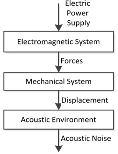
The mechanism of the energy conversion into acoustic energy in electrical machines is given in Fig. 2 [24].
Electromagnetic System
Mechanical System Forces
Acoustic Environment Displacement
Electric Power Supply
Acoustic Noise
Fig. 2. Energy conversion into acoustic energy in electrical machines.
To be able to design a low noise SRM it is crucial to understand the origins of noise and the mechanisms
which lead to NHV issues. The studies were developed initially for analyzing the noise and vibration characteristics of vehicles, particularly cars and trucks, but later they were also applied for electrical machines used in automotive applications [16].
The main origins of noise in an electrical machine can be of mechanical, aerodynamic and electromagnetic origin [23]. Power converters, in function of their topology and applied control strategies, have an effect on both mechanical and electromagnetic noise of the machine too [25].
Mechanical noise is typically due to the bearings, rotor unbalance and shaft misalignment. It also depends on the motor operating conditions. Electromagnetic noise is mainly caused by the geometry of the electrical machine and its working principle. The electromagnetic noise is mainly caused by the electromagnetic forces in the air-gap, which are due to the magnetic flux passing from the stator to the rotor [26].
In vibroacoustic analysis the air-gap forces are usually separated into tangential and radial forces. The useful forces are the tangential ones since they are producing the torque. Radial forces have to be reduced since they are producing the unwanted noises.
The force components are regularly computed by means of the Maxwell stress tensor. This is a second rank tensor representing the interaction between electromagnetic forces and mechanical momentum. In the case of electrical machines, it can be used to efficiently compute the radial and tangential force components [25]:
t r
t B B
F
0 1
µ
= (1)
(
2 2)
0 2
1
t r
r B B
F = −
µ (2)
where Br and Bt are the radial and tangential
magnetic flux densities, and µ0 the permeability of empty space.
Basically, the large radial force component acting on opposite SRM poles deform the stator yoke into diverse circumferential mode shapes at their own natural mode frequencies [26].
The displacement of the stator surface is practically responsible for the noise. Therefore, in the study of the SRM noise, the computation of the natural mode frequencies is of maximum importance.
Resonance phenomena appear when the frequency of the radial force acting on the stator matches the natural frequencies of the stator. These are causing the increased acoustic noise in the SRM.
Analytical methods for calculation of mode frequencies for a complex structure, such as a SRM, are complicated and hard to apply, and the obtained results are of low precision.
The best way to obtain the mode shapes and resonant frequencies of a given SRM is to use numeric field computation based methods combined with numeric structural analysis tools. This approach needs multiphysical modeling and advanced co-simulation tools [27], [28].
III. MULTIPHYSICAL MODELING OF THE SRM
The noise, harshness and vibration of electrical machines can be analyzed in depth by means of advanced multiphysic modeling, simulation and validation tools only [16], [20]. Therefore a comprehensive co-simulation workflow was designed, in which complex simulation platforms are coupled, as seen in Fig. 3 [28]. In the same figure, all the main components of the developed workflow together with their inputs and outputs can be easily distinguished.
Fig. 3. The co-simulation workflow.
At the first level is the Control module. At its input the reference torque, speed, and the temperature of the SRM has to be given. Using these input data and by means of the SRM torque model the current reference can be computed. This, together with electric and control parameters, serves as the input for the hysteresis current controllers, which are delivering the phase currents and voltages of the SRM.
The Electromagnetic module is the core element of the co-simulation platform and comprises the electromagnetic two dimensional (2D) finite elements (FE) model of the SRM built in ANSYS Maxwell. It is used for dynamic simulations of the machine. It uses the output signals of the previous modules, together with information related to the SRM geometry and used materials. In the frame of this module, the x- and y-axis components of the generated electromagnetic forces can be extracted, and a Fast Fourier transform (FFT) based spectrum analysis can be performed.
At the next stage the Structural harmonic model is placed. Here, based on the results of the previously performed electromagnetic analysis, in terms of exciting forces and the three dimensional (3D) SRM geometry, the total deformation of the machine at different frequencies can be computed using the structural solver of ANSYS Mechanical. The module can deliver the displacements and velocities at given exciting input radial forces.
The Acoustic model is the last element in this co-simulation workflow. It needs data on the acoustic body geometry of the SRM and velocities computed at the previous simulation platform level. The mechanical deformations are transformed into the velocity of the defined nodes. The acoustic pressure and the sound pressure level (SPL) can be computed on predetermined points or surfaces of interest. Hence, for discrete frequencies the acoustic power and sound intensity of the SRM can be also calculated.
The last three modules of the simulation platform are coupled together in the frame of ANSYS Workbench.
IV. SIMULATION RESULTS
The complex simulation workflow presented above is used to analyze a high speed three-phase 12/8 SRM designed for an electrically driven air compressor to be used in automotive applications.
The main specifications of the SRM are: •no. of phases: 3
•no. of stator/rotor poles: 12/8 •base speed: 10,000 r/min •rated torque: 6.7 N∙m •continuous power: 7 kW •maximum current: 70 A •DC bus voltage: 300 V.
for the machine in order to integrate it in the optimization loop. Such an approach was presented in details in [27]. The resulted optimized cross section of the SRM taken into study is shown in Fig. 4.
Fig. 4. Cross section of the studied SRM showing tooth tips used for force calculation.
Based on the magnetization characteristics obtained in 2D FE static analysis (i.e. flux linkage and static torque function of rotor position and phase current) a dynamic model of the SRM was developed in MATLAB/Simulink. In the dynamic model the average torque control strategy was employed and the optimal firing angles were calculated in order to minimize the torque ripple of the machine [29]. Using the same optimization scenario also other optimizations can be performed having other objectives as high efficiency or low radial forces.
A PI controller was used to regulate the torque of the machine, providing at its output the reference for the phase current. Hysteresis current control was further used, to maintain the phase currents within a band of ±2.5% of the reference current. An asymmetric bridge converter was used in the simulation and the power devices are controlled by means of a soft chopping commutation technique.
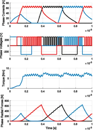
In the electromagnetic model of the SRM, the excitation of the windings was done by means of an external circuit, in which the parameters (optimal firing angles, current reference), previously calculated in the dynamic model (Simulink) were used as input parameters for the electrical circuit. This allowed a strong coupling between the electromagnetic and the electrical circuit and its control parameters. The phase currents, voltages, radial forces, and the total electromagnetic torque generated by the SRM considering dynamic simulation over a complete fundamental period can be seen in Fig. 5.
In the electromagnetic model of the SRM, tooth tips objects were created at the end of each stator pole, as shown in Fig. 4, allowing therefore the computation of the harmonic force at each tooth tip individually.
The next step in the workflow was to create the 3D geometry of the stator, to assign the materials; and to set up the boundary conditions, the mesh and the analysis parameters. In Fig. 6 one can see the mesh for the stator structure, as well as the fixed points which have been used as boundary condition, preventing the
structure from moving. The same settings were used for the modal analysis and harmonic response analysis.
Fig. 5. Results from dynamic simulations.
Fig. 6. Mesh of the 3D stator and fixed points considered as boundary condition.
A. Modal Analysis Results.
The vibration modes of the studied stator structure together with its resonant frequencies were been computed by means of modal analysis performed in ANSYS Workbench. The most important mode shapes are depicted in Fig. 7.
The dominant mode for this stator configuration is the square mode, as seen in Fig. 7a.
B. Harmonic Response Analysis Results.
the 3D structure of the SRM stator (as shown in Fig. 8), in order to perform the harmonic response analysis.
a) 7,935 Hz.
b) 8,014 Hz.
c) 8,108 Hz.
d) 9,358 Hz. Fig. 7. Modal analysis results.
Fig. 8. Remote points locations indicating forces and moments applied.
The Cartesian components of the radial forces applied to the stator tooth are shown in Fig. 9.
Fig. 9. Cartesian components of electromagnetic forces applied to a single stator tooth.
Next, the harmonic analysis was performed. The velocity profile was obtained at each single tooth of the SRM. Some results showing typical velocity at a single stator tooth are shown in Fig. 10.
Fig. 10. Velocity profile ata single stator tooth.
The total deformation of the machine structure at the fundamental frequency and at 6th harmonic obtained by means of harmonic response analysis is shown in Fig. 11.
C. Acoustic Analysis Results.
When a structure oscillates, the molecules in the surrounding air also vibrate, causing noise [30].
In order to address the acoustic behavior of the SRM, an acoustic body was created in which the mass density and sonic speed has been defined using the properties for air as a medium.
A virtual disk was used as the acoustic body, having 1 m diameter and the thickness equal to the stack length of the stator. The stator was subtracted from the geometry of the acoustic body, and the velocities calculated by means of the harmonic analysis have been mapped on the faces inside the acoustic body as shown in Fig. 12.
a) 1,333 Hz.
b) 8,000 Hz.
Fig. 11. Total deformations obtained at various frequencies.
Fig. 12. The acoustic body with the mesh and the imported velocities.
Based on the results presented in Fig. 13, one can see that the maximum SPL generated by the machine at fundamental frequency is around 86 dB near to the vibration surface (close to center point), and attenuates to approximately 63 dB at 0.5 m from the surface where the velocities are applied.
Fig. 13. Sound pressure level on the acoustic body at the fundamental frequency (1,333 Hz).
CONCLUSIONS
In the paper a multiphysics simulation approach has been detailed in order to predict the radiated noise of a SRM developed for automotive applications.
It is generally known that the main noise and vibration for a SRM is due to the radial force exerted on the stator poles, therefore the minimization of the radial force is extremely desirable.
Electromagnetic analysis of the machine carried out by means of 2D FE software has been coupled with an external circuit in order to perform dynamic simulations. Electromagnetic forces acting on each tooth of the machine were calculated both in time and frequency domain, by applying the Maxwell stress tensor method.
A modal analysis has been also conducted, and the modal shapes together with resonant frequencies of the stator have been found. These are highly important, since it is unwanted that the structure to be excited at its eigen frequencies, which could lead to acoustic reso-nance and consequently to significant noise generation.
The 3D model of the stator was developed for the structural harmonic model, and the previously obtained forces have been individually applied to each stator pole, such that the displacements and velocities acting on the structure could be computed.
An acoustic body was created and previously calculated velocities have been mapped to its surface. This way the radiated noise of the machine could be evaluated. Based on the simulated results, it was found that the maximum SPL at fundamental frequency (of 1,333.3 Hz) is around 85 dBA (near the vibration surface).
Since the workflow was developed using parametric models, optimization procedures can be conducted with the objective to reduce the radiated acoustic noise of the machine, however with the price paid in terms of needed enormous computation time.
compo-nents such as shield, housing, and other mechanical parts in order to obtain more accurate results.
REFERENCES
[1] D. Iles-Klumpner, "Automotive Permanent Magnet Brushless Actuation Technologies," Ph.D. Thesis, "Politehnica" University, Timișoara (Romania), 2005. [2] P.J. McCleer, "Electric drives for pump, fan, and
compressor loads in automotive applications," in Proceedings of the IEEE International Symposium on Industrial Electronics (ISIE '1995), Athens (Greece), 1995, pp. 80-85.
[3] K.Á. Bíró, I.A. Viorel, L. Szabó, G. Henneberger, Special Electrical Machines (in Romanian). Cluj (Romania): Mediamira, 2005.
[4] R. Krishnan, Switched Reluctance Motor Drives: Modeling, Simulation, Analysis, Design, and Applications. Boca Raton (USA): CRC, 2001.
[5] G. Henneberger, I.A. Viorel, Variable Reluctance Electrical Machines. Aachen (Germany): Shaker Verlag, 2001.
[6] T.J.E. Miller, Switched Reluctance Motors and Their Control. Hillsboro (USA): Magna Physics, 1993. [7] C. Lin, B. Fahimi, "Prediction of acoustic noise in
switched reluctance machines," in Proceedings of the 39th Annual Conference of the IEEE Industrial
Electronics Society (IECON '2013), Vienna (Austria), 2013, pp. 3060-3065.
[8] C. Pollock, C.-Y. Wu, "Acoustic noise cancellation techniques for switched reluctance drives," IEEE Transactions on Industry Applications, vol. 33,no. 2, pp. 477-484, 1997.
[9] K. Edamura, I. Miki, "Design of stator and rotor for noise reduction of SRM," in Proceedings of the 17th International Conference on Electrical Machines and Systems (ICEMS '2014), Hangzhou (China), 2014, pp. 1871-1874.
[10] J.Y. Chai, Y.W. Lin, C.M. Liaw, "Comparative study of switching controls in vibration and acoustic noise reductions for switched reluctance motor," IEE Proceedings-Electric Power Applications, vol. 153,no. 3, pp. 348-360, 2006.
[11] B. Fahimi, G. Suresh, K.M. Rahman, M. Ehsani, "Mitigation of acoustic noise and vibration in switched reluctance motor drive using neural network based current profiling," in Record of the 1998 IEEE Industry Applications Conference & 33rd IAS Annual Meeting, St. Louis (USA), 1998, pp. 715-722.
[12] M. Divandari, A. Dadpour, "Radial force and torque ripple optimization for acoustic noise reduction of SRM drives via fuzzy logic control," in Proceedings of the 9th
IEEE/IAS International Conference on Industry Applications (INDUSCON '2010), Sao Paulo (Brasil), 2010.
[13] H. Mechmeche, M. Hecquet, F. Gillon, A. Tounzi, G. Fritz, "Vibration and acoustic noise prediction in an 8/6 SRM using coupled analytical multi-physic models," in Proceedings of the XVI International Symposium on Electromagnetic Fields in Mechatronics, Electrical and Electronic Engineering (ISEF '2013), Ohrid (Macedonia), 2013.
[14] M. van der Giet, E. Lange, D.A.P. Correa, I.E. Chabu, S.I. Nabeta, K. Hameyer, "Acoustic Simulation of a Special Switched Reluctance Drive by Means of Field-Circuit Coupling and Multiphysics Simulation," IEEE
Transactions on Industrial Electronics, vol. 57, no. 9, pp. 2946-2953, 2010.
[15] X. Liang, G. Li, J. Ojeda, M. Gabsi, Z. Ren, "Comparative study of classical and mutually coupled switched reluctance motors using multiphysics finite-element modeling," IEEE Transactions on Industrial Electronics, vol. 61,no. 9, pp. 5066-5074, 2014.
[16] F.L. dos Santos, J. Anthonis, F. Naclerio, J.J. Gyselinck, H. Van der Auweraer, L.C. Goes, "Multiphysics NVH Modeling: Simulation of a Switched Reluctance Motor for an Electric Vehicle," IEEE Transactions on Industrial Electronics,, vol. 61,no. 1, pp. 469-476, 2014. [17] J.A. Vick, "Innovative design begins with simulation
software," IEEE Spectrum, vol. 51,no. 5 (May 2014), p. S2, 2014.
[18] R. Islam, I. Husain, "Analytical model for predicting noise and vibration in permanent-magnet synchronous motors," IEEE Transactions on Industry Applications, vol. 46,no. 6, pp. 2346-2354, 2010.
[19] P.J. Shorter, R. Langley, "Vibro-acoustic analysis of complex systems," Journal of Sound and Vibration, vol. 288,no. 3, pp. 669-699, 2005.
[20] B. Meek, H. Van der Auwear, K. De Langhe, "Challenges in NVH for electric vehicles," in Proceedings of the World Automotive Congress (FISITA '2012), Beijing (China), 2013, pp. 675-685.
[21] L. Timár-Peregrin, Noise and Vibration of Electrical Machines. Amsterdam (The Netherlands): Elsevier, 1989.
[22] M.L. Adams, Rotating Machinery Vibration: from Analysis to Troubleshooting. Boca Raton (USA): CRC, 2000.
[23] O. Bîrte, T. Rusu, C.S. Marţiş, L. Szabó, "A Survey on Reducing Noise and Vibrations in Some Electrical Machines Used in Automotive Applications," Scientific Bulletin of the Electrical Engineering Faculty,
University of Targoviște Wallachia (Romania), vol. 12, no. 2, pp. 19-24.
[24] J.F. Gieras, C. Wang, J.C. Lai, Noise of Polyphase Electric Motors vol. 129. Boca Raton (USA): CRC, 2005.
[25] P. Pillay, W. Cai, "An investigation into vibration in switched reluctance motors," IEEE Transactions on Industry Applications, vol. 35,no. 3, pp. 589-596, 1999. [26] K. Kasper, Analysis and Control of the Acoustic
Behavior of Switched Reluctance Drives. Aachen (Germany): Shaker Verlag Gmbh, 2011.
[27] A.-C. Pop, V. Petruş, J. Gyselinck, C. Marţiş, V. Iancu, "Finite element based multiphysics optimal design of switched reluctance motors used in electric vehicles propulsion," Journal of Computer Science and Control Systems, vol. 5,no. 1, p. 65, 2012.
[28] L. Szabó, M. Ruba, "Using co-simulations in fault tolerant machine's study," in Proceedings of the 23rd
European Conference on Modelling and Simulation (ECMS '2009), Madrid (Spain), 2009, pp. 756-762. [29] V. Petruş, A.-C. Pop, J. Gyselinck, C. Marţiş, V. Iancu,
"Average torque control of an 8/6 switched reluctance machine for electric vehicle traction," Journal of Computer Science and Control Systems, vol. 5,no. 1, pp. 59-64, 2012.
![Fig. 1. Overview of automotive electric drives applications [1].](https://thumb-eu.123doks.com/thumbv2/123dok_br/18360780.354132/1.892.478.788.598.818/fig-overview-automotive-electric-drives-applications.webp)