EFFECTS OF DIFFERENT CONTROL
PARAMETERS ON THE AVERAGE
CHARACTERISTICS OF SWITCHED
RELUCTANCE MOTOR
Mahmoud M. Elkholy
Electrical Power and Machines Department, Faculty of Engineering, Zagazig University Zagazig, Egypt
Hamid M. Elshwey
Electrical Power and Machines Department, Faculty of Engineering, Zagazig University Zagazig, Egypt
Afaf F. Abdel-kader
Electrical Power and Machines Department, Faculty of Engineering, Zagazig University Zagazig, Egypt
Abstract:
This paper is to study the effects of voltage variation, advancing the switching ON angle, Early switching OFF angle, and Freewheeling resistance on the average characteristics of switched reluctance motor over a wide range of speeds from starting to high speed. The mathematical equations necessary to calculate the average motor performance are developed. The experimental machine in this paper is composed of stator, which is 36 slots, divided into six cylindrical poles. The rotor has two salient poles without any winding.
Keywords: Switched reluctance motor, voltage control, advancing switching ON angle, early switching OFF angle and freewheeling resistance
1.Introduction
Nowadays, switched reluctance motors attract more and more attention. The switched reluctance motor is simple to construct. The stator is a salient pole with concentrated coils, or cylindrical pole with distributed coils. The rotor is a salient pole without coils or permanent magnet. SRM has series motor characteristics; this means that the motor operating point has a wide range of speed variation from low till high values. SRM is used for traction applications as low cost implementation is possible and where the torque / speed characteristics can be tailored to suit both accelerating, steady running and braking operation [1, 2]. SRM is also used for propulsion in marine without the need of mechanical connection [3].
Calculation model of the SRM, which is a general purpose, is achieved by [4], where the electric circuit and magnetic circuit of SRM are separated and are coupled by proper controlled source. An approach to automatic control of the turn-on angle is used [5] to excite the switched reluctance motor. The methods for indirect sensing of the rotor position in SRM are described [6, 7]. A detection method uses the change of the derivative of the phase current to detect the position where the rotor pole and stator pole start to overlap.
The current control requires each individual phase current to be sensed, where voltage control normally only to be senses a current sensor in the DC link for over current protection [8-10].
The advancing switching ON angle improves the transient performance characteristics of SRM [11].
This paper presents mathematical equations, which are required to calculate the average performance of SRM and introduces the method to connect motor terminal with DC supply in case of advancing the switching ON angle or early switching OFF angle. The effects of applied voltage variation, switching ON angle, early switching OFF and freewheeling circuit resistance are introduced in the paper.
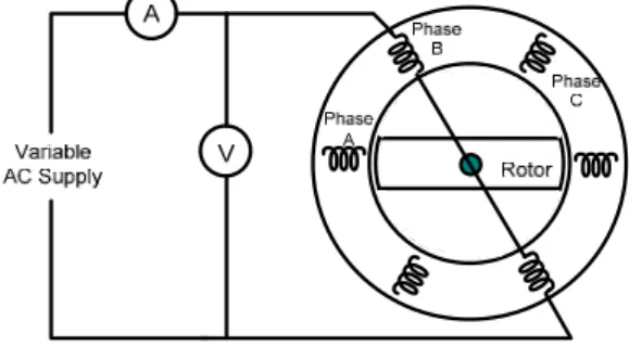
2. Experimental Machine
The rotor has two salient poles without any winding. More data are given in the Appendix. The stator windings are stator windings are wound as shown in Fig. 1.
Fig. 1. Stator windings drawing
2.1 Inductance measurements
In order to measure the phase self inductance of the constructed motor, the connected diagram of Fig. 2 is used.
Fig. 2. Connection Diagram for inductance measurements
When the phase current is passed in the motor, the rotor is rotated until reach aligned position with the supplied phase.
ph ph ph
V
/
I
Z
(1)Where,
Z
ph is phase impedance,V
phis supplied phase voltage andI
ph is the supplied phase current.The phase inductance
X
phcan be determined as:)
R
Z
(
X
ph
2ph
2 (2)Where; R is phase resistance
The phase inductance
L
phat this position and at this current is determined as:f
2
/
X
L
ph
ph
(3)Where, f is the supply frequency, which is equal to 50 Hz in this work.
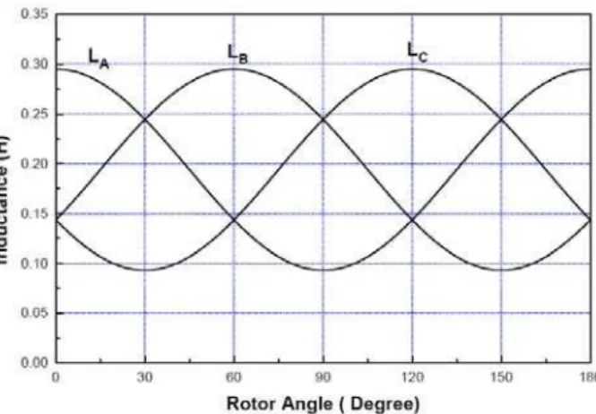
Fig. 3 Variation of phase self inductance with rotor angle at different currents
It will be noticed from Fig. 3 that the phase inductance curve is increased by decreasing the current due to saturation effect in the magnetic circuit.
3. Performance Analysis of Switched Reluctance Motor
3.1 Calculation of the motor inductance
The self inductance of phases A, B and C can be given as:
)
2
cos(
]
2
/
)
L
L
[(
]
2
/
)
L
L
[(
L
L
A
q
d
q
d
q
(4)))
2
(
2
cos(
]
2
/
)
L
L
[(
]
2
/
)
L
L
[(
L
L
B
q
d
q
d
q
s (5))) ( 2 cos( ] 2 / ) L L [( ] 2 / ) L L [( L
LC q d q d q s (6)
Where,
d
L
: Stator phase inductance at aligned positionq
L
: Stator phase inductance at unaligned position : Rotor position angle with respect to the axis of phase A
s
: Angle between two sequential stator phases and can be given as s 2/Ns
Where,
s
N : Number of stator poles which equal six of the motor under studying
Fig. 4 shows the variation of self inductances of phase A, B and C with rotor angle.
Fig. 4 Variation of phases inductances with rotor position
3.2 Calculation of the motor performance characteristics
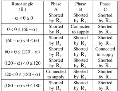
Rotor angle () Phase A Phase B Phase C 60 0
Shorted by f
R
Connected to supply Shorted by fR
12060 Shorted by
f
R
Shorted by fR
Connected to supply 180120 Connected
to supply Shorted by f
R
Shorted by fR
Table 1 Connection table without advancing switching angle
Where;
f
R
: Freewheeling circuit resistanceThe phase current is increased during conduction period (when the phase connected to supply) and the phase current is decreased during disconnection period and connected to freewheeling circuit.
It's shown that from the above table the conduction period is 60 and disconnection period is 120. When the rotor angle in the range of (060):
The current of phase B in increased and currents of phases A and C are decreased. The phases current can be given as:
fd /
t fd
max
Bi
(
I
I
)[
1
e
]
I
I
Bi Bi
(7)
Cd Cd/ t fi Cd
I
e
I
Ad Ad/ t fi Ad
I
e
I
Where,
R
/
V
I
max
V
: Voltage of dc supplyR
: Resistance of phase windingBi
: Electrical time constant of phase B and equalsL
B/
R
Bi
t
: Time starting from moment of connection and equalst
Bi
/
6
n
Where,
n
: Rotational speed rpm.Cd
t
: Time of decreased current and equals(
120
)
/
6
n
Cd
: Time constant of decreased current and equals:)
R
R
/(
L
C fCd
Ad
t
: Time of decreased current and equals(
180
)
/
6
n
Ad
: Time constant of decreased current and equals:)
R
R
/(
L
A fAd
fi
I
: is the higher value of the phase current at the end of conduction period. All phases have the same value of higher current, due to symmetrical operation of all phases.fd
I
: is the value of the phase current at the end of decreasing period when the phase is connected to freewheeling circuitWhen the rotor angle in the range of (60120):
The current of phase C in increased and currents of phases A and B are decreased. The phases current can be given as:
fd /
t fd
max
Ci
(
I
I
)[
1
e
]
I
I
Ci Ci
(8)Ad Ad/ t fi Ad
I
e
I
Bd Bd/ t fi Bd
I
e
I
Where,
Ci
Ci
t
: Time starting from moment of connection and equalst
Ci
(
60
)
/
6
n
Bd
t
: Time of decreased current and equals(
60
)
/
6
n
Bd
: Time constant of decreased current and can be given as:)
R
R
/(
L
B fBd
When the rotor angle in the range of (120 180):
The current of phase A in increased and currents of phases B and C are decreased. The phase's currents are:
fd /
t fd
max
Ai
(
I
I
)[
1
e
]
I
I
Ai Ai
(9)
Bd Bd/ t fi Bd
I
e
I
Cd Cd/ t fi Cd
I
e
I
Where,
Ai
: Electrical time constant of phase A and equalsL
A/
R
Ai
t
: Time starting from moment of connection and equalst
Ai
(
120
)
/
6
n
The supply current is equal to the current of any phases during increasing period.
180
120
at
I
I
120
60
at
I
I
60
0
at
I
I
Ai s Ci s Bi s
(10)The average value of any current is given as:
2 0 insav
I
d
2
1
I
(11)The instantaneous value of torque resulting from phase is determined as:
)
d
/
dL
(
I
5
.
0
T
A
2A A
(12))
d
/
dL
(
I
5
.
0
T
B
2B B
(13))
d
/
dL
(
I
5
.
0
T
C
C2 C
(14)The instantaneous value of total torque (
T
t) of the motor is:C B A
t
T
T
T
T
(15)The average motor torque is determined as:
20 t
av
T
d
2
1
T
(16)The instantaneous motor input power (
P
in) is given as:s in
V
I
P
(17)The instantaneous motor output power (
P
out) is given as:60
/
n
2
T
P
out
t
(18)The instantaneous motor efficiency is given as:
in out
/
P
P
(19)Rotor angle () Phase A Phase B Phase C 0 Connected to supply Connected to supply Shorted by
R
f) 60 (
0 Shorted
by
R
fConnected to supply
Shorted by
R
f60 )
60
( Shorted
by
R
fConnected to supply Connected to supply ) 120 (
60 Shorted
by
R
fShorted by
R
fConnected to supply
120 )
120
( Connected
to supply
Shorted by
R
fConnected to supply
) 180 (
120 Connected
to supply
Shorted by
R
fShorted by
R
f) 180 180
( Connected
to supply
Connected to supply
Shorted by
R
f Table 2 Connection table with advancing on switching angleThe phase conduction period to the supply is increased over than 60by the advance angle
and the disconnection angle will be reduced than 120 by the same advancing angle. During the advance angle
, the supplied phase will be in parallel with the last supplied phase as shown in Table (2). The motor currents can be calculated by the same above equations during increasing and decreasing period.When the early switching OFF technique is used, the phase is switched off before the aligned position by the angle to decrease the negative torque. Therefore, the conduction period is decreased than 60 by the switching angle and the disconnection period is increased over 120. During the early switching off method, the phases are connected to supply or to freewheeling circuit according to Table (3).
Rotor angle () Phase A Phase B Phase C 0 Shorted
by
R
fShorted by
R
fShorted by
R
f) 60 (
0 Shorted
by
R
fConnected to supply
Shorted by
R
f60 )
60
( Shorted
by
R
fShorted by
R
fShorted by
R
f) 120 (
60 Shorted
by
R
fShorted by
R
fConnected to supply
120 )
120
( Shorted
by
R
fShorted by
R
fShorted by
R
f) 180 (
120 Connected
to supply
Shorted by
R
fShorted by
R
f180 )
180
( Shorted
by
R
fShorted by
R
fShorted by
R
f Table 3 Connection table with early switching off angle4. Average Motor Characteristics
From the previous equations and with MATLAB computer program, the average motor performance characteristics are determined neglecting the saturation effect. The effects of applied voltage variation, switching ON angle, early switching OFF and freewheeling circuit resistance are given below.
4.1 Effect of applied voltage variation on average motor characteristics
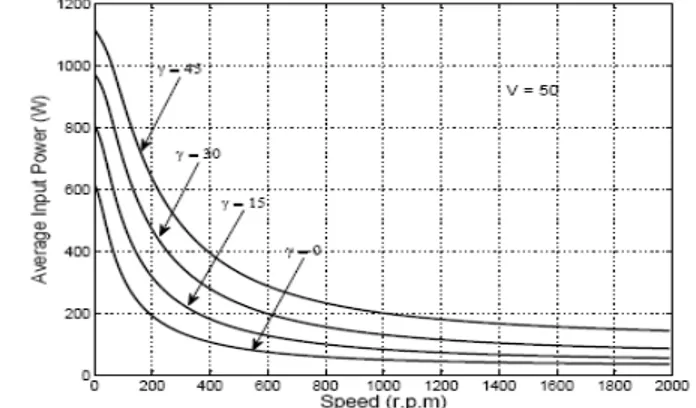
By calculating average values of performance characteristics at different speeds and at several values of applied voltages, the average motor characteristics are obtained on Figures (5) to (10).
of motor voltage. This is occurred because voltage increasing increases both positive and negative instantaneous torque.
Increasing the motor voltages as shown in Fig. (8) increases the average motor output power at low speeds. At high speeds, increasing the voltages, negatively increase the output power. The negative power is not a generating power returned to the supply, or decreased the input power, but it is a consumed power in a motor braking.
By increasing the motor voltage, the motor input power is increased at low speeds and also at high speeds, as shown in Fig. (9). The motor efficiency is varied by varying the speed, as shown in Fig. (10). The variation in supply voltage is not resulted any variation in the efficiency as shown in the figure. Because, increasing rate in the output power is equaled to the increasing rate in the input power. At high speeds, the efficiency is equaled to zero, because all of power is a consumed in the motor.
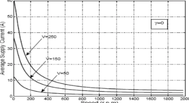
Fig. 5 Variation of supply current with speed at different values of supply voltages
Fig. 6 Variation of motor phase current with speed at different values of supply voltages
Fig. 7 Variation of total torque with speed at different values of supply voltages
Fig. 9 Variation of input power with speed at different values of supply voltages
Fig. 10 Variation of motor efficiency with speed at different values of supply voltages
4.2 Effect of advancing switching ON angle on average motor characteristics
The average performance characteristics of SRM at different speeds and at several values of advance angle
, are obtained on Figures (11) to (16).Fig. (11) shows the variation of average supply current with motor speed. When the speed is increased, for any advance angle, the current is decreased. When the advance angle is increased, the current is increased at all speeds with illustrated rates in Fig. (11). The motor phase current is varied with speed variation as shown in Fig. (12). Where, the phase current is decreased with speed increasing. At any speed, the phase current is increased by increasing the advance angle
. The SRM average torque variation with speed is similar to that of series motor as shown in Fig.(13). Increasing the advance angle, at the same voltage leads to torque increasing. Therefore, the motor availability to rotate with load at high speed will be achieved by increasing the advance angle, as shown in Fig. (13).Increasing the advance angle, leads increase the output power and input power by rates as shown in Fig. (14) and Fig.(15) respectively.
When the advance angle is equaled to zero, the efficiency is reached to zero at high speeds as shown in Fig. (16) because the output power is negative. With increasing the advance angle, the efficiency is increased with suitable values through all speeds as shown in Fig. (16).
Fig. 12 Variation of motor phase current with speed at different values of advancing switching ON angle
Fig. 13 Variation of motor torque current with speed at different values of advancing switching ON angle
Fig. 14 Variation of motor output power with speed at different values of advancing switching ON angle
Fig. 16 Variation of motor efficiency with speed at different values of advancing switching ON angle
4.3 Effect of early switching OFF angle on average motor characteristics
The average performance characteristics of SRM are determined when the motor speed is varied from 0 to 3000 rpm, at several values of early switching off angle
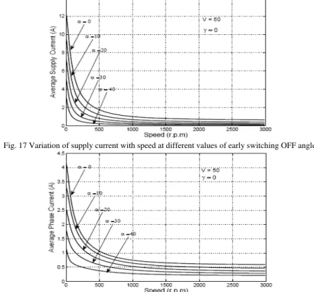
in figures from Fig. (17) to Fig. (22).Fig. (17) shows the average supply current variation at different values of angle
. Increasing the angle
decreases the supply current. The motor phase current is also decreased by increasing angle
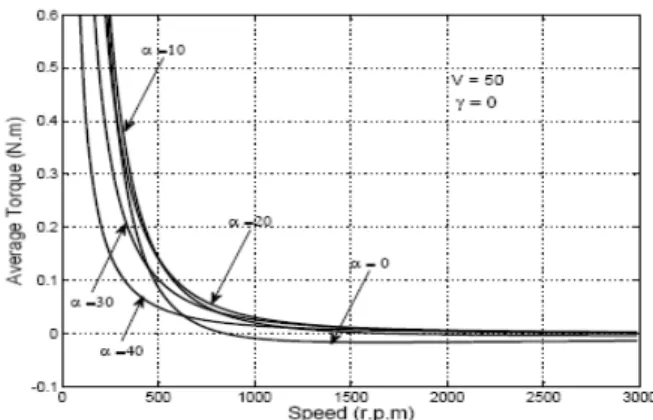
as shown in Fig. (18).Fig. (19) shows the average torque variation with motor speed. The torque is high with small value of the angle
. Reversely, increasing the angle
at high speeds increases the torque.The output power is increased by decreasing the angle
at low speeds. But, increasing the angle
at high speeds increases the output power as shown in Fig. (20).The input power is decreased by increasing the angle
at low speeds or at high speeds, as shown in Fig. (21). The variation of motor efficiency with speed at different values of angle
is shown in Fig. (22).Fig. 17 Variation of supply current with speed at different values of early switching OFF angle
Fig. 19 Variation of motor torque with speed at different values of early switching OFF angle
Fig. 20 Variation of output power with speed at different values of early switching OFF angle
Fig. 21 Variation of input power with speed at different values of early switching OFF angle
Fig. 22 Variation of motor efficiency with speed at different values of early switching OFF angle
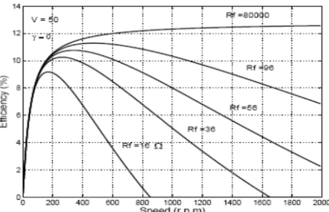
4.4 Effect of freewheeling circuit resistance on average motor characteristics
current, because phase windings are disconnected from the supply when the current is passed through the freewheeling circuit. Also, varying the resistance Rf doesn't vary the motor input power.
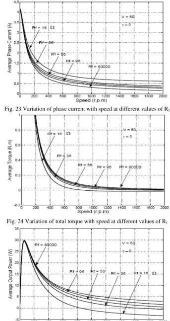
Increasing the resistance Rf leads to decrease the average value of the phase current at any speed as shown in Fig. (23). The average value of motor torque is increased by increasing the resistance R as shown in Fig. (24). f At high speeds, the negative braking torque is converted into positive motoring torque. Then, the motor can be rotated with higher speed by increasing the resistanceRf. Increasing the resistance Rf over than 100 gives a small effect for the motor under studying. The output power is increased by increasing the resistance Rf as shown in Fig. (25). At high speed the negative power is decreased, so the positive power becomes high. The motor efficiency is improved by increasing the resistance Rf as shown in Fig. (26).
Fig. 23 Variation of phase current with speed at different values of Rf
Fig. 24 Variation of total torque with speed at different values of Rf
Fig. 26 Variation of motor efficiency with speed at different values of Rf
5. Conclusions
From this paper, it can be concluded that:
1. Applied voltage increasing leads to increase motor currents and motor torque. But the negative torque is not converted into positive torque. So, applied voltage increasing can not increase maximum no-load speed. 2. At any constant speed, varying the voltage is not led to vary the motor efficiency.
3. At any constant speed, increasing the advance angle
leads to increase the motor efficiency 4. Increasing the advance angle
can increase maximum no-load speed.5. Increasing the early switching off angle
is led to decrease the phase current and negative torque 6. At low speeds, it is not preferred to early switch off phases, in order to produce high motor torque.7. Increasing the freewheeling circuit resistance is led to decrease average value of phase current and motor losses and is led to increase motor torque, efficiency and maximum no- load speed.
Appendix
Experimental Motor Data:
The stator of single phase induction motor, 1/3 HP, split phase type is rewound to suite the SRM. The stator data:
Outer diameter = 157 mm. Inner diameter = 100 mm. Lamination length = 35 mm. Number of slots = 36 slot.
Number of coils = 18 coil.
Number of turns/coil = 150 turn. conductor diameter = 0.45mm Number of poles = 6 poles
Number of phases = 3 phases Phase resistance = 4 .
The Rotor Data: Mild steel material.
Skewed by one stator slot pitch. Number of poles = 2 pole Outer diameter = 99 mm. Axial length = 35 mm Pole arc = 40 mm.
References
[1] H. Bausch, A. Greif and A. B. A. Nickel, “A 30 kW/9000rpm Switched reluctance drive for traction applications”, Proceeding of International Conference on Electric Machines, Turkey, pp 2149-2154, 2-4 September 1998.
[2] Dong Lei, Liu Diji and Gao Zhiliang, “A novel Switched reluctance motor propulsion system for electric vehicle”, Proceeding og the third Chinese International Conference on Electrical Machines CICEM'99, China, pp. 306-309, August 1999.
[3] K. M. Richardson, C. Pollock and J. O. Flower, “A Switched reluctance drive for marine propulsion”, Proceeding of IEE Conference on Electrical Machines and Drives, U.K, pp 1-6, October 1994.
[4] O. Ichinokura, S. Suyama, T. Watanabe and H. J. Guo, “A new calculation model of Switched reluctance motor for use on Spice”, IEEE Trans. On Magnetic, Vol. 37,, No. 4, pp 2834-2836 July 2001.
[5] Y. Sozer, D.A. Torry, and E. Mese, “Automatic control of excitation parameters for switched reluctance motor drive”, IEEE, Advanced energy conversion, LLC, Cohoes, NY 1204,USA, pp 48-56, 2002.
[7] S. G. Oh, J. W. Ahn, Y. J. Lee and M.H. Lee, , “Study on optimal driving condition of SRM using GA-neural network”, ISIE, Pusan, KOREA, pp 1382-1386, 2001.
[8] J.J Gribble, P. C. Kajaer and T. J .E. Miller, “Optimal commutation in average torque control of switched reluctance motor,” IEE proc. Electrical. Power application, vol. 146, No 1, January 1999.
[9] K. M. Rahman, S. Gopalakrishnan, B. Fahimi, A. V. Rajarathnam and M. Ehsani, “Optimal torque control of switched reluctance motor at all operational regions using neural network”, IEEE Trans. IA, vol. 37, No. 3, pp 904-913, May/June 2001.
[10] F. S. Kang, S. J. park, H. W. Park, S. Hong and C. U. Kim, “ Linear grade encoder for high resolution angle control of SRM drive”, IEEE Catalogue, No. 1 CH 37239, pp 549-555.