INSTITUTO SUPERIOR DE CIÊNCIAS DA SAÚDE
EGAS MONIZ
MESTRADO INTEGRADO EM CIÊNCIAS FARMACÊUTICAS
DESIGN/OPTIMIZATION/INTRODUCTION OF DISPOSABLES FOR
BIOTECH DRUG PRODUCT PROCESSES
Trabalho submetido por
Joana Demmich Barbosa Agostinho
para a obtenção do grau de Mestre em Ciências Farmacêuticas
INSTITUTO SUPERIOR DE CIÊNCIAS DA SAÚDE
EGAS MONIZ
MESTRADO INTEGRADO EM CIÊNCIAS FARMACÊUTICAS
DESIGN/OPTIMIZATION
/INTRODUCTION
OF DISPOSABLES FOR
BIOTECH DRUG PRODUCT PROCESSES
Trabalho submetido por
Joana Demmich Barbosa Agostinho
para a obtenção do grau de Mestre em Ciências Farmacêuticas
Trabalho orientado por
Doutor André Mang Prof. Doutora Carla Ascenso
Acknowledgments
I thank my university Instituto Superior de Ciências da Saúde Egas Moniz and all its teachers and staff for all the knowledge and values taught during these last five years. I also want to thank my teacher Prof. Doutora Carla Ascenso for all the support, for believing in me and for giving me the opportunity to enrich my knowledge.
I also thank my chief and mentor Doctor André Mang and all his team for the opportunity given to enrich my knowledge, for all the help and support and for all the share of knowledge.
I am thankful to all my dear friends and university colleagues for these wonderful five years and for all the good moments, but especially to Carolina Azevedo and Margarida Rocha for their support, advices, help and true friendship.
To my best friend, Sara Jordão, whom I am also thankful for all the support in good and bad moments, for believing in me, for all the advice, for her true friendship and for always being by my side.
I also want to thank Nuno Lourisela for all his patience, for supporting me in good and bad moments, for all his help, for believing in me, for always being by my side and for his love.
Abstract
The Quality-Time-Cost Iron triangle is in the middle of a pharmaceutical commercial production process. However, nowadays pharmaceutical companies try to optimize the security level of sterility assurance, available capacity and costs, looking for innovative technologies in order to improve their processes.
Within this master thesis, the possibility to transfer active pharmaceutical ingredient solutions with a peristaltic pump and with overpressure in combination with a combined thawing and transfer disposable tube was tested. Moreover, the transfer speeds of three combined thawing and transfer disposable tubes in combination with the two transfer methods were measured in order to decide which combined disposable tube and which method is more suitable for the transfer of active pharmaceutical ingredient solutions and therefore, see if it is advantageous to replace the current single thawing and single transfer disposable tubes, taking also into account other additional factors.
It is possible to transfer active pharmaceutical ingredient with a peristaltic pump and overpressure. However, the use of an optimized combined thawing and transfer disposable tube in combination with the overpressure transfer method would be an innovative process and would bring quality and efficiency to a pharmaceutical sterile drug product manufacturing process.
Resumo
O triângulo de ferro qualidade-tempo-custo está no seio do processo farmacêutico de produção comercial. No entanto, nos nossos dias, as empresas farmacêuticas tentam otimizar o nível de segurança de garantia da esterilização, a capacidade disponível e os custos, procurando melhorar os seus processos produtivos por recurso a tecnologias inovadoras.
No âmbito desta tese, foi testada a possibilidade de transferência de soluções de ingredientes farmacêuticos ativos, por recurso a dois métodos de transferência de fluidos, bomba peristáltica e sobrepressão, em combinação com um tubo descartável de descongelamento e transferência. Além disso, foram medidas as velocidades de transferência através dos dois métodos utilizando três alternativas de tubos descartáveis combinados de descongelamento e transferência, de forma a decidir qual o método e o tubo descartável combinado mais adequados para a transferência de soluções de ingredientes farmacêuticos ativos e, por conseguinte, verificar se é vantajoso proceder à substituição dos atuais tubos descartáveis, um de descongelamento e outro de transferência, tendo igualmente em consideração outros fatores adicionais necessários à tomada de decisão.
É possível transferir ingredientes farmacêuticos ativos através de bomba peristáltica e através de sobrepressão. Contudo, a utilização otimizada de um tubo descartável combinado de descongelamento e transferência, empregando o método de transferência de sobrepressão, seria um processo inovador que traria qualidade e eficiência ao processo de produção de produtos farmacêuticos estéreis.
Table of Contents
Acknowledgments ... 4
Abstract ... 5
Resumo ... 6
Figure index ... 9
Table index ... 12
Abbreviations ... 13
Glossary ... 14
1.Introduction ... 17
1.1. Disposable technologies ... 17
1.1.1. Examples of disposable technologies ... 19
1.1.2. Disadvantages... 19
1.1.3. Advantages ... 20
1.1.4. Qualification and Validation ... 22
1.1.5. Environmental impact ... 23
1.2. Highly potent drugs ... 26
1.2.1. Facility design ... 28
1.3. Cryo-vessel ... 29
1.4. Tubings and Connectors ... 30
1.4.1. Tubings ... 30
1.4.2. Connectors ... 34
1.5. Fluid transfer ... 37
1.5.1. Pump systems ... 37
1.5.2. Pressurizing ... 38
1.6. Influence of Pump systems and Pressurizing in protein solutions ... 39
3.Types of Cryo-vessels ... 42
3.1. US Cryo-vessel Type ... 42
3.2. Basel and Penzberger Cryo-vessel Types ... 44
4.Today’s Cryo-vessel process cycle (API), Roche Mannheim ... 47
5.Today’s API thawing and transfer process ... 48
6.Materials and Methods ... 53
6.1. Experiment ... 56
6.1.1. Tube A. ... 56
6.1.2.Tube B. ... 59
6.1.3.Tube C. ... 62
7.Results ... 66
8.Discussion ... 76
8.1. Advantages of a combined thawing and transfer tube ... 77
8.2. Disadvantages of a combined thawing and transfer tube... 78
8.3. Selection of an adequate combined thawing and transfer disposable tube ... 79
8.4. Recommendation of a transfer method ... 80
8.5. Recommendation of a combined thawing and transfer disposable tube ... 81
8.6. Future research ... 82
9.Conclusion ... 83
Figure index
Figure 1. The Iron Triangle.. ... 17
Figure 2. Decision tree for management of solid waste ... 26
Figure 3. Triclamp disposable (a) and a stainless steel clamp (b) ... 35
Figure 4. Quick-connectors: MPC® Series from Colder Company ... 35
Figure 5. Steam-Thru System® from Colder Company ... 35
Figure 6. Lynx ST® from Millipore Company ... 35
Figure 7. Kleenpak KPC® by Pall ... 36
Figure 8. Lynx S2S® by Millipore ... 36
Figure 9. Opta SFT-1® by Sartorius Stedim Biotech ... 36
Figure 10. ReadyMate DAC® by GE ... 36
Figure 11. Pure-Fit SC® by Saint-Gobain ... 36
Figure 12. Classification of pumps ... 37
Figure 13. US Cryo-vessel type: Filling, Thawing and Transfer processes ... 42
Figure 14. US Cryo-vessel type of (a) 120 L and (b) 300 L, with upper and bottom valves highlighted. ... 43
Figure 15. Basel and Penzberger Cryo-vessel: Filling, Thawing and Transfer processes ... 44
Figure 16. Penzberger Cryo-vessel type of 300 L (left) and close-up showing of the upper valve (a) and of the dip tube (b)... 45
Figure 17. Basel Cryo-vessel type of 300 L (left) and close-up showing of the upper valve (a) and of the dip tube (b)... 45
Figure 18. Today’s Cryo-vessel process cycle in Roche Diagnostics GmbH, Mannheim ... 47
Figure 19. Today’s thawing tube (a) attached with a Nova Septum® and a syringe for sampling (b) ... 48
Figure 20. Upper valve of US Cryo-vessel (a) and connection of the thawing disposable tube with the upper valve before the thawing process (b) ... 48
Figure 21. Bottom valve of US Cryo-vessel (a) and connection of the thawing disposable tube with the bottom valve before the thawing process (b) ... 49 Figure 22. The silicon oil cycle. (a) Entry of silicon oil in the cryo-vessel; (b)
Figure 23. Peristaltic pump for product circulation and the today´s thawing
disposable tube in the peristaltic pump for product circulation ... 50
Figure 24. Operators lying on the floor to connect the transfer tube before implementation of the adapter ... 51
Figure 25. Adapter used for the today’s connection of the transfer tube with the US Cryo-vessel ... 51
Figure 26. Operators doing the connection of the transfer tube after implementation of the adapter ... 51
Figure 27. Today’s transfer disposable tube ... 52
Figure 28. Peristaltic pump (up) and manometer and overpressure tube (right) used in the experiment ... 54
Figure 29. US Cryo-vessel (300 L) used in the experiment ... 55
Figure 30. Filling the US Cryo-vessel with WFI ... 55
Figure 31. First disposable tube that was tested - Tube A ... 56
Figure 32. US Cryo-vessel with Tube A in class D room ... 57
Figure 33. Part C of tube A with Lynx S2S® connector and with a tube connection piece (a) and Part C of Tube A after removing the Lynx S2S® connector and with a tube connection piece (b) ... 57
Figure 34. Part C of Tube A passing through the peristaltic pump ... 58
Figure 35. Manometer (a), overpressure tube (blue tube) (b) and overpressure tube connected to the US Cryo-vessel in class C-room (c) ... 58
Figure 36. Experiment design of Tube A (a) with peristaltic pump and (b) with overpressure ... 59
Figure 37. Second disposable tube that was tested - Tube B ... 59
Figure 38. US Cryo-vessel with Tube B in class D room ... 60
Figure 39. Part E of Tube B passing through the peristaltic pump ... 60
Figure 40. Manometer (a) and overpressure tube (blue tube) (b) and overpressure tube connected to the US Cryo-vessel in class C-room (c) ... 61
Figure 41. Experiment design of Tube B (a) with peristaltic pump and (b) with overpressure ... 61
Figure 42. Third disposable tube that was tested - Tube C.. ... 62
Figure 44. Transfer concept for ADCs: connection of Tube C with y-connector and
connection of y-connector with the compounding tank ... 63
Figure 45. Part D of y connector (connected to Tube C) passing through the peristaltic pump ... 64
Figure 46. Manometer (a), overpressure tube (blue tube) (b) and overpressure tube connected to the Cryo-vessel in class C-room (c) ... 64
Figure 47. Experiment design of Tube C with (a) peristaltic pump and (b) overpressure ... 65
Figure 48. Transfer speed of the tubes with peristaltic pump ... 67
Figure 49. Transfer speed of the tubes with overpressure ... 68
Figure 50. Transfer speed of the tubes with peristaltic pump and overpressure ... 68
Figure 51. Overview of some statistical analysis.. ... 69
Figure 52. Descriptive Statistics: Transferred amount/time with peristaltic pump and transferred amount /time with overpressure ... 70
Figure 53. Transferred amount/time of the tubes with peristaltic pump and overpressure ... 71
Figure 54. Probability plot of the transferred amount/time with peristaltic pump and overpressure ... 72
Figure 55. Interval plot for the transferred amount/time of the tubes with peristaltic pump ... 73
Figure 56. Interval plot for the transferred amount/time of the tubes with overpressure ... 73
Figure 57. One Way ANOVA table output for the transferred amount/time using peristaltic pump ... 74
Figure 58. One Way ANOVA table output for the transferred amount/time using overpressure ... 75
Figure 59. Cryo-vessel process cycle in Roche Diagnostics GmbH, Mannheim with the application of a combined thawing and transfer disposable tube ... 78
Table index
Table 1. Common types of disposable technologies used in the biopharmaceutical
industry ... 19
Table 2. Recycling advantages and constraints... 24
Table 3. Incineration advantages and constraints ... 25
Table 4. Landfill advantages and constraints ... 25
Table 5. High potency API evaluation and categorization ... 27
Table 6. Example of plastic used for tubing (Silicone) ... 31
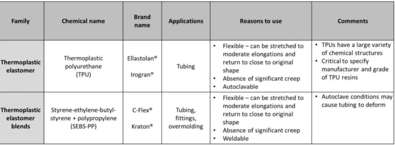
Table 7. Example of plastics used for tubing (Thermoplastic elastomer)... 32
Table 8. Example of plastic used for tubing (Copolymer) ... 32
Table 9. Examples of plastics used for tubing (Fluoropolymers) ... 32
Table 10. Different types of connectors ... 34
Table 11. Today´s Tube features ... 49
Table 12. Features of the today´s transfer tube material ... 49
Table 13. Combined thawing and transfer Tubes A, B and C features. ... 53
Table 14. Features of the tube materials used in the experiment ... 54
Table 15. Transfer speeds of Today´s Tube and Tube A, B and C ... 66
Table 16. Transferred amount/time of Today´s tube, Tube A, B and C ... 69
Table 17. Correspondence of the tubes for the statistical methods ... 70
Abbreviations
ADC - Antibody drug conjugate
ANOVA
-
Analysis of varianceAPI - Active Pharmaceutical Ingredient
ASTM - American Society for Testing and Materials Cfu – Colony forming units
cGMP – Current Good Manufacturing Practices CI – Confidence interval
CIP – Clean- in- place
FDA – Food and Drug Administration
HPAPI – Highly potent active pharmaceutical ingredients ID – Inner diameter
ISO – InternationalOrganization for Standardization Kg – Kilograms
kGy - Kilogray
LAL - Limulus amebocyte lysate Min - Minutes
OD – Outer diameter
OEB – Occupational exposure bands OEL – Occupational exposure limits QC – Quality Control
SIP – Sterilization- in- place
SOP – Standard operating procedures StDev – Standard deviation
Glossary
Active Pharmaceutical Ingredient - any substance or combination of substances used in a finished pharmaceutical product, intended to furnish pharmacological activity or to otherwise have direct effect in the diagnosis, cure, mitigation, treatment or prevention of disease, or to have direct effect in restoring, correcting or modifying physiological functions in human beings.
Aseptic - free of pathogenic microorganisms.
Batch - a quantity of any drug produced during a given cycle of manufacture.
Basic clean rooms – clean rooms that have control of airflow, air filtration, air velocity, air changes, air pressure, airborne particulates, temperature, humidity and microorganisms.
Bioburden - population of viable microorganisms on or in raw materials, products, and labeling/packaging materials determined before sterilization.
Clean in place - cleaning of equipment in its assembled condition and at its location. This cleaning may be an automatic process or manual. Whatever the method, it must comply with the stringent hygiene regulations of the pharmaceutical industries.
Clean room area - an area (or room or zone) with defined environmental control of particulate and microbial contamination, constructed and used in such a way as to reduce the introduction, generation and retention of contaminants within the area.
Containment - a process or device to contain product, dust or contaminants in one zone, preventing it from escaping to another zone.
Contamination - The undesired introduction of impurities of a chemical or microbiological nature, or of foreign matter, into or on to a starting material, intermediate or pharmaceutical product during handling, production, sampling, packaging or repackaging, storage or transportation.
number of particles per m3 equal to or greater than 0,5 µm is at rest 352000 and is in operation 3520000. The maximum permitted number of particles per m3 equal to or greater than 5 µm is at rest 2900 and is in operation 29000. The recommended limits for microbial contamination in contact plates (Ø 55mm) are 25 cfu/plate.
Cross contamination - contamination of a starting material, intermediate product or finished product with another starting material or product during production or due to microorganisms.
Current Good Manufacturing Practices – is the aspect of quality assurance that ensures that medicinal products are consistently produced and controlled to the quality standards appropriate to their intended use and as required by the product specification.
Class D - a clean area for carrying out less critical stages in the manufacture of sterile products. In this clean area personal must take hair cover, beard cover, a general protective suit and shoe covers. This area has a maximum permitted number of particles per m3 at rest and in operation and has recommended limits for microbial contamination. The maximum permitted number of particles per m3 equal to or greater than 0,5 µm is at rest 3520000 and is not defined in operation. The maximum permitted number of particles per m3 equal to or greater than 5 µm is at rest 29000 and is not defined in operation. The recommended limits for microbial contamination in contact plates (Ø 55mm) are 50 cfu/plate.
Endotoxin - lipopolysaccharide contained within the outer membrane of Gram-negative bacteria that may lead to pyrogenic reactions and other biological activities in humans. Gamma irradiation – the operation of exposing a material to gamma rays in order to sterilize.
Gray space – non-defined clean room area.
LAL test - used for the detection and quantification of bacterial endotoxins.
Process qualification - confirming that the manufacturing process as designed is capable of reproducible commercial manufacturing.
Good Manufacturing Practices. Process validation involves a series of activities taking place over the lifecycle of the product and process.
Qualification - action of proving and documenting that equipment or ancillary systems are properly installed, work correctly, and actually lead to the expected results. Qualification is part of validation, but the individual qualification steps alone do not constitute process validation.
Sanitization - process of decontamination that reduces viable microorganisms to a defined acceptance level.
Shelf life - The period of time during which a pharmaceutical product, if stored correctly, is expected to comply with the specification as determined by stability studies on a number of batches of the product. The shelf-life is used to establish the expiry date of each batch.
Spalling – is the removal of small particulate matter from the inner wall of flexible tubing when subjected to repeated deformation and flexing.
Standard operating procedures – an authorized, written procedure giving instructions for performing operations not necessarily specific to a given product but of a more general nature (e.g. equipment operation, maintenance and cleaning, validation, cleaning of premises and environmental control, sampling and inspection).
Sterile – complete absence of microorganisms.
Sterilization - complete destruction or removal of all microorganisms including spore-forming and non-spore-spore-forming bacteria, viruses, fungi, and protozoa.
Sterilization in place –sterilization of equipment in its assembled condition and at its location.
1.
Introduction
1.1. Disposable technologies
It has been about a decade since disposable products were introduced to the biomanufacturing industry. While disposables have been examined for years in less regulated environments, disposable manufacturers had to demonstrate their benefits and qualities to convince biomanufacturers to try them (Mintz, C. 2009; Whitford, W. G., 2010).
Pharmaceutical drug products should be produced with efficiency (reduced costs and less production time) and with high quality according to current Good Manufacturing Practices (cGMP) as shown in the iron triangle (see figure 1) (Valle, C., 2009; Sandle, T., & Saghee, M. R., 2011). Quality-Time-Cost is in the middle of the development process. At each verification point, choices have to be made, based on Quality-Time-Cost. There must be a balance between the three pillars of the triangle. For example too little time could lead to poor quality, which can prove very expensive later on. Therefore, ways have to be found to improve quality and still cut on time and costs (Legrand, B., 2004).
However, the presence of microbiological contamination can affect the quality and the efficiency leading to batch rejection. Therefore, an emphasis on risk reduction should be an essential component of sterile product manufacturing. A focus on high quality operating clean rooms, trained staff, the use of sterilized clean room items and recent technologies are examples of what can be done to support this goal (Sandle, T., & Saghee, M. R., 2011).
The development from basic clean rooms to novel clean roomtechnologies over the last years has resulted in a reduction on the risk of product contamination and in a
simplification of the process operation. These novel technologies include the following: barrier isolated systems and RABS (restricted access barrier systems) to protect the aseptic filling; methods to protect the product from personnel contamination such as particle reducing air showers; sanitization and sterilization methods to decontaminate clean rooms and sterile disposable technologies. The use of disposable technologies allowed pharmaceutical companies to substitute equipment that needs to be sterilised by disposable items (Sandle, T., & Saghee, M. R., 2011).
appropriate for different applications and should be evaluated for suitability (Repetto, R., et al., 2014).
1.1.1. Examples of disposable technologies
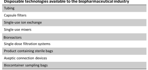
Table 1. Common types of disposable technologies used in the biopharmaceutical industry. Adapted from Sandle, T., & Saghee, M. R. (2011).T
When using a disposable unit, there are a number of factors that should be considered, such as the number of manufacturing campaigns per year, the size of the production unit (volume and capacity requirements), the operating conditions (pressure, temperature and operation period) and the compatibility of the product with the disposable unit (Aranha, H., 2004).
1.1.2. Disadvantages
and/or extractables can modify the safety, quality, identity, strength or purity of the drug products. Therefore, the FDA offers guidance for protection against leachables and extractables (Kauffman, J. S., 2006).
1.1.3. Advantages
The adoption of disposables has been increasing due to a variety of advantages over traditional stainless steel systems, which include: decreased risk of cross-contamination, increased assurance of sterility, safety considerations, process efficiencies, cost saving and others (Aranha, H., 2004, Mintz, C. 2009; Sandle, T., & Saghee, M. R., 2011). Cross-contamination
Cross contamination might result from microbiological contamination that can be transferred from one batch to another, and from product adulteration, which means that chemical residues can also be transferred from one batch to another. Disposables decrease the risk of cross-contamination because they are single used and consequently not used for further operations (Sandle, T., & Saghee, M. R., 2011).
Sterility assurance
The assurance of sterility is achieved due to a reduction of cross-transference of microorganisms that diminishes the risk of environmental microbial contamination and also due to a reduction of inadequate sterilisation cycles. The use of disposables avoid cross contamination since the need to clean components disappears, thus reducing manual handling. In addition, it allows the pharmaceutical companies to distance themselves from equipment that needs to be sterilized or offer a risk with their transfer to clean rooms. A reduction of microbial contamination is also achieved since structural integrity tests (testing for leaks) of disposable technologies are also made by the manufacturers and by the pharmaceutical company (Sandle, T., & Saghee, M. R., 2011; Jenness, E., & Gupta, V., 2011; Repetto, R., et al., 2014).
Safety considerations
manipulates cytotoxic drugs, so called highly potent drugs or radiolabeled chemicals. The handling of the operator with hazardous active pharmaceutical ingredients (API) is diminished because single use systems don’t need clean in place (CIP) and sterilization in place (SIP) operations. Thus, disposable systems protect the operator from materials that can compromise his health and are in the best interest of manufacturing personnel (Aranha, H., 2004; Sandle, T., & Saghee, M. R., 2011).
Process efficiencies
The use of disposables has advantages with regard to process efficiencies in comparison with reusable stainless steel systems. Reusable stainless steel systems lead to equipment support and routine inspections that need labour, time, effort and money. With the use of disposables labour and time can be saved by decreasing operator dependence so that operators and other resources can be used for other tasks. Disposables also reduce process downtime and eliminate CIP and SIP, which save time, energy and costs. Time is also saved because qualification and validation are facilitated (Aranha, H., 2004; Eibl, D., Peuker, T., & Eibl, R., 2011). Moreover they save waste disposal and quantities of detergents and other cleaning chemicals that are used. The most important advantage is faster turnaround times. There is a reduction of the time taken to obtain a new batch ready for processing (Aranha, H., 2004; Mintz, C. 2009; Sandle, T., & Saghee, M. R., 2011). Costs savings
Therefore, the use of disposable technologies not only increases quality since these technologies decrease cross contamination, assure sterility and are safer but also reduces costs and time.
1.1.4. Qualification and Validation
GMP regulations that are involved with the production of drugs and active pharmaceutical ingredients (API´s) are supported by the FDA regulations 21 CFR Parts 210 and 211 and internationally they are supported by the European Union directive 356 (Day, N., 2004). Disposable technologies are manufactured according to cGMP, and must be qualified and validated to guarantee that the equipment is not reactive, additive or absorptive, which is important to assure that the safety, identity, strength, quality or purity of the API is not affected(CFR, 2014).
Disposable technologies are manufactured with pharmaceutical grade polymeric materials that are tested to meet the requirements of USP<87>, USP<88>, USP<661> ISO 10993 and EP <3.1.9> (Creasey, J. & Thibion, V., 2013; Mueller, D., 2014). The qualification and validation methods have to demonstrate that the disposable is reliable, robust and safe (Belongia, B. M., & Allay, J. A., 2006).
Single use systems are sterilized with gamma irradiation, which can decrease the shelf life of disposables and can accelerate the degradation of the polymeric substances. Qualification tests must be done to determine the effects of irradiation and the stability of the polymer used. Some qualification tests are (Aranha, H., 2004; Jornitz, M. W., Cappia, J.-M. & Meltzer, T. H., 2009; Jornitz, M. W., Szarafinski, D., & Peuker, T., 2012; Mueller, D., 2014):
Biocompatibility testing:
o USP ‹87› biological reactivity tests, in vitro,
o USP ‹88› biological reactivity tests, in vivo.
Mechanical properties:
o tensile strength, o elongation at break, o seal strength, o air leak test.
Gas transmission properties:
o ASTM F1249: water vapour.
USP ‹661› test for plastics.
European Pharmacopeia (EP) <3.1.7.>: Ethylene vinyl acetate (EVA) for containers and tubing.
European Pharmacopeia (EP) <3.1.9.>: Silicone elastomers for closures and tubing. European Pharmacopeia (EP) <5.2.8.>: Minimizing the risk of transmitting animal
spongiform encephalopathy agents via human and veterinary medicinal products. Total organic carbon (TOC) analysis.
pH and conductivity.
Extractable and leachable tests with standard solutions. Chemical compatibility testing.
Protein adsorption studies. Endotoxin testing.
Gamma irradiation sterilization validation. Bacterial ingress test.
These tests are performed by the disposable technologies manufacturer under standard setting and solutions, so they only serve as guidance for the pharmaceutical company that buys the disposable technologies. Thus, before implementing the disposable technologies in the manufacturing process, the system users must validate them under specific requirements and process conditions (Aranha, H., 2004; Jornitz, M. W., Cappia, J.-M. & Meltzer, T. H., 2009; Jornitz, M. W., Szarafinski, D., & Peuker, T., 2012).
1.1.5. Environmental impact
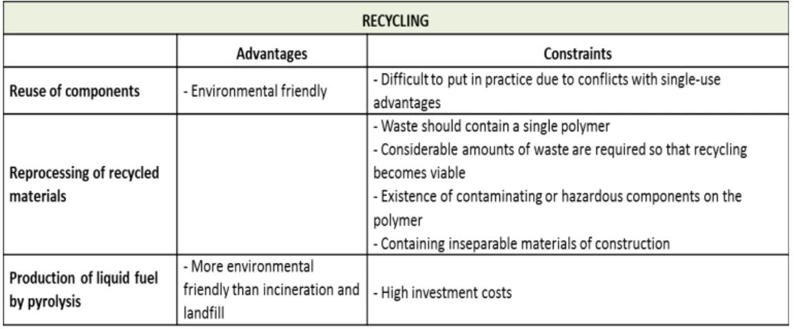
Table 2. Recycling advantages and constraints. Adapted from Pora, H., & Rawlings, B. (2009). The environmental impact of disposable technologies has become a concern in recent years (Rawlings, B., & Pora, H., 2009; Pora, H., & Rawlings, B., 2009). Thus, manufacturers should choose recyclable materials of construction for disposable systems instead of using materials made from non-renewable feedstocks (Rao, G., Moreira, A., & Brorson, K., 2009). Disposable systems should be designed and manufactured to ensure a minimum environmental impact and a maximum recyclability of waste (Rao, G., Moreira, A., & Brorson, K., 2009; Pora, H., & Rawlings, B., 2009).
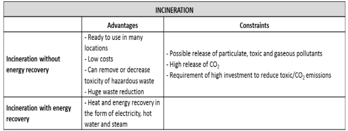
Another concern is the environmental impact of currently used disposal methods, which should consider the legislation in force to protect the environment and guarantee industrial sustainability. There are three major solid-waste disposal methods for disposable systems: 1) recycling options, which include the reuse of components, the reprocessing of recycled material and the production of liquid fuel; 2) incineration, with or without energy recovery; 3) landfills (non-hazardous waste, hazardous waste). The following tables summarize the advantages and constraints of the methods above mentioned (Pora, H., & Rawlings, B., 2009):
Table 4. Landfill advantages and constraints. Adapted from Pora, H., & Rawlings, B. (2009). Table 3. Incineration advantages and constraints. Adapted from Pora, H., & Rawlings, B. (2009).
Figure 2. Decision tree for management of solid waste (Pora, H., & Rawlings, B., 2009).
1.2. Highly potent drugs
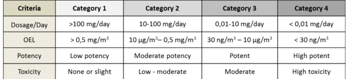
joined to the HPAPI by a short linker molecule, which is designed to break down at the active site and release the cytotoxic (Bormett, D., 2008; Lonza, 2012; Wooge, C., 2014) Every API must be evaluated and classified to assess potential toxicity, potency and potential hazards so that the level of containment that is required can be determined (Bormett, D., 2008). The drug substances can be classified according to their potency based on the use of occupational exposure limits (OEL) or occupational exposure bands (OEB) (Calkins, T., 2010; Wollowitz, S., 2010; Harris, R., 2012). The OEL is given in microgram (µg) per cubic meter (m3) or milligram (mg) per cubic meter (m3) and as the most likely and toxic route is by inhalation it is defined as the air concentration of the compound that can be inhaled by a worker over an 8h working day, 40 hours a week without adverse effects (Wollowitz, S., 2010; Denk, R., 2014). A lower value of OEL means a more potent compound which requires a higher level of containment (Van Arnum, P., 2009). The OEB group together substances by an approximate hazard level and this dictate the handling containment required to work with the substances (Wollowitz, S., 2010; Bowman, M., 2013). In the last years, a number of systems have been proposed to classify APIs (Harris, R., 2012). The industry uses different category systems ranging from three to six - category systems (Farris, J. P., Ader, A. W., & Ku, R. H., 2006; Calkins, T., 2010). There are also companies that developed their own category system, according to their equipment and facilities (Bowman, M., 2013). There are different category systems because companies have different products, facilities, equipment and processes (Farris, J. P., Ader, A. W., & Ku, R. H., 2006). The system that is more frequently used is the four category system, the SafeBridge System and its evaluation and categorisation are described in table 5 (Farris, J. P., Ader, A. W., & Ku, R. H., 2006; Harris, R., 2012; Bowman, M., 2013).
1. The active pharmaceutical ingredient has an OEL of ≤ 10 µg/m3 of air as an 8 hour time weighted average.
2. The active pharmaceutical ingredient has a therapeutic dose of ≤ 10 mg/day. 3. The dose of 1 mg/kg/day of active pharmaceutical ingredient produce serious
toxicity in laboratory animals.
4. The active pharmaceutical ingredient has high selectivity and/or has the potential to cause cancer, mutations, developmental effects or reproductive toxicity at low doses.
5. It is a novel compound of unknown toxicity.
The handling with highly potent active pharmaceutical ingredients requires a substantial investment in specialized containment to guarantee that workers and the working environment are protected from exposure (Bormett, D., 2008). A safe handling with highly potent active pharmaceutical ingredients can be achieved by using standard operating procedures (SOPs), trained workers, containment equipments, personal protective equipment, process isolation, facility design and cGMP activities (Bormett, D., 2008; Karmarkar, A. B., 2012).
1.2.1. Facility design
Handling with highly potent active pharmaceutical ingredients requires specialized equipment to achieve containment and attention to safety. A facility should be designed with equipment such as isolators with laminar flow hoods and appropriate ventilation for potent compound handling to protect workers and to maintain the product sterile. The room pressure should be negative to its surrounding rooms to guarantee that the potent products are retained in the working environment. The air should also be filtrated so that escaping product is captured before its release to the external environment. To prevent cross contamination or concentration of materials, the airflow in the facility must be single pass. Process isolation and containment equipment are very important to ensure that an entire manufacturing process is carried out in closed systems (from raw materials to product packaging) so that the chances of operators exposure can be minimized (Van Arnum, P., 2009; Calkins, T., 2010; Wooge, C., 2014).
contamination. Therefore, the handling steps involving HPAPI should take place in an isolator in a separate room, where the air is under negative pressure. HPAPIs can only leave this room if they are in solution, because this removes the risk of airborne contamination and the chances of operators or environment contamination are much lower. The conjugation to an antibody occurs in a second room which is under positive pressure and therefore protects the product from external contamination. The conjugation reaction must still take place in a closed system that enables full containment of hazardous materials, because despite being in solution HPAPIs are still hazardous (Calkins, T., 2010; Wooge, C., 2014).
Disposable technologies are a suitable option for handling with HPAPIs as they can improve containment. They protect and reduce the exposure of the operators from the compounds, they eliminate the need for extensive cleaning that potent drugs require and decrease cross contamination. The adoption of disposable technologies is of extreme importance in order to avoid the present risk of contamination of HPAPI in multiproduct facilities (Greb, E., 2010; Challener, C., 2014).
1.3. Cryo-vessel
Cryo-vessels are large-scale cryo-preservation systems made of stainless steel containers from 50-300 L. They are divided in two compartments. The inner compartment contains the API solution, whereas the outer compartment, named double coat is for the circulation of silicon oil. They are systematically frozen and thawed with a well-controlled heat or cold transfer fluid (silicon oil) that circulates in the outer compartment and goes in the internal compartment through an inner tube snake with fins, which efficiently transfer heat or cold into the solution (Arnitz, T., & Liebig, C., 2011; Kantor, A., MacMillan, S., Ho, K., Tchessalov, S., & Warne, N., 2011; Kolhe, P., & Badkar, A., 2013).
As proteins lack stability when in solution, it was considered convenient since a long time, to freeze them because of the need to store proteins for a large period of time. New approaches to the freezing and storage of proteins have been developed in which the freeze-thaw process is better controlled due to the emergence of large scale production of proteins (Kantor, A., Tchessalov, S., & Warne, N., 2011).
Protein based API can be stored under a variety of conditions such as refrigerated liquids and spray dried powders. However, a considerable number of clinical and commercial API are stored in a frozen state (Kantor, A., Tchessalov, S., & Warne, N., 2011).
There are three types of container closure system normally used for frozen API: plastic or stainless steel bottles between 1-5 L, plastic bags between 1-16 L and stainless steel cryo-vessels between 50-300 L. Although there has been a development of the systems, there is still a need for all these three systems depending on the nature of the drug substance, its volume and storage temperature (Kantor, A., Tchessalov, S., & Warne, N., 2011; Kolhe, P., & Badkar, A., 2013).
1.4. Tubings and Connectors
Nowadays the economic situation is an obstacle for the development of new drugs. As a challenge, the pharmaceutical companies have to review their manufacturing systems and find ways to make them more reliable, flexible and cost-effective. Therefore traditional stainless steel equipment has been replaced by pre-sterilized disposable technologies (Boehm, J., 2010).
1.4.1. Tubings
Flexible tubings have gained more acceptance in recent years due to its low costs associated with validation, CIP and SIP (Spontak, R. J., & Patel, N. P., 2000; Colas, A., Malczewski, R., & Ulman, K., 2004).
Silicone can have diverse applications: as excipients in topical formulation, as excipients in controlled devices and in pharmaceutical manufacturing for siliconisation, as antifoam and for tubing. Silicone tubings are used in pharmaceutical manufacuturing operations for transfer processes. Two types of silicone tubings may be used: platinum-cured silicone tubings or peroxide-cured silicone tubings. It is preferable to use platinum-cured silicone tubings since it is naturally purer and it offer fewer leachables and extractables; they have smoother internal surfaces and it minimizes protein loss due to adhesion. Moreover peroxide cured tubings contain peroxide by-products that can be released and contaminate the transferred product (Colas, A., 2001, Aranha, H., 2004; AdvantaPure, 2013). The platinum-cured silicone tubings can have different applications such as in ultra-pure fluid transfer or in peristaltic pumps, where durability is required or in high/low pressure applications (Dow Corning).
Tubings that can be heat sealed and welded are often needed at some point in the fluid path. Instead of using multiple materials in the different sections of the fluid path since not all materials have the required characteristics (for example: heat sealed and welded capacity), a material that meets the needed requirements of the customer can be selected. Tubing materials such as thermoplastic elastomer (combine the material properties of rubbers and plastics) meet the conditions that are often required.This kind of tubing is flexible, has a high purity, is less permeable and is a peristaltic pump tubing that may be welded and sealed, thus eliminating the use of multiple materials in a fluid path (AdvantaPure, 2013). Thermoplastic elastomer can be divided in two groups: multiblock copolymers which consist of soft elastomers and hard thermoplastic blocks such as thermoplastic polyurethane and blends (Shanks, R., & Kong, I., 2012).
Other plastics that can be used for tubing:
Table 7. Example of plastics used for tubing (Thermoplastic elastomer). Adapted from Repetto, R., et al. (2014).
In the cGMP environment flexible tubing has to be qualified and validated. So, the tubing that are considered for single use application as well as for multiple use application need to meet FDA, ISO, USP, EP and ASTM standards. In case of an inspection in the US it is sufficient that the tubing meet the US standards and in case of an inspection in the Europe it is sufficient that the tubing meet the Euopean standards. Therefore, according to the country where it is manufactured and according to the delivery country the following standards should be fulfilled (Colas, A., Malczewski, R., & Ulman, K., 2004; Hunt, D. G., 2013; Mueller, D., 2014):
US standards:
FDA G95-1 Memorandum: Required Biocompatibility Training and Toxicology Profiles for Evaluation of Medical Devices.
FDA 21 CFR 177.2600: Rubber articles intended for repeated use. USP <85>: Bacterial Endotoxins Test.
USP <87>: Biological Reactivity Tests, In Vitro.
USP <88>: Biological Reactivity Tests, In Vivo, Classification of Plastics: Class V and VI.
USP <1663>: Extractables. USP <1664>: Leachables.
ASTM F748-98: Standard Practice for Selecting Generic Biological Test Methods for Materials and Devices.
International standards:
ISO 10993: Biological Evaluation of Medical Devices, Part 1: Evaluation and Testing. ISO 10993: Biological Evaluation of Medical Devices, Part 5: Tests for in vitro
cytotoxicity.
ISO 10993: Biological Evaluation of Medical Devices, Part 11: Tests for systemic toxicity.
European standards:
ASTM F748-98: Standard Practice for Selecting Generic Biological Test Methods for Materials and Devices.
1.4.2. Connectors
Many of the advantages of disposable technologies would be lost if manufactures could not safely connect systems to create an aseptic process, once a connector can be the determining factor in keeping a process strictly aseptic (Boehm, J., 2010).
The risk of contamination requires special attention in biopharmaceutical processes since almost every biopharmaceutical process implicates making sterile connections between fluid pathways. Traditionally, reusable fittings have been used, particularly those made of stainless steel (e.g. a stainless steel tri-clamp), but the tendency is towards the use of disposable connectors (Mach, C. J., & Riedman, D., 2008).
A wide variety of connectors are commercially available and the right choice depends on the needs and preferences of a given facility and customer (Boehm, J., 2010).
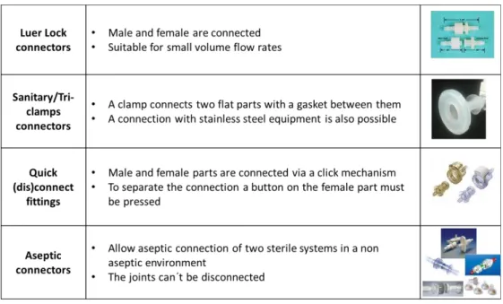
The different types of connectors are summarized in the table below (Rothe, S. & Eibl D., 2011; Niazi, S. K., 2012; Shukla, A., Mostafa, S., Wilson, M., & Lange, D., 2012):
There are different systems for aseptic connection:
1. Connection under laminar flow hood or in a clean room area class A:
Luer-lock connectors, tri-clamps and quick (dis)connect connectors provide fast and easy connections and should be used together with laminar flow hood. Careful handling with this type of connectors is needed to prevent contamination. Examples of this kind of connectors are: tri-clamps and MPC® Series from Colder Company (Boehm, J., 2010; Rothe, S. & Eibl D., 2011).
2. Sterilisation in place connectors:
These types of connectors create sterile connections between a range of disposable systems and stainless steel equipment. They can be sterilized at the point of connection. Examples of this kind of connectors are: Steam-Thru System® from Colder Company and Lynx ST® from Millipore Company (Boehm, J., 2010; Rothe, S. & Eibl D., 2011).
3. Aseptic connectors
Aseptic connectors allow aseptic connection without laminar flow hood like conventional connectors. These connectors are secure, the connections can be achieved rapidly without any further support or additional equipment and permit a sterile fluid pathway in a
non-Figure 4. Quick-connectors: MPC® Series from Colder Company
Figure 6. Lynx ST® from Millipore Company
a) b)
Figure 3. Triclamp disposable (a) and a stainless steel clamp (b)
aseptic environment (gray space). The aseptic parts on the connector side are sealed with sterile membrane filters or caps. After coupling, the sterile membrane filters or caps must be removed and both parts have to be clamped or fixed. The connection is then ready for use. It is not possible to disconnect connectors that are once connected. Examples of this kind of connectors are: Kleenpak KPC® by Pall, Lynx S2S® by Millipore, Opta SFT-1® by Sartorius Stedim Biotech, ReadyMate DAC® by GE and the Pure-Fit SC® by Saint-Gobain (Strahlendorf, K. A., & Harper, K., 2009; Boehm, J., 2010; Rothe, S. & Eibl D., 2011).
The variety of plastics and connectors enables the development of innovative equipment and provides customization.
Figure 9. Opta SFT-1® by Sartorius
Stedim Biotech
Figure 11. Pure-Fit SC® by
Saint-Gobain
Figure 8. Lynx S2S® by Millipore
Figure 10. ReadyMate DAC® by
GE
1.5. Fluid transfer
In the manufacturing process the fluid can be transferred either by pump systems or by pressurizing (Kubischik, J. & Schaupp, M., 2011).
1.5.1. Pump systems
Pumps can be classified in two types: positive displacement pumps and rotodynamic pumps. Both types are designed to transfer fluids but the way this is accomplished differs (Srinivasan, K. M., 2008).
A positive displacement pump moves the same amount of fluid for each rotating cycle of the system. It uses mechanisms that seals fluid in a chamber and forces it out by reducing the volume of the chamber. This action increases the fluid pressure. The motion can be rotary or reciprocating (Srinivasan, K. M., 2008; Gupta, A. K. & Arora, S. K., 2013). In a rotodynamic pump there is a free passage of fluid between the inlet and outlet of the machine without sealing. Rotodynamic pumps have a rotating part called impeller, which rotates the fluid continuously and transfers energy from the rotor to the fluid (Garde, R. J., 1997; Gupta, A. K. & Arora, S. K., 2013).
Piston pumps have been a traditional technology in pharmaceutical technology. However due to stricter validation requirements and design innovations peristaltic pumps started to be considered instead of piston pumps (Lambert, P., (2008).
Piston pump
A piston pump is a positive displacement pump. It is a mechanical device that cycles through a suction phase and a pressure phase to move fluid. Internal parts of a piston pump (gaskets, seals, valves and internal surfaces) are in direct contact with the fluid. Piston pumps are known for their reliability and accuracy. However, they require regular maintenance and disassembly for cleaning and sterilization and cross contamination between batches is a concern. In addition, they also apply high pressure and high shear forces, that are inappropriate for biological drugs which are shear sensitive (Lambert, P., 2008).
Peristaltic pump
A peristaltic pump is also a positive displacement pump. In this pump type the fluid is moved forward by progressively squeezing and releasing the flexible tubing (Avis, K. E. (Ed.) 1995; Lipták, B. G. (Ed), 2003; Volk, M., 2014). The product only comes in contact with the flexible tubing. For this reason peristaltic pumps can be used for single aseptic processes (Lambert, P., 2008).
Peristaltic pumps using disposable tubes eliminate the possibility of cross contamination and the cleaning of the pump isn't required since the tubing is the only part that comes into contact with the fluid (Lipták, B. G. (Ed), 2003; Niazi, S. K., 2012). It also can be used with some biological drugs that are shear sensitive, since they apply low pressure and provide a gentle handling (Niazi, S. K., 2012). However, studies have shown that some tubing materials release particles (spalling) during the use with peristaltic pumps, due to their poor abrasion resistance and consequently, contaminating the solution (Bahal, S. M., & Romansky, J. M., 2002; Colas, A., Malczewski, R., & Ulman, K., 2004). 1.5.2. Pressurizing
1.6. Influence of Pump systems and Pressurizing in protein solutions
In some cases, during manufacturing, proteins undergo a variety of stresses leading to physical and chemical instability that can compromise the quality, safety and efficiency of the proteins, such as monoclonal antibodies and the yield of the final drug product. Physical instability causes changes in the higher order structure of proteins (secondary, tertiary or quaternary structure), which include denaturation, aggregation, precipitation or adsorption to surfaces. Chemical instability is a covalent modification of the protein via bond formation or cleavage (Banga, A. K., 2005; Bausch, U. J., 2008; Vázquez-Rey, M., & Lang, D. A., 2011; Ma, J. K., & Hadzija, B., 2013).
Protein aggregation can be induced by various processing steps during manufacture such as pumping and pressurization (Vázquez-Rey, M., & Lang, D. A., 2011).
Pumping processes expose proteins to mechanical shear forces that can cause protein aggregation and formation of particles. However, the extent of impact depends on the intensity and on the duration of exposure to such stress. Shearing creates a hydrophobic air/water interface which results in the alignment of protein molecules at the interface. The alignment of the protein molecules at the interface occurs since proteins denature exposing the hydrophobic residues to the air, forming unfolded intermediates that induce protein aggregation (Wang, W., 1999; Vázquez-Rey, M., & Lang, D. A., 2011; Ma, J. K., & Hadzija, B., 2013). To reduce shearing-induced protein aggregation, surfactants can be used as they compete with the protein molecules for the hydrophobic interfaces by binding directly to proteins or by increasing the viscosity of a protein solution limiting the movement of proteins (Wang, W., Nema, S., & Teagarden, D., 2010). Certain pumps like piston pumps and peristaltic pumps can form protein particles (for example white tornadoes) due to shear. However, peristaltic pumps generate less protein particles as piston pumps (Bausch, U. J., 2008; Roche Internal Report, 2008; Nayak, A., Colandene, J., Bradford, V., & Perkins, M., 2011).
The formation of aggregates due to pumping can also be minimized using pressure for the transfer of fluids (Vázquez-Rey, M., & Lang, D. A., 2011).
2.
Target
The purpose of this master thesis is to test the possibility to transfer API solutions with peristaltic pump and overpressure in combination with a combined thawing and transfer disposable tube and to verify if it is advantageous to replace the current thawing and transfer disposable tubes used in the API thawing and drug product compounding process by a new combined thawing and transfer disposable tube in order to diminish the quality risks of manual handling, reduce assembling time and improve safety of ADCs.
3.
Types of Cryo-vessels
Roche Diagnostics GmbH, Mannheim operates with three different types of cryo-vessels, namely US (United States Cryo-vessel), Basel and Penzberger (European Cryo-vessels).
3.1. US Cryo-vessel Type
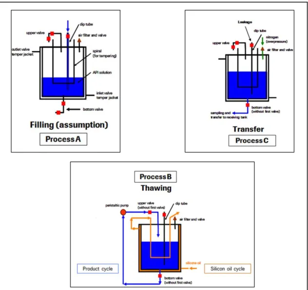
The product filling process (Process A) is the same regardless of what type of cryo-vessel is utilized. The filling of API solution is done by a dip tube, which extends from the top of the cryo-vessel to the bottom, allowing the filling of the inner compartment. After the filling process is completed, the cryo-vessel can be transported and stored.
The thawing process is divided in two cycles: silicon oil and product cycle (Process B). Silicon oil cycle: the silicon oil circulates in the outer compartment of the cryo-vessel, named double coat and in the inner tube snake. The circulation of the silicon oil in the cryo-vessel warms the API solution allowing its thawing.
Product cycle: it is used a thawing disposable tube, that is connected on the bottom valve and on the upper valve and passes through a peristaltic pump, that pumps the API solution for its homogenization and for heat distribution during thawing. The API circulation starts always from the bottom valve to the upper valve, where it enters in the inner compartment. The transfer of the API solution (Process C) is made through a transfer disposable tube that is connected to the bottom valve and to the receiving tank in the compounding room. The transfer process is done through overpressure with nitrogen, where the nitrogen has to pass through a 0,22 µm filter in the cryo-vessel to ensure sterility (figure 13, Process C).
(a)
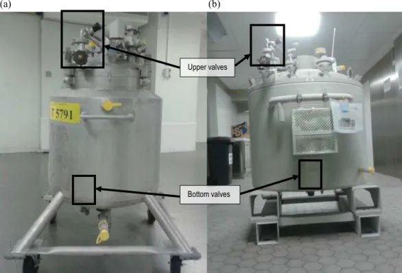
Figure 14. US Cryo-vessel type of (a) 120 L and (b) 300 L, with upper and bottom valves highlighted.
(b)
3.2. Basel and Penzberger Cryo-vessel Types
The Basel and Penzberger Cryo-vessel types only exist with the capacity of 300 L. They differ from each other in the localization of the upper valve and the dip tube.
The differences between US Cryo-vessel type and Basel and Penzberger Cryo-vessel types are in the thawing process (Process B), in the product cycle and in the transfer process (Process C).
Product cycle (Process B): the thawing disposable tube is connected on the dip tube from where the API solution leaves, passes through a peristaltic pump, and on the upper valve where the API solution enters to the inner compartment.
The transfer of the API solution (Process C) is made through a transfer disposable tube that is connected to the dip tube and to the receiving tank in the compounding room. With the Basel and Penzberger Cryo-vessel types the transfer process is also done through
a)
b)
Figure 16. Penzberger Cryo-vessel type of 300 L (left) and close-up showing of the upper valve (a) and of the dip tube (b)
Figure 17. Basel Cryo-vessel type of 300 L (left) and close-up showing of the upper valve (a) and of the dip tube (b)
a)
4.
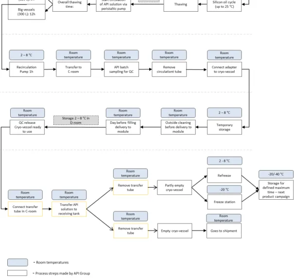
Today’s Cryo-vessel process cycle (API), Roche Mannheim
5.
Today’s API thawing and transfer process
Before starting the thawing process the thawing disposable tube must be attached to the cryo-vessel in a class C room. The thawing disposable tube length is approximately 4 meters (m) and must be cut with a sterilized scissor in two parts, one with the length of approximately 3 m and the other with the length of approximately 1 m. Linked to the thawing tube is a Nova Septum® bag for bioburden sampling and a syringe used for endotoxins (LAL test) sampling. The polyethylene Nova Septum® bag was validated for bioburden and the polycarbonate syringe was validated for endotoxins (Roche Internal Document, 2010).
In a 2-8 °C room the thawing tube is connected to a peristaltic pump, which will allow the thawing process, product cycle.
Figure 19. Today’s thawing tube (a) attached with a Nova Septum® and a syringe for sampling (b)
(a) (b)
(b)
Figure 20. Upper valve of US Cryo-vessel (a) and connection of the thawing disposable tube with the upper valve before the thawing process (b)
Subsequently, begins the silicon oil cycle. The silicon oil circulates in the outer compartment of the cryo-vessel, named double coat and in the inner tube snake, heating the API solution.
(a) (b)
Table 12. Features of the today’s transfer tube material. Adapted from AdvantaPure (2012).
Table 11. Today’s Tube features
After four hours of heating starts the product circulation via peristaltic pump. The thawing process takes 9 hours in case of a small cryo-vessel (120 L) and 12 hours in case of a big cryo-vessel (300 L).
During the thawing process the operators and a machine document the thawing parameters (GMP-batch record). After the thawing process the cryo-vessel is cleaned outside and transported to a C-room. There, the operators take samples for microbiological Quality Control (QC) analysis of bioburden (Nova Septum® bag) and endotoxins, due to a LAL test (syringe) and take a sample for chemical QC analysis of identity of the API solution. The batch record, the analysis of bioburden and endotoxins and the analysis of identity will be reviewed by the QC. After that, the QC makes the decision to release, reject or quarantine the cryo-vessel in accordance with the quality.
Figure 23. Peristaltic pump for product circulation and the today´s thawing disposable tube in the peristaltic pump for product circulation
Figure 22. The silicon oil cycle. (a) Entry of silicon oil in the cryo-vessel; (b) Circulation of silicon oil in the double coat and in the inner tube snake in the cryo-vessel; (c) Exit of silicon oil out of the cryo-vessel
Subsequently they remove the thawing disposable tube and connect an adapter on the bottom valve in case of a US cryo-vessel. Before the implementation of an adapter, the operators in the compounding room had to lie down on the floor to connect the transfer tube with the compounding tank which increased the contamination risks. Therefore, the implementation of an adapter on the bottom valve aims to avoid having to lie down on the floor to connect the transfer tube from the cryo-vessel to the compounding tank. Consequently the adapter enables a safer connection between the cryo-vessel and the compounding tank and prevents operators from lying down on the floor minimizing the contamination risks.
Figure 24. Operators lying on the floor to connect the transfer tube before implementation of the adapter
When the QC decides that the microbiological and chemical samples and that the batch record meet the specifications, the cryo-vessel can be released.
In the compounding room, before connecting the transfer disposable tube from the cryo-vessel to the compounding tank the operators must to do a quick LAL test (Diagnostic Kit) for some products to check the microbiological quality after holding time (approximately two weeks). Sometimes it is necessary to use more than one cryo-vessel for the compounding. Therefore, the LAL test is made to prevent financial risks due to the possibility of the mixture of one API solution with suboptimal quality from one cryo-vessel with one with optimal quality from another cryo-cryo-vessel. If the result of the quick LAL test is negative they can connect the transfer disposable tube to the adapter in the cryo-vessel to and to the compounding tank and start the transfer process. The API solution is transferred trough overpressure to the compounding tank.
With this master work a first data base will be created for the decision if Roche Diagnostics GmbH, Mannheim can adopt a combined thawing and transfer disposable tube to reduce the operators manipulation and the assembly time. Moreover, with the implementation of a combined thawing and transfer disposable tube the operators will no longer need to connect an adapter on the bottom valve.Additionally it can be used with highly potent drugs (ADCs).
6.
Materials and Methods
The possibility of transferring product with a peristaltic pump and with overpressure in combination with a combined thawing and transfer disposable tube was tested and the most suitable method verified. Additionally, the transfer speed (kg/min) of three different combined thawing and transfer disposable tubes (Tube A, B and C) was measured using both transfer fluid methods, peristaltic pump and overpressure, and compared with the transfer speed of today´s transfer with overpressure of Product A, taking also into account other additional factors as presented in the tables 11 and 13.
Tube A is the only combined thawing and transfer disposable tube that is already qualified according to the cGMP.
Tube B and C were specially designed for Roche Diagnostics GmbH, Mannheim.
The experiments were performed on the pharmaceutical GMP equipment of Roche Diagnostics GmbH, Mannheim in the compounding room of Module 1 (pharmaceutical sterile drug product manufacturing process). The experiments were not performed under GMP conditions; for that reason the combined thawing and transfer disposable tubes were connected in a class D room.
Since Roche Diagnostics GmbH, Mannheim only works in a GMP environment the use of all types of vessels that were explained was not possible. In order to use a cryo-vessel for experiments, cleaning validation is needed due to possible API residues. The only cryo-vessel that was available to make the experiments was a US Cryo-vessel type (300 L), as it is a GMP training test vessel.
Figure 28. Peristaltic pump (up) and manometer and overpressure tube (right) used in the experiment
The solution that was used for testing was water for injection (WFI). For each designed experiment with the exception of the experiment with Tube C (pressure) the cryo-vessel was filled four times with WFI to obtain a final amount of 1031 kg of transfer solution. For the experiment with Tube C with pressure the cryo-vessel was filled three times with WFI to obtain a final amount of 1031 kg of transfer solution.
Amount of transfer product
The maximum volume that can be transferred to the compounding tank is approximately 1050 L. The compounding tank measures the transfer product in kg. So when the transfer product is WFI and 1000 L of WFI should be transferred, the final amount in the compounding tank is 1000 kg since the density of water is approximately 1g/cm3.
� � � ⁄ = �� = �� =�� � ⇔
⇔ � = � � � ⁄ x � � ⇔
Figure 29. US Cryo-vessel (300 L) used in the experiment
However Product A, which is used for the comparing of the transfer process, has a density of approximately 1,031g/cm3 which means that the final amount of transferred product in the compounding tank is 1031 kg.
� = � � � ⁄ x � � ⇔
⇔ � = , 3 x = 3
Since the final amount of the transferred product of Product A is 1031 kg it was transferred 1031 kg of WFI so that a comparison of the transfer speeds is possible.
6.1. Experiment
6.1.1. Tube A.
The first combined thawing and transfer disposable tube that was tested was Tube A. This tube is only suitable for the use of non-highly potent drugs and consists of three parts. Part A and B are intended to connect to the cryo-vessel for the thawing process and Part C combined with a Lynx S2S® connector is intended to connect to the compounding tank for the transfer process. Coupled to Part A are Nova Septum® bags that serve for batch sampling (Part D) (see figure 31).
Part C with Lynx
S2S
Part D
Figure 31. First disposable tube that was tested - Tube A. Part A is intended to connect with the upper valve, part B is intended to connect with the bottom valve, part C is intended to connect with the compounding tank and part D is intended to take samples
Part A Part B Part D
Part C with
Tube A was connected to the cryo-vessel in a class D room and then transported to the compounding room, class C room. Part A was connected to the upper valve of the cryo-vessel with a metal clamp and part B was connected to the bottom valve of the cryo-cryo-vessel also with a metal clamp.
Two methods were used as moving force for the transfer of the solution to the compounding tank: peristaltic pump and overpressure.
Experiment with peristaltic pump:
Although Part C has a Lynx S2S® connector, the experiment wasn´t performed with it as it was designed for another plant and didn´t fit for Module 1 processes. Therefore, the operators cut the connector and connected a short tube with a tri-clamp connection to the existing tube. In the compounding room the transfer tube (Part C) was connected to the compounding tank passing through a peristaltic pump with a tube connection piece. For the transfer process approximately 200 rpm were used.
Figure 32. US Cryo-vessel with Tube A in class D room
(a) (b)
Experiment with overpressure:
In the compounding room the transfer tube without Lynx S2S® connector (Part C) was connected to the compounding tank with a tube connection piece. Afterwards, the overpressure tube (nitrogen) was connected to the cryo-vessel. For the transfer process approximately 0,5 bar was used. Before nitrogen enters into the cryo-vessel it has to pass a 0,22 µm filter to ensure sterility.
Figure 34. Part C of Tube A passing through the peristaltic pump
(a)
(b)
(c)
Experiment design of Tube A with peristaltic pump and overpressure:
6.1.2. Tube B.
The second tube that was tested was Tube B. This tube is a delivery tube for the connection of different cryo-vessels (y-connector). It can connect up to four different cryo-vessels (Part B, C, D and E) and can be used for the handling of API solutions and for highly potent drugs, ADCs. Part A is intended for the connection with the compounding tank and Part F is intended for flushing in case of highly potent drugs, ADCs manipulation allowing the cleaning of the tube. However, Tube B was tested as a combined thawing and transfer disposable tube to test the silicon tube material (see figure 37).
Part C
Part D Part E
Part B
Part A
Part F
Figure 37. Second disposable tube that was tested - Tube B. Part A is intended to connect with the compounding tank, Part B, C, D, E are intended to connect with different cryo-vessels and part F is intended for flushing
Figure 36. Experiment design of Tube A (a) with peristaltic pump and (b) with overpressure
Tube B was connected to the cryo-vessel in a class D room and then transported to the compounding room, class C room. Part A was connected to the upper valve with a tri-clamp connection and part C was connected to the bottom valve of the cryo-vessel also with a tri-clamp connection.
Two methods were used as moving force for the transfer of the solution to the compounding tank: peristaltic pump and overpressure.
Experiment with peristaltic pump:
In the compounding room the transfer tube (Part E) was connected to the compounding tank with a tri-clamp connection passing through a peristaltic pump. For the transfer process approximately 200 rpm was used.
Figure 39. Part E of Tube B passing through the peristaltic pump
Experiment with overpressure:
In the compounding room the transfer tube (Part E) was connected to the compounding tank with a tri-clamp connection. Afterwards, the overpressure tube (nitrogen) was connected to the cryo-vessel. For the transfer process approximately 0,5 bar was used. Before nitrogen enters into the cryo-vessel it has to pass a 0,22 µm filter to assure sterility.
Experiment design of Tube B with peristaltic pump and overpressure: Figure 40. Manometer (a) and overpressure tube
(blue tube) (b) and overpressure tube connected to the US Cryo-vessel in class C-room (c)
(a)
(b)
(c)
Figure 41. Experiment design of Tube B (a) with peristaltic pump and (b) with overpressure