Article
Printed in Brazil - ©2016 Sociedade Brasileira de Química0103 - 5053 $6.00+0.00A
*e-mail: [email protected]
Improving the Electroluminescence of [Zn(salophen)(OH
2)] in Polyfluorene-Based
Light-Emitting Diode: The Role of Energy Transfer and Charge Recombination
José C. Germino,a Fernando J. Quites,a,b Gregório C. Faria,c Romildo J. Ramosd and
Teresa D. Z. Atvars*,a
aInstituto de Química, Universidade Estadual de Campinas (Unicamp),
13083-970 Campinas-SP, Brazil
bDepartmento de Química, Instituto de Ciências Exatas e da Terra,
Universidade Federal do Mato Grosso (UFMT), 78060-900 Cuiabá-MT, Brazil
cInstituto de Física de São Carlos, Universidade de São Paulo (USP),
13566-590 São Carlos-SP, Brazil
dInstituto de Física, Universidade Federal do Mato Grosso (UFMT),
78060-900 Cuiabá-MT, Brazil
Combining two or more different compounds with advantageous properties has been a useful and straightforward strategy in achieving a new class of materials with improved physical properties. This has been especially true for electronic polymers, whose optoelectronic properties can be completely tuned, and even improved, when mixed with other polymeric materials, dye molecules and guest coordination compounds. Here, a light-emitting diode prepared with the conjugated polymer poly[(9,9-dioctylfluorenyl-2,7-diyl)-alt-co-(9,9-di-{5'-pentanyl}-fluorenyl-2,7-diyl)] (PFOFPen) as the host material and aquo[N,N’-bis(salicylidene)-o-phenylenediamine] zinc(II) ([Zn(salophen)(OH2)]) as the guest molecule was studied in terms of its photo and
electroluminescence properties. The role of the ZnII coordination compound as a guest in the
electroluminescence is discussed as a strategy for the improvement of the electroluminescence performance of coordination compounds using conjugated polymers as matrices. An additional advantage of these composites is that they are solution processable, a low-cost and time efficient alternative to vacuum vapor deposition. Additionally, the photophysical processes involved in both electroluminescence and photoluminescence emissions are discussed because they are markedly different.
Keywords: composites, ZnII coordination compound, polyfluorene, photoluminescence,
electroluminescence
Introduction
In the last two decades, great interest has been devoted to the preparation of novel organic electroluminescent materials. Among them, coordination compounds, organic molecules and conjugated polymers were synthesized and used as active layers in diodes (organic light-emitting diodes
(OLEDs) and polymer light-emitting diodes (PLEDs)).1-5 In
particular, conjugated polymers and dyes molecules (i.e., small molecules, quantum dots, nanorods or coordination compounds) are species that have been used for lighting
systems,1-20 either for their reasonable emission quantum
yield or for the ability to widen the emission spectral range. Depending on the type of material to be used, the active layer of a diode can be obtained with different deposition techniques. For example, conjugated polymers are normally deposited using wet techniques, such as spin-coating,
roll-to-roll, ink jet, and casting,15,16,21 while organic molecules
or coordination compounds are usually added by vacuum
vapor evaporation.22-26 The development of alternative
techniques for material deposition to achieve good device performance is a goal of this research field, mainly where large-area devices are desired, being the subject of
many present-day articles.12,22 For instance, we recently
by combining the greenish electroluminescence (EL) of a conjugated polymer with the red photoluminescence (PL)
of a second component as external layer.26 The novelty in
that work was that an EL active layer and an external PL layer could be deposited independently resulting in a white emitting of the diode.
Another aim of the field is the development of highly-efficient white-emitting diode, which normally requires the combination of two or more chromophoric
materials in the active layer.2,12,22,27 Therefore, mixtures
or multilayers of different materials are usually required,
which may include polymers blending,15,21-23,25,28,29 host-guest
composites.3,4,13,15,16,21 Again, the ease of the deposition
technique is desired. In the present work, a composite layer formed by a conjugated polymer
poly[(9,9-dioctylfluorenyl-2,7-diyl)-alt-co-(9,9-di-{5'-pentanyl}-fluorenyl-2,7-diyl)]
(PFOFPen) mixed with a ZnII coordination compound
(aquo[N,N’-bis(salicylidene)-o-phenylenediamine]zinc(II)
([Zn(salophen)(OH2)])) (chemical structures are presented in
Figure 1) is deposited on indium tin oxide (ITO) substrates by spin-coating the mixture from a tetrahydrofuran (THF) solution with both components. This simple processing methodology renders a better morphological stability as opposed to polymer blends, which usually undergo phase
separation due to the poor polymer miscibility.14,30 Depending
on the relative amount of the guest in the host, the composites formed between the coordination compounds and polymers may result in a uniformly colored material. Furthermore, Zn is an abundant metal, which might be of additional advantage in terms of achieving inexpensive coordination
compounds.9,18,19 The ZnII coordination compound used here
is an N,N’-salicylidene derivative (structure in Figure 1)
that has a greenish fluorescent emission with a reasonable
intensity.31
Thus, in this work, a polymer/ZnII coordination
compound forms the active layer in a host/guest composite,
with the goal of creating a white-emitting diode. The EL of the PFOFPen conjugated polymer in the ITO/poly(ethylene dioxythiophene) (PEDOT):poly(4-styrenesulfonate) (PSS)/ poly(9-vinyl carbazole)/PFOFPen diode is blueish, as
previously reported.32 We also showed that the color of
a diode with PFOFPen can be tuned from blue to green by blending with
poly[(9,9-dihexylfluorenyl-2,7-diyl)-alt-co-(bithiophene).32 Thus, the method proposed in
the present work is the preparation of a diode using a one-step film deposition process, with a common solution of both components, which leads to a uniform film that is morphologically stable and has an EL emission covering a wide range of the visible spectrum. To achieve
this goal, THF solutions of PFOFPen and the ZnII
compound were spin-coated on the substrate resulting in a diode with the structure of
ITO/PEDOT:PPS/poly-(9-vinylcarbazole) (PVK)/PFOFPen:[Zn(salophen)(OH2)]/
Ca/Al. The photo and electroluminescent properties of the
PFOFPen:[Zn(salophen)(OH2)] composite are discussed in
an attempt to explain the emitted color of the diode.
Experimental
Materials
PFOFPen (MW = 6,000 g mol-1 and a polydispersity of
2.3) was purchased from American Dye Source and used
as received. PVK (MW = 1,100,000 g mol-1) was purchased
from Sigma-Aldrich. THF solvent was purchased from Tedia as high-performance liquid chromatography (HPLC)/ Spectro-grade and was distilled before use. PEDOT:PSS was purchased as Baytron P CH 8000. The [Zn(salophen)
(OH2)] complex was synthesized and characterized
according to the procedure described in the literature.31
Films of the PVK:[Zn(salophen)(OH2)] 2.5% mol/mol
and PVK:PFOFPen:[Zn(salophen)(OH2)] 2.5% mol/mol
n
Nn
N
N O
O
Zn OH2
(a) (b) (c)
composites were deposited by spin-coating of the THF
solution at a polymer concentration of 5.0 mg mL-1
onto a PEDOT:PSS surface supported on an ITO/glass substrate. The proportion of 2.5% mol/mol is taken as
the molar proportion of [Zn(salophen)(OH2)] and PVK or
PFOFPen in the composites PVK:[Zn(salophen)(OH2)] or
PFOFPen:[Zn(salophen)(OH2)], respectively, considering
the molar mass of the monomer for each polymer and their
respective molar mass (MW(PFOFPen) = 6,000 g mol-1
and MW(PVK) = 1,100,00 g mol-1). These solutions were
maintained in the dark at room temperature for one week for complete polymer dissolution. The mixtures were then spin-coated (2500 rpm, 30 min) onto a clean ITO/glass substrate in an oxygen-free environment. After deposition, all films were annealed at 70 °C for 15 min.
Methods
The electronic absorption spectra of the films of all of the materials were acquired with a Hewlett-Packard 8452A diode array spectrophotometer.
Steady-state fluorescence emission spectra were recorded with an ISS-PC1 spectrofluorimeter using
excitation wavelengths of λexc = 370 nm to excite
PVK:PFOFPen:[Zn(salophen)(OH2)] films and
λexc = 424 nm to excite [Zn(salophen)(OH2)]. The
emission ranges were recorded from 410 to 600 nm for the conjugated polymer and from 450 to 700 nm for the
[Zn(salophen)(OH2)] complex. Films were oriented in a
back-face configuration.
Fluorescence decays were recorded using time-correlated single-photon counting in an Edinburg Analytical Instruments FL 900 spectrofluorimeter with a microchannel plate photomultiplier tube (MCP-PMT, Hamamatsu R3809U-50) with a pulsed diode operating
at λexc = 370 nm (model EPL-370, with a pulse of width
77 ps) for excitation of the PFOFPen. The decay signal
was collected at λem = 420 nm. The instrument response
was recorded using Ludox samples. At least 10,000 counts in the peak channel were accumulated for the lifetime determination. The emission decays were analyzed using
exponential functions, as previously described.31-34 The
decay curves were fitted using two exponentials. One corresponds to the pulse width, the other longer than the pulse, we are assuming that is the polymer lifetime. This was the lifetime that we are using in the calculation of the quenching efficiency.
The electrical properties of the light-emitting diodes
were analyzed in terms of the current vs. voltage
measurements (I × V) using a Keithley 2400 source. EL spectra were acquired using a Labsphere 2100 diode
array spectrometer connected to a Labsphere 5500 system control. The luminance-voltage curve (L × V) was measured using a Keithley 238 high current source-measure unit connected to a Newport 818-UV-L photodiode.
The Commission Internationale de l’Éclairage (CIE) coordinates were calculated from data taken from the EL emission using the CIE 31 xyz.xls software.
Fabrication of organic light-emitting diodes
The emitting diodes were fabricated as follows. Initially,
ITO substrates (25 Ω cm-2 from Delta Technologies) were
washed with deionized water, 2-propanol and acetone, in an ultrasonic bath for 15 min each. Substrates were dried on a hot plate at 130 °C for 10 min, and subsequently treated with UV ozone for 30 min. Over this substrate, a 30 nm-thick layer of a hole injection material, PEDOT:PSS, was spin-coated and annealed for 30 min at 110 °C. Next, 70-80 nm of the active layer was spin-coated using a THF
solution (5.0 mg mL-1) under a controlled atmosphere
environment. After deposition, substrates were annealed for 15 min at 70 °C. Finally, thin layers of calcium (30 nm) and aluminum (100 nm) were deposited by thermo evaporation
under a vacuum of 10-6 mbar within an MBraun evaporator.
Diodes were fabricated in a glove box (H2O, O2 < 1 ppm),
and the electrical properties were measured in an oxygen-free sample holder.
Two types of diodes were fabricated: (i) ITO/
PEDOT:PPS/PVK:PFOFPen/Ca/Al and (ii) ITO/
PEDOT:PPS/PVK/PFOFPen:[Zn(salophen)(OH2)]/Ca/Al
(Figure 2). Both the PVK:[Zn(salophen)(OH2)] and
the PFOFPen:[Zn(salophen)(OH2)] composites in THF
solutions containing 5.0 mg mL-1 of the polymers (PVK
or PFOFPen) and 2.5% mol/mol of the ZnII compound
Figure 2. Diode configurations: (a) ITO/PEDOT:PSS/PVK/PFOFPen/ Ca/Al and (b) ITO/PEDOT:PSS/PVK/PFOFPen:[Zn(salophen)(OH2)]
were spin-coated on a glass substrate which was rotated at 3000 rpm for 1 min. Films approximately 60-80 nm thick were obtained. These experimental conditions were optimized to produce an emission close to the white color with the maximum efficiency in terms of luminance. The PVK layer in the diode ITO/PEDOT:PPS/PVK/
PFOFPen:[Zn(salophen)(OH2)]/Ca/Al was also deposited
by spin-coating using a THF solution with 5.0 mg mL-1 of
the polymer.
Results and Discussion
Photoluminescence of the materials in films
The PL spectrum of the PFOFPen film (λexc = 370 nm)
deposited on the ITO/PVK substrate presented well-defined vibronic progression at 424 nm (0-0 band), 447 nm (0-1 band) and 478 nm (0-2 band), which may be attributed to the emission of the disordered chains, as already discussed
elsewhere32,33 (Figure 3a, Table 1). In Figure 3a we also
present the solid-state electronic absorption spectrum of
the [Zn(salophen)(OH2)] coordination compound, where
a broad absorption band at 424 nm is observed, which can be attributed to the intra-ligand charge transfer process
involving the imine chromophore group.35 The PL spectrum
of this coordination compound (λexc = 424 nm) exhibits a
broad band at λPL = 515 nm with a solid state quantum
yield of 0.7%.31 This absorption band strongly overlaps
with the PL emission of the PFOFPen, which may induce
resonant energy transfer processes36-38 between the two
materials, where the PFOFPen behaves as a donor and the
ZnII coordination compound as an acceptor. The importance
of this spectral overlap will be discussed below.
Figure 3a also presents the PL spectra of
PVK/PFOFPen:[Zn(salophen)(OH2)] composite on ITO
substrate. The PL spectra (λexc = 370 nm) of the PFOFen
in the composite is rather similar to that of the neat polymer, either in terms of energy or in terms of relative
intensity of the peaks.26,33 Nevertheless, the PL spectrum
(λexc = 370 nm) of the PVK/(PFOFPen:[Zn(salophen)
(OH2)] 2.5% mol/mol) system comprises two components:
the blue emission of the PFOFPen, and the orange
emission of the [Zn(salophen)(OH2)] complex centered at
λPL = 535 nm (Figure 3a). The relative intensity of the PL
emission defined as
(
530 nm)
(
422 nm)
R PL em
PL
I I
I
= is 0.46, indicating
that the PL of the ZnII coordination compound is weaker
than that of the conjugated polymer.
According to Figure 3a, [Zn(salophen)(OH2)]
and PFOFPen can be simultaneously excited using
λexc = 370 nm. Moreover, there is a strong overlap between
the absorption band of the [Zn(salophen)(OH2)] and the
emission band of the PFOFPen polymer. Consequently, the emission of the coordination compound in the composite
PFOFPen:[Zn(salophen)(OH2)] can arise either from
the resonant energy transfer processes from the polymer excitons as a donor or by the direct photoabsorption of
the excitation beam.26,38 The resonant nonradiative energy
transfer process (FRET) can be described by the Förster
mechanism, and its efficiency (E) is given by equation 1,
where τ0 and τ are the lifetimes of the donor in the absence
and in the presence of the acceptor, respectively.36,38,39
0
1
= −
τ
E
τ (1)
The lifetimes τ0 and τ were determined using the
fluorescence decay curves (see Supplementary Information Figure S1) for both the PFOFPen and PFOFPen/
300 350 400 450 500 550 600 650 700 0.0
0.5 1.0
Abs Zn(salophen) PL Zn(salophen) PL PVK/PFOFPen PL PVK/PFOFPen:Zn(salophen)
Normalized intensity
Wavelength / nm
(a)
400 450 500 550 600 650 700 750 0.0
0.5 1.0
PVK:PFOFPen EL PVK/PFOFPen:Zn(salophen)
Wavelength / nm
Normalized EL
(b)
Figure 3. (a) Normalized electronic absorption () and PL emission (λexc = 424 nm) () of the [Zn(salophen)(OH2)]; normalized PL (λexc = 370 nm)
spectra of the PVK/PFOFPen32 () and PVK/PFOFPen/[Zn(salophen)
(OH2)] 2.5% mol/mol () in films on ITO substrates.(b) Normalized
EL emissions of the ITO/PEDOT:PSS/PVK/PFOFPen32 () and
ITO/PEDOT:PSS/PVK/PFOFPen:[Zn(salophen)(OH2)] 2.5% mol/mol/
Ca/Al () diodes.
300 350 400 450 500 550 600 650 700
0.0 0.5 1.0
Abs Zn(salophen) PL Zn(salophen) PL PVK/PFOFPen PL PVK/PFOFPen:Zn(salophen)
Normalized intensity
Wavelength / nm
(a)
400 450 500 550 600 650 700 750
0.0 0.5 1.0
PVK:PFOFPen EL PVK/PFOFPen:Zn(salophen)
Wavelength / nm
Normalized EL
(b)
Figure 3. (a) Normalized electronic absorption () and PL emission (λexc = 424 nm) () of the [Zn(salophen)(OH2)]; normalized PL (λexc = 370 nm)
spectra of the PVK/PFOFPen32 () and PVK/PFOFPen/[Zn(salophen)
(OH2)] 2.5% mol/mol () in films on ITO substrates.(b) Normalized
EL emissions of the ITO/PEDOT:PSS/PVK/PFOFPen32 () and
ITO/PEDOT:PSS/PVK/PFOFPen:[Zn(salophen)(OH2)] 2.5% mol/mol/
[Zn(salophen)(OH2)] films at λexc = 370 nm and collecting
the emission at λem = 424 nm, where only the polymer is
the one emitting. According to the fitting of these decay curves using exponential functions, the lifetime of the PFOFPen decreases from 0.98 to 0.62 ns in the presence of the coordination compound (Table 1). Using these data, the efficiency of the FRET process is approximately 37%, indicating that the PFOFPen chains and the complex molecules are within the Förster distance and thus some of the excitons formed in the PFOFPen chains were quenched. In this calculation we are assuming that there is a tridimensional distribution of distances between the excited state segments of the host (PFOFPen) and the guest (coordination compound molecules) of the polymer films. Because of the lack of diffusion in the time scale of the emission decay, only those molecules within the vicinity of the electronically excited polymer segments are able to behave as a quencher. Therefore, the quencher efficiency calculated using the equation 1 is an approximated value of the quenching process.
The assumption that resonant nonradiative energy transfer is occurring is further demonstrated by recording the excitation spectra of the PFOFPen/[Zn(salophen)
(OH2)] 2.5% mol/mol using emission wavelengths at
λem = 424 nm and λem = 535 nm (see Figure S2). According
to these data, when the excitation spectra is obtained using
the PFOFPen (λem = 424 nm), only the spectrum of this
polymer is obtained. Nevertheless, when it is recorded
at the [Zn(salophen)(OH2)] emission (λem = 535 nm),
both excitation spectra were obtained. This excitation spectrum is composed of two overlapped bands, the low-lying component occurs at the same spectral range of the absorption band of the coordination compound (Figure 3a), the higher energy band corresponds to the polymer absorption.
In conclusion, the PL of the [Zn(salophen)(OH2)]
coordination compound in the PFOFPen composite arises partially from the FRET process (where the polymer behaves as a donor) and partially from the direct photoabsorption when the excitation wavelength is 370 nm. Furthermore, the relative intensity of the polymer emission is partially
reduced by the quenching process in the presence of the
acceptor [Zn(salophen)(OH2)].
Electroluminescence of the diodes
The EL properties were initially studied in a diode having the following configuration: ITO/PEDOT:PPS/
PVK/[Zn(salophen)(OH2)] 2.5% mol/mol/Ca/Al. Here,
a very weak EL emission was witnessed, however with intensities below that of the instrument sensitivity. This
suggests that the [Zn(salophen)(OH2)] complex is not an
efficient EL-emitting compound when deposited by spin-coating on the ITO/PEDOT:PPS/PVK substrate.
Nevertheless, the diode formed with the composite
PFOFPen:[Zn(salophen)(OH2)] 2.5% mol/mol showed an EL
with a remarkable increase in emission intensity, as shown in Figure 3b. The EL emission of this diode exhibited two well-defined bands with a blue component characteristic of the conjugated polymer PFOFPen and a broad green emission
similar to the PL of the [Zn(salophen)(OH2)] compound.
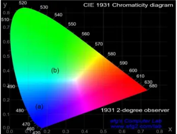
The CIE chromaticity coordinate for this given emission was (0.24, 0.39) (Figure 4, Table 2), close to the white color coordinates. The relative intensities of the blue and the green emissions change from 0.46 in the PL (Figure 3a) to 1 in
Table 1. Optical properties of the PVK:PPFOFPen (1) and PVK:(PFOFPen:[Zn(salophen)(OH2)]) (2) composite
PL EL
PFOFPen [Zn(salophen)(OH2)] PFOFPen [Zn(salophen)(OH2)]
λ0-0 / nm τ/ ns λ/ nm λ0-0 / nm λ/ nm
1 424 0.98 ± 0.04 – 424 –
2 421 0.62 ± 0.04 535 421 515
1: PVK:PPFOFPen; 2: PVK:(PFOFPen:[Zn(salophen)(OH2)]); PL: photoluminescence; EL: electroluminescence; λ0-0: 0-0 band PL or EL wavelength;
λ: PL or EL wavelength.
the EL (Figure 3b). Consequently, the CIE color coordinates
of the EL emission was tuned from (0.16, 0.15)32 in the
ITO/PEDOT:PPS/PVK/PFOFPen/Ca/Al diode towards (0.24, 0.39) in the ITO/PEDOT:PSS/PVK/PFOFPen/
[Zn(salophen)(OH2)] 2.5% mol/mol diode (Table 2).
We propose two possible explanations for the changes of relative intensities in the PL and EL spectra
of the [Zn(salophen)(OH2)]. The first possibility is the
occurrence of the FRET process, involving the PFOFPen
excitons (donor) and the [Zn(salophen)(OH2)] complex
(acceptor) caused by the strong spectral overlap between the PL emission of the PFOFPen and the absorption of
the ZnII complex. As shown, the maximum efficiency of
this process is 37%. However, this is most likely not the only photophysical process playing a role. If FRET were to be the only process taking place, both the EL and PL intensities should be the same. The second process that might explain the differences between intensities in the EL and PL emissions is the charge transport. Charges are probably injected from the electrodes into the PVK and/or PFOFPen phase (due to the favorable band energy as well as the fact that the polymer phase is the dominant one in
terms of quantity). However, the ZnII complex acts as a very
efficient charge trap, since charges tend to go from the larger gap component (PFOFPen) towards the lower band gap
component ([Zn(salophen)(OH2)]). This favors the exciton
formation in the foregoing material, increasing its emission
yield.15,32 This proposal was confirmed by comparing the
energy of the frontier orbitals, HOMO and LUMO, as described by the energy diagram (Figure S3). According to the diagram, the HOMO and LUMO energy levels are the following: –5.8 and –2.3 eV (band gap of 3.5 eV) for the
PVK;39,40 –5.96 and –2.54 eV (band gap of 3.42 eV) for the
PFOFPen;26 and –5.59 and –2.71 eV (band gap of 2.88 eV)
for the [Zn(salophen)(OH2)].31 Thus, there is a possibility
of charge injection from PVK to PFOFPen and from this to the coordination compound in a cascade mechanism. Thus,
exciton formation in the [Zn(salophen)(OH2)] is favored by
both the FRET from the polyfluorene chains and the cascade mechanism by the charge injection process.
The electrical and optical properties of these PLEDs were also determined (Figure 5) in terms of the density
current vs. voltage (a), luminance vs. voltage (b),
current efficiency vs. voltage (c) and current efficiency
vs. luminance (d) curves. The ITO/PEDOT:PPS/PVK/
PFOFPen/Ca/Al diode showed a turn-on voltage (Von)
of 3.0 V, current density of 0.32 A cm-2, luminance of
393 cd m-2 and current efficiency of 139 mcd A-1 (recorded
at 5 V), whereas the electrical properties of the diode
ITO/PEDOT:PPS/PVK/PFOFPen:[Zn(salophen(OH2)]/
Ca/Al showed a small increase of the Von to 3.75 V, an
increase of the current density to 0.74 A cm-2, a decrease
of the luminance to 334 cd m-2 and a current efficiency
of 34 mcd A-1 (both recorded at 7.25 V). Thus, in terms
of performance, the diode with ZnII complex has smaller
luminance/current efficiency. On the other hand, though, it outputs a broader EL spectrum, covering most of the visible spectrum range with a similar brightness (Table 2).
Conclusions
This work showed that polymers and coordination compounds are simple tools with which diodes can be prepared using a unique solution-based deposition. This preparation process may be particularly useful for coordination compounds that are not necessarily highly efficient PL emitters. In the particular case of the
[Zn(salophen)(OH2)] compound, the solid state emission
quantum yield is very low and the EL of its light-emitting
diode (ITO/PEDOT:PSS/PVK/[Zn(salophen)(OH2)]/Ca/Al)
is very inefficient. Nevertheless, when that molecule is incorporated as a guest in a conjugated polymer, the diode performance could be improved with a whitish output emission color. The enormous availability of weak fluorescence coordination compounds opens up a great possibility to explore them as key non-expensive materials to achieve tenable emission on organic light-emitting diodes.
Supplementary Information
Supplementary data are available free of charge at http://jbcs.sbq.org.br as PDF file.
Table 2. Some electrical properties of the diodes: (a) ITO/PEDOT:PPS/PVK/PFOFPen/Ca/Al and (b) ITO/PEDOT:PPS/PVK/PFOFPen:[Zn(salophen(OH2)]/
Ca/Al
Diode λEL / nm Von / V Lmax / (cd m-2) J / (A cm-2) ηmax / (mcd A-1) CIE 1931 (x, y)
a 424 3.0 393 0.09 139 0.16, 0.15
b 424 and 515 3.8 334 0.74 34 0.24, 0.39
a: ITO/PEDOT:PPS/PVK/PFOFPen/Ca/Al; b: ITO/PEDOT:PPS/PVK/PFOFPen:[Zn(salophen(OH2)]/Ca/Al; λEL: electroluminescence wavelength;
Acknowledgments
The authors acknowledge FAPESP (2013/16245-2), CNPq (470529/2012-1), National Institute of Organic Electronics (INEO) (MCT/CNPq/FAPESP) and UNICAMP/FAEPEX for financial support and fellowships.
References
1. Tang, C.; Liu, X. D.; Liu, F.; Wang, X. L.; Xu, H.; Huang, W.;
Macromol. Chem. Phys.2013, 214, 314.
2. Gather, M. C.; Köhnen, A.; Meerholz, K.; Adv. Mater.2011,
23, 233.
3. Sessolo, M.; Tordera, D.; Bolink, H. J.; ACS Appl. Mater. Interfaces2013, 5, 630.
4. Amin, G.; Zaman, S.; Zainelabdin, A.; Nur, O.; Willander, M.;
Phys. Status Solidi RRL2011, 5, 71.
5. Mukherjee, S.; Thilagar, P.; Dyes Pigm.2014, 110, 2.
6. Zhu, M.; Zou, J.; Hu, S.; Li, C.; Yang, C.; Wu, H.; Qin, J.; Cao, Y.; J. Mater. Chem.2012, 22, 361.
7. Yoo, D. Y.; Tu, N. D. K.; Lee, S. J.; Lee, E.; Jeon, S. R.; Hwang,
S.; Lim, H. S.; Kim, J. K.; Ju, B. K.; Kim, H.; Lim, J. A.; ACS Nano2014, 8, 4248.
8. Chen, Y.; Xia, Y.; Smith, G. M.; Sun, H.; Yang, D.; Ma, D.; Li, Y.; Huang, W.; Carroll, D. L.; Adv. Funct. Mater.2014, 24,
2677.
9. Wang, S.; Coord. Chem. Rev.2001, 215, 79.
10. Liu, L.; Chen, F.; Xu, B.; Dong, Y.; Zhao, Z.; Tian, W.; Ping, L.;
Synth. Met.2010, 160, 1968.
11. Yu, J.; Wang, Y.; Liu, Y.; Deng, X.; Tan, H.; Zhang, Z.; Zhu, M.; Zhu, W.; J. Organomet. Chem.2014, 761, 51.
12. Dai, X.; Zhang, Z.; Jin, Y.; Niu, Y.; Cao, H.; Liang, X.; Chen, L.; Wang, J.; Peng, X.; Nature2014, 515, 96.
13. García-López, M. C.; Muñoz-Flores, B. M.; Jiménez-Pérez, V. M.; Moggio, I.; Arias, E.; Chan-Navarro, R.; Santillan, R.;
Dyes Pigm.2014, 106, 188.
14. Stevens, A. L.; Kaeser, A.; Schenning, A. P. H. J.; Herz, L. M.;
ACS Nano2012, 6, 4777.
15. De Deus, J. F.; Faria, G. C.; Iamazaki, E. T.; Faria, R. M.; Atvars, T. D. Z.; Akcelrud, L.; Org. Electron.2011, 12, 1493. 16. Huebner, C. F.; Foulger, S. H.; Langmuir2010, 26, 2945.
17. Turchetti, D. A.; Rodrigues, P. C.; Berlim, L. S.; Zanlorenzi, C.;
0 1 2 3 4 5 6 7 8 9
0.0 0.2 0.4 0.6 0.8 1.0 (a) Current densit y / ( A cm -2 )
Voltage / V
PVK/PFOFPen
PVK/PFOFPen:[Zn(salophen)(OH 2)]
0 1 2 3 4 5 6 7 8 9
0 50 100 150 200 250 300 350 400 450
Voltage / V
PVK/PFOFPen
PVK/PFOFPen:[Zn(salophen)(OH2)]
B ri g h tn e s s / (cd m -2 ) (b)
0 1 2 3 4 5 6 7 8 9
0 20 40 60 80 100 120 140 Current efficienc y / (mcd A -1 ) PVK/PFOFPen
PVK/PFOFPen:[Zn(salophen)(OH2)]
Voltage / V
(c)
0 50 100 150 200 250 300 350 400
0 20 40 60 80 100 120 140
Brightness / (cd m-2)
PVK/PFOFPen
PVK/PFOFPen:[Zn(salophen)(OH2)]
Current efficienc y / (mc d A -1 ) (d)
Figure 5. (a) Current density vs. voltage; (b) brightness vs. voltage; (c) current efficiency vs. voltage; and (d) current efficiency vs. brightness curves of the diodes ITO/PEDOT:PSS/PVK/PFOFPen/Ca/Al () and ITO/PEDOT:PSS/PVK/PFOFPen:[Zn(salophen)(OH2)]/Ca/Al ().
0 1 2 3 4 5 6 7 8 9
0.0 0.2 0.4 0.6 0.8 1.0 (a) Current densit y / ( A cm -2 )
Voltage / V
PVK/PFOFPen
PVK/PFOFPen:[Zn(salophen)(OH
2)]
0 1 2 3 4 5 6 7 8 9
0 50 100 150 200 250 300 350 400 450
Voltage / V
PVK/PFOFPen
PVK/PFOFPen:[Zn(salophen)(OH2)]
B ri g h tn e s s / (cd m -2 ) (b)
0 1 2 3 4 5 6 7 8 9
0 20 40 60 80 100 120 140 Current efficienc y / (mcd A -1 ) PVK/PFOFPen
PVK/PFOFPen:[Zn(salophen)(OH2)]
Voltage / V
(c)
0 50 100 150 200 250 300 350 400 0 20 40 60 80 100 120 140
Brightness / (cd m-2)
PVK/PFOFPen
PVK/PFOFPen:[Zn(salophen)(OH2)]
Current efficienc y / (mc d A -1 ) (d)
Faria, G. C.; Atvars, T. D. Z.; Schreiner, W. H.; Akcelrud, L. C.;
Synth. Met.2012, 162, 35.
18. Xu, X.; Liao, Y.; Yu, G.; You, H.; Di, C.; Su, Z.; Ma, D.; Wang, Q.; Li, S.; Wang, S.; Ye, J.; Liu, Y.; Chem. Mater.2007,
19, 1740.
19. Wang, R.; Deng, L.; Fu, M.; Cheng, J.; Li, J.; J. Mater. Chem.
2012, 22, 23454.
20. Wang, S.; Zhang, B.; Hou, Y.; Du, C.; Wu, Y.; J. Mater. Chem. C
2013, 1, 406.
21. Arias, A. C.; MacKenzie, J. D.; McCulloch, I.; Rivnay, J.; Salleo, A.; Chem. Rev.2010, 110, 3.
22. Nicolai, H. T.; Hof, A.; Blom, P. W. M.; Adv. Funct. Mater.
2012, 22, 2040.
23. De Deus, J. F.; Faria, G. C.; Faria, R. M.; Iamazaki, E. T.; Atvars, T. D. Z.; Cirpan, A.; Akcelrud, L.; J. Photochem. Photobiol., A
2013, 253, 45.
24. Reineke, S.; Thomschke, M.; Lüssem, B.; Leo, K.; Rev. Mod. Phys.2013, 85, 1245.
25. Joo, C. W.; Jeon, S. O.; Yook, K. S.; Lee, J. Y.; J. Phys. D: Appl. Phys.2009, 42, 105115.
26. Quites, F. J.; Faria, G. C.; Atvars, T. D. Z.; Mater. Lett.2014,
130, 65.
27. Farinola, G. M.; Ragni, R.; Chem. Soc. Rev.2011, 40, 3467. 28. Dodabalapur, A.; Solid State Commun.1997, 102, 259.
29. Reineke, S.; Baldo, M. A.; Phys. Status Solidi2012, 209, 2341. 30. Paul, D. R.; Barlow, J. W.; Polymer 1984, 25, 487.
31. Barboza, C. A.; Germino, J. C.; Santana, A. M.; Quites, F. J.; Vazquez, P. A. M.; Atvars, T. D. Z.; J. Phys. Chem. C2015,
119, 6152.
32. Quites, F. J.; Faria, G. C.; Germino, J. C.; Atvars, T. D. Z.;
J. Phys. Chem. A2014, 118, 10380.
33. Quites, F. J.; Domingues, R. A.; Ferbonink, G. F.; Nome, R. A.; Atvars, T. D. Z.; Eur. Polym. J.2013, 49, 693.
34. Quites, F. J.; Germino, J. C.; Atvars, T. D. Z.; Colloids Surf., A
2014, 459, 194.
35. Vladimirova, K. G.; Freidzon, A. Y.; Kotova, O. V.; Vaschenko, A. A.; Lepnev, L. S.; Bagatur’yants, A. A.; Vitukhnovskiy, A. G.; Stepanov, N. F.; Alfimov, M. V.; Inorg. Chem.2009, 48, 11123.
36. Förster, Th.; Discuss. Faraday Soc.1959, 27, 7. 37. Braslavsky, S. E.; Pure Appl. Chem.2007, 79, 293.
38. Lakowicz, J. R.; Principles of Fluorescence Spectroscopy, 3rd ed.; Springer Science+Business Media, LLC: New York, 2006.
39. Solomeshch, O.; Yu, Y. J.; Medvedev, V.; Razin, A.; Blumer-Ganon, B.; Eichen, Y.; Jin, J. I.; Tessler, N.; Synth. Met.2007,
157, 841.
40. Jun, W. G.; Cho, M. J.; Choi, D. H.; J. Korean Phys. Soc.2005,
47, 620.
Submitted: June 29, 2015
Published online: September 18, 2015
![Figure 1. Chemical structures of (a) poly[(9,9-dioctylfluorenyl-2,7-diyl)-alt-co-(9,9-di-{5’-pentanyl}-fluorenyl-2,7-diyl)] (PFOFPen); (b) poly(9- poly(9-vinylcarbazole) (PVK) and (c) aquo[N,N’-bis(salicylidene)-o-phenylenediamine]zinc(II) ([Zn(salophen)(O](https://thumb-eu.123doks.com/thumbv2/123dok_br/19000315.463532/2.892.113.760.839.1068/chemical-structures-dioctylfluorenyl-pentanyl-fluorenyl-vinylcarbazole-salicylidene-phenylenediamine.webp)

![Figure 3a also presents the PL spectra of PVK/PFOFPen:[Zn(salophen)(OH 2 )] composite on ITO substrate](https://thumb-eu.123doks.com/thumbv2/123dok_br/19000315.463532/4.892.452.796.109.631/figure-also-presents-spectra-pfofpen-salophen-composite-substrate.webp)
![Table 2. Some electrical properties of the diodes: (a) ITO/PEDOT:PPS/PVK/PFOFPen/Ca/Al and (b) ITO/PEDOT:PPS/PVK/PFOFPen:[Zn(salophen(OH 2 )]/](https://thumb-eu.123doks.com/thumbv2/123dok_br/19000315.463532/6.892.71.798.165.228/table-electrical-properties-diodes-pedot-pfofpen-pfofpen-salophen.webp)
